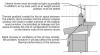
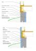
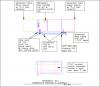
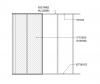
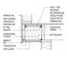
Preview Image Condensation in storm windows can be prevented by air sealing around the storm window and allowing some ventilation to the outside from the original window
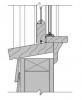
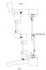
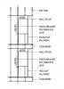
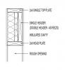
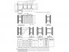
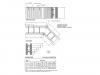
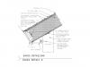
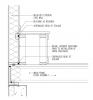
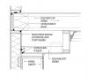
Preview Image Assemblysill details for a site built, refurbished window that includes a permanent interior storm window. CAD File DWG PDF Version PDF
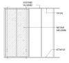
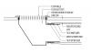
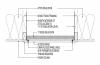
Preview Image Permanently attached openable interior storm window viewed from the side; outside of home is to right, interior storm pane is on right.
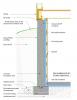
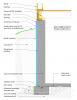
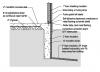
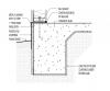
Preview Image Foundation wall interior polyisocyanurate, foil-faced, exposed CAD File DWG PDF Version PDF
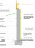
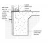
Preview Image Foundation wall interior rigid insulation with furring strips CAD File DWG PDF Version PDF
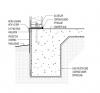
Preview Image Polyethylene sheet under the slab extends down and under the foundation wall CAD File DWG PDF Version PDF
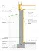
Preview Image Spray foam on concrete foundation wall with framed interior wall CAD File DWG PDF Version PDF
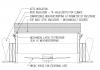
Preview Image Front view of vertical air handler condensate disposal and controls CAD File DWG PDF Version PDF
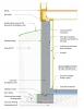
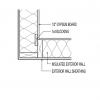
Preview Image Foundation wall interior rigid insulation with framed wall CAD File DWG PDF Version PDF
Preview Image Front view of horizontal air handler showing condensate drain pans and drain lines CAD File DWG PDF Version PDF
Preview Image Front view of horizontal air handler showing condensate drain pans, pipes, and controls CAD File DWG PDF Version PDF
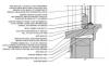
Preview Image CAD image for roof pipe penetration water and air sealing details CAD File DWG PDF Version PDF
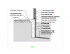
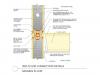
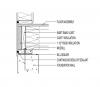
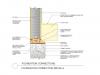
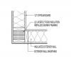
Preview Image Foundation Wall Exterior board insulation without above-grade wall insulation CAD File DWG PDF Version PDF
Preview Image 2x10 Rafter - Insulation Above Roof Deck and In Rafter Cavity CAD CAD File DWG PDF Version PDF
Preview Image 2x10 Rafter - Insulation Below Roof Deck In Rafter Cavity CAD CAD File DWG PDF Version PDF
Preview Image 2x12 Rafter - Insulation Above Roof Deck and In Rafter Cavity CAD CAD File DWG PDF Version PDF
Preview Image 2x12 Rafter - Insulation Below Roof Deck In Rafter Cavity CAD CAD File DWG PDF Version PDF
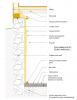
Preview Image Polyethylene sheeting covers the aggregate and extends down and under the footing to provide a capillary break between the ground and the slab and monolithic footing CAD File DWG PDF Version PDF
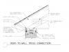
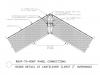
Preview Image Connection of two SIP roof panels with beveled edges at roof ridge CAD File DWG PDF Version PDF
Preview Image Connection of a SIP roof panel to a beveled SIP wall panel CAD File DWG PDF Version PDF
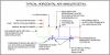
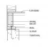
Preview Image Front view of horizontal air handler showing outdoor air intake, dampers, supply and return, emergency drain pan, and drain overflow safety cut off switch CAD File DWG PDF Version PDF
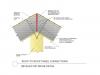
Preview Image Connection of a SIP roof panel to a SIP roof panel with a foam ridge cap CAD File DWG PDF Version PDF
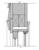
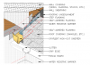
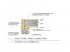
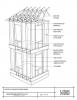
Preview Image Connection of the first floor and second floor wall panels with a hanging floor CAD File DWG PDF Version PDF
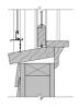
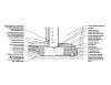
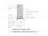
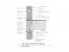
Preview Image Connection of foundation wall to rim joist to SIP wall panel CAD File DWG PDF Version PDF
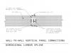
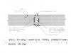
Preview Image Connection of SIP wall panels with dimensional lumber splines CAD File DWG PDF Version PDF
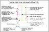
Preview Image Front view of horizontal air handler showing outdoor air intake, dampers, supply and return, and condensate drain pans, drain pipe and trap, and drain overflow safety cut off switch CAD File DWG PDF Version PDF
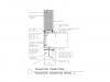
Preview Image Connection of a concrete foundation wall to SIP wall panel with a sill plate and floor joist CAD File DWG PDF Version PDF
Preview Image Connection of a SIP roof panel to a SIP wall panel with a wedge infill piece CAD File DWG PDF Version PDF
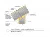
Preview Image Connection of two SIP roof panels with beveled edges at roof ridge with support for roof cantilever overhang CAD File DWG PDF Version PDF
Preview Image Connection of first and second floor SIP wall panels with a floor joist in between CAD File DWG PDF Version PDF
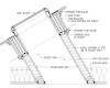
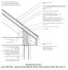
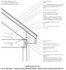
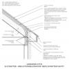
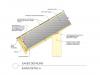
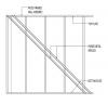
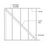
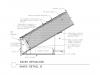
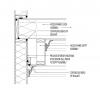
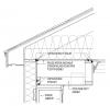
Preview Image SIP roof panel detailing at the eaves with a vertical fascia and soffit board CAD File DWG PDF Version PDF
Preview Image SIP roof panel detailing at the eaves with a framed overhang, a vertical fascia and soffit board CAD File DWG PDF Version PDF
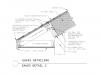
Preview Image SIP roof panel detailing at the eaves with a short overhang, a vertical fascia and soffit board CAD File DWG PDF Version PDF
Preview Image SIP roof panel detailing at the eaves with an angled fascia and soffit board CAD File DWG PDF Version PDF
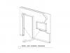
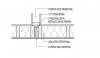
Preview Image Interior intersecting wall with 2 studs and rigid insulation CAD File DWG PDF Version PDF
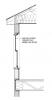
Preview Image Conceptual line of continuous air barrier - upper wall section CAD File DWG PDF Version PDF
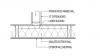
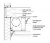
Preview Image Air sealing at interior wall between conditioned space and unconditioned attic CAD File DWG PDF Version PDF
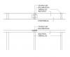
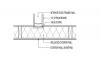
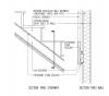
Preview Image Insulated cantilever floor - cavity insulation with 1 inch rigid insulation closure CAD File DWG PDF Version PDF