

Scope
Use the interstitial floor space between the conditioned levels of a home to provide space for HVAC ducts within the thermal envelope of the home
- Use the interstitial floor
- If there is sufficient space in the floor cavities to house the ducts
- If the ducts can be routed through the floor cavities, usually through open-web floor joists.
- Insulate and air seal the rim joists and integrate the insulation and air sealing boundaries with the home’s thermal envelope.
- During design, plan the path of the duct system to be housed in the floor cavity including truss type (e.g. open web) and modifications.
- During design, work with both the HVAC contractor and the truss designer to ensure the duct sizes will fit, with adequate room for attachment, in the truss spacing, openings and/or webs.
- Develop the thermal and air barrier detailing needed to separate the floor cavity from the outside and all adjacent unconditioned spaces.
- During construction, after the house is dried in, mark the path of the duct system.
- Mark the edges (rim joists) of the conditioned floor cavity, including exterior walls, and any attic knee walls, garage walls, and stair well walls.
- Identify areas where the duct crosses the edge of the conditioned floor cavity. Resolve conflicts.
- Install additional framing needed to support the thermal and air barriers at the edge of the floor cavity. Identify and seal framing between vertical chases and the floor cavity. Add air barrier material as needed.
- Ensure that a durable air barrier material covers the entire perimeter of the floor cavity and that this air barrier integrates with the whole house air barrier above and below. Seal all penetrations, edges, and joints.
- At mechanical rough-in, install the ducts in the floor cavity following guidelines for quality installation.
- Test the ducts for air tightness and repair air leaks.
- Seal all penetrations between the floor cavity and adjacent unconditioned spaces and building cavities.
- Install a durable and continuous layer of insulation along the floor cavity perimeter that aligns with the insulation above and below the floor cavity.
See the Compliance Tab for links to related codes and standards and voluntary federal energy-efficiency program requirements.
Description
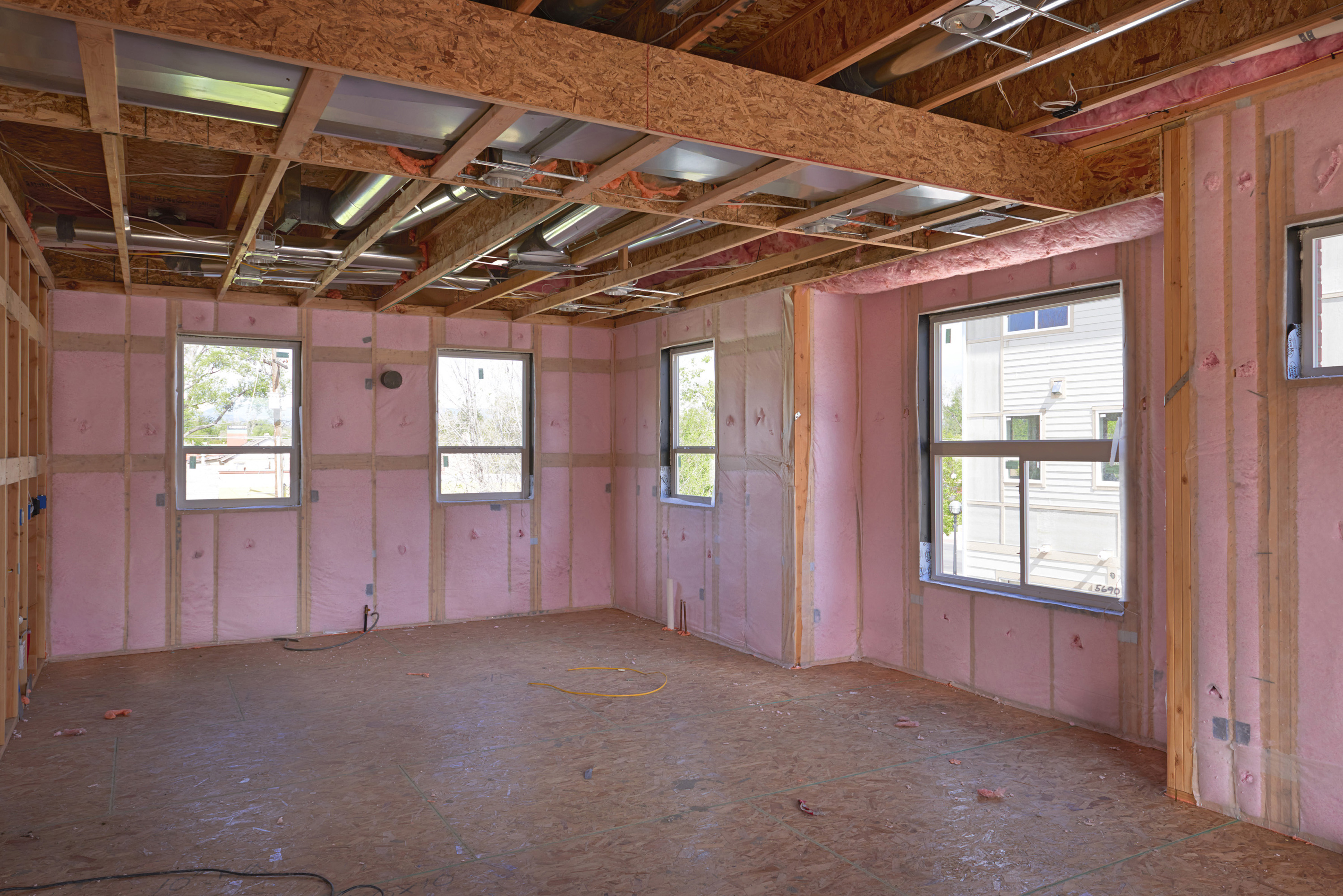
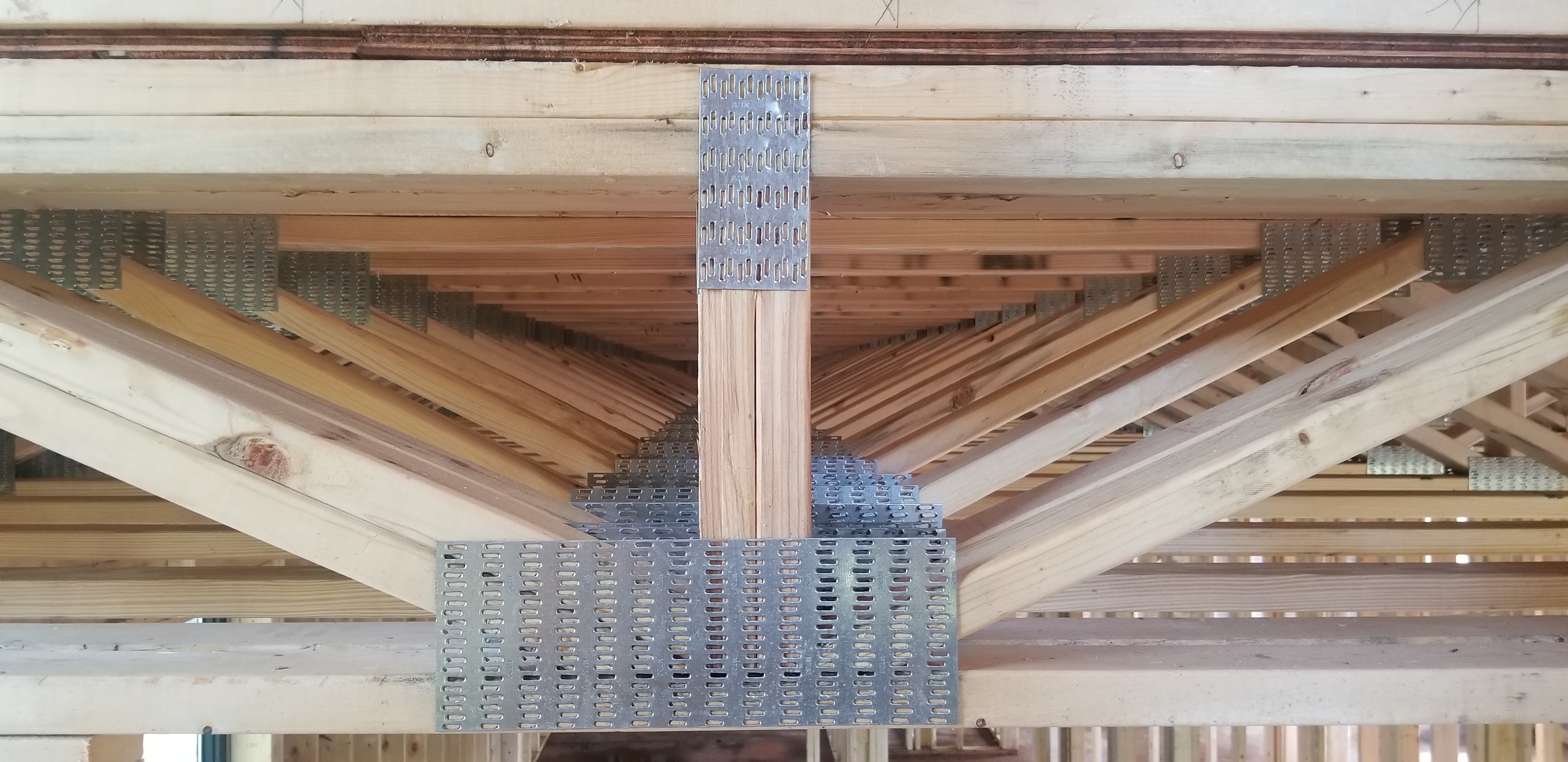
Building cavities, sometimes called interstitial spaces, include framed floor cavities between upstairs and downstairs conditioned rooms. This floor cavity space can be used to house supply and return ducts if there is adequate room to avoid compressing the duct and compromising air flow (in BASC see: “Sufficient Cavity Space for Flex Ducts”) and if there is an adequate unobstructed path for each duct. This is made possible largely by open-web floor joists that allow duct runs to go in perpendicular directions. This can be considered “interior ductwork” or “ducts in conditioned space” when the floor cavity is separated from adjacent unconditioned and outdoor spaces by thermal and air flow barriers that integrate with the other elements of the whole house thermal and air barriers.
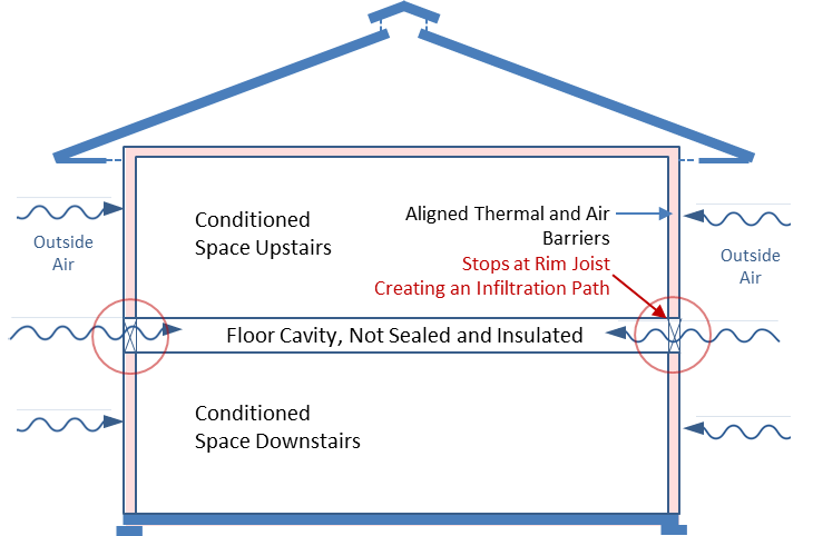
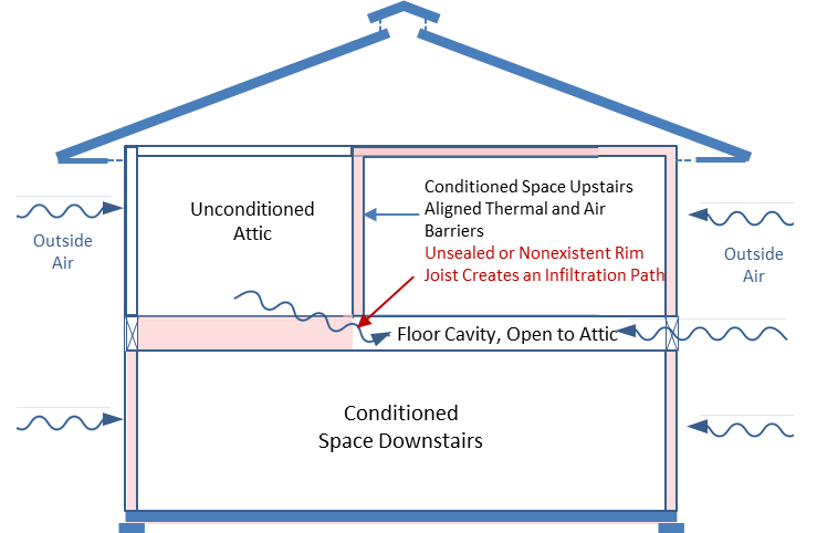
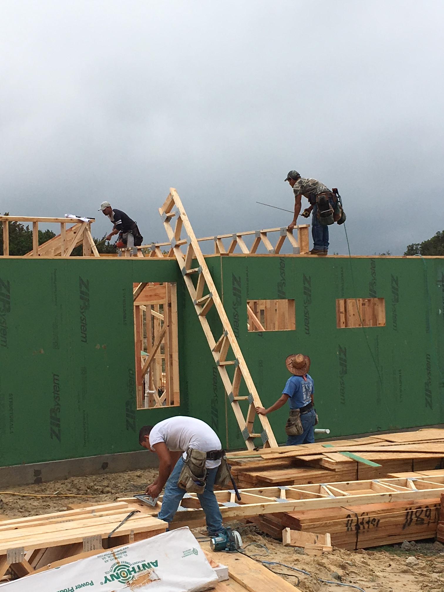
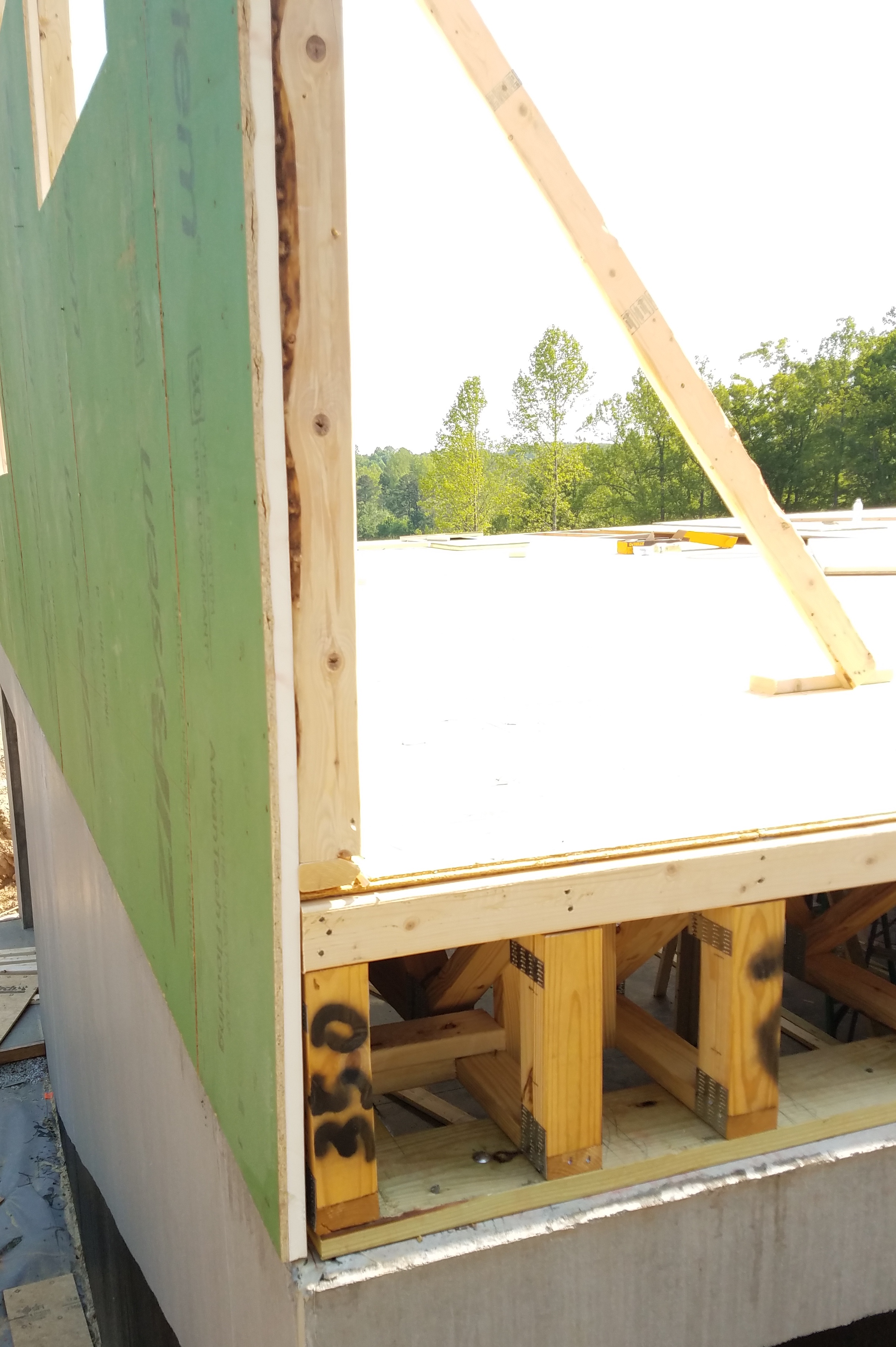
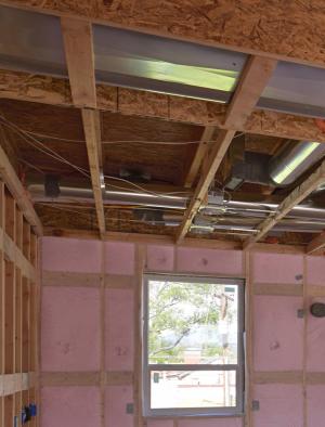
While floor cavities normally fall within the exterior finishes of a house, they are not technically considered conditioned space because there is no intentional air exchange with the conditioned spaces above and below or the conditioned air distribution system. Additionally, they may be connected to the outdoors (Figure 1) or adjacent unconditioned spaces (Figure 2) such that outside or unconditioned air can move into the floor cavity.
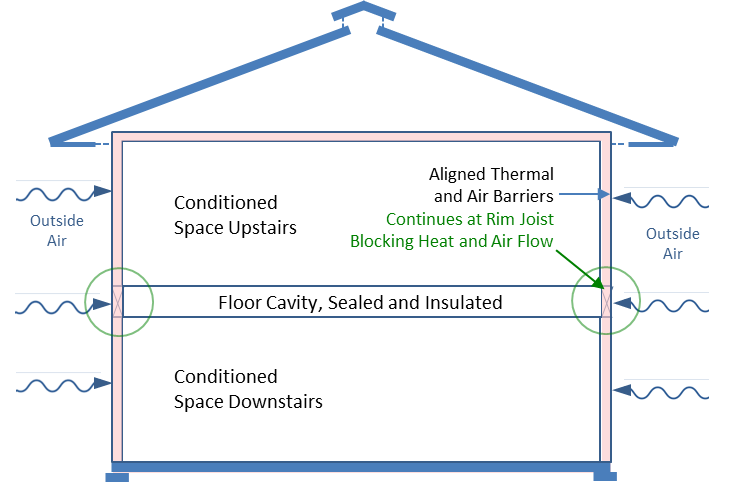
They can be considered quasi-conditioned spaces if they have been sufficiently separated from adjoining exterior and unconditioned spaces by continuous thermal and air flow barriers that are integrated with the rest of the whole house thermal and air flow barriers (in BASC see: “Continuous Air Barrier in Exterior Walls”)
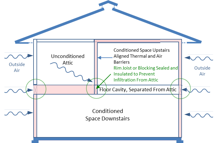
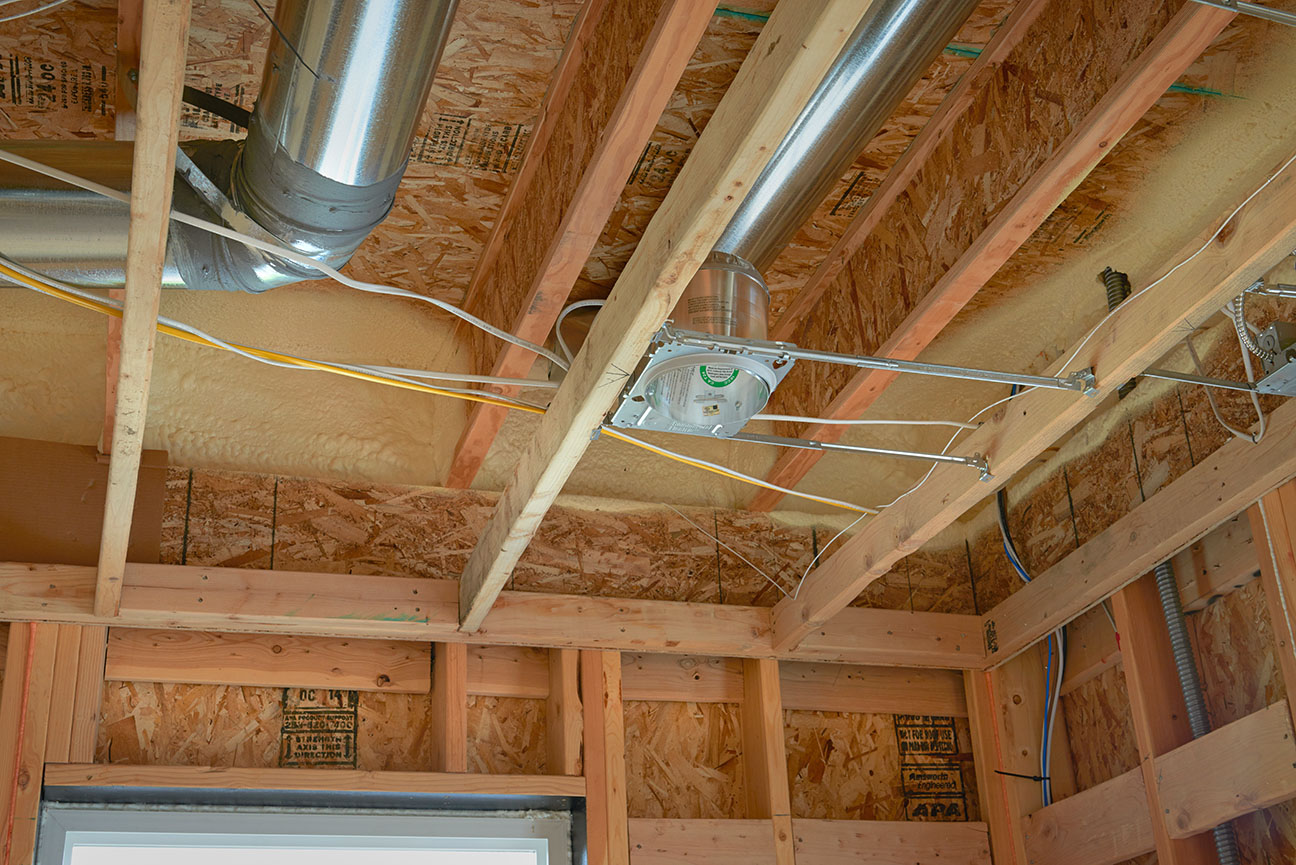
Separating the floor cavity from adjacent outside and unconditioned spaces requires sealing all penetrations in the rim joists that form the edges of the floor cavity and insulating the rim joists in a manner consistent with walls above and below or adjacent attic insulation (Figure 3). With this heat transfer and infiltration boundary in place, the floor cavity temperature will be more like the conditioned spaces above and below rather than like the adjacent unconditioned or exterior spaces. Ducts located in such insulated and air-sealed frame floor cavities can be classified as “interior ducts” or “ducts in conditioned space” for purposes of compliance with energy-efficiency programs like DOE’s Zero Energy Ready Home program. Program requirements may specify insulation location and R-value.
Source
Source
Source
In addition to separating the floor cavity from the outside, it must be separated from any adjacent unconditioned space such as a vented attic (Figure 4) or crawl space, garage, vertical chase connected to a vented attic or crawl space, or wall enclosing a stair well (in BASC see: “Wind Washing,” and “Garage Rim/Band Joist adjoining Conditioned Space,”). It may be necessary to add framing to support thermal and air flow barriers. Observe local codes for fire rating requirements for sealants, materials, and assemblies.
Source
When the floor cavity extends over exterior space, follow guidelines for air sealing and insulating the cantilevered floors (in BASC see: “Cantilevered Floor”).
When the floor cavity extends into a vented attic, follow guidelines for sealing and insulating floor joist cavities under knee walls (in BASC see: “Attic Knee Walls”)
Generally, a floor cavity is not deep enough to accommodate both a supply duct system and a return duct system if the two systems must cross over each other. If only a portion of the duct system is located in the floor cavity, the remainder of the air distribution system including the air handler must be located in other conditioned spaces for the whole system to be classified “ducts in conditioned space” (See Compliance tab for details on requirement of the DOE Zero Energy Ready Home Program.) This could be in a utility room within the home or in an unvented, insulated crawlspace, an air-sealed, insulated basement, or an unvented, insulated attic. Also see: “Ducts in Conditioned Space” by Building Science Corporation).
Ducts located in floor cavities above a vented crawl space or unconditioned basement are not considered to be in conditioned space because they are not separated from unconditioned space by air and thermal barriers. In this case, see BASC guidance for “Floor above Unconditioned Basement or Vented Crawlspace”.
Note that this guide describes methods for installing ducts within floor cavities. The floor cavities themselves should not be used as supply or return ducts. See the Building America Solution Center (BASC) guide “Building Cavities Not Used as Supply or Return Ducts”) for more information.
How to Install Interior Ducts in Interstitial Floor Framing
Step 1: Using an integrated design process that includes input from the structural designer and mechanical contractor, develop a duct plan and the thermal and air barrier detailing needed to separate the floor cavity from the outside and all adjacent unconditioned spaces.
The duct plan should include the exact location of the floor cavity edge (where the thermal and air barriers will be installed), the location of all registers, junction boxes, plenums, and connections to elements of the air distribution not in the floor cavity. Also define the location of critical floor cavity structural elements and vertical chases passing through the floor cavity.
Consideration must be paid simultaneously to duct design and the structural design of the floor cavity. Duct dimensions and path must mesh with the direction and depth of floor framing members while providing for appropriate location of supply and/or return registers. In general, a straight duct trunk is paired with short, straight branch duct (runouts) to reach individual rooms. Engineered openings provide a path for trunks or branch ducts running perpendicular to the framing members.
Clearly identify the perimeter of the floor cavity to be included within the whole house thermal and air barriers. Decide what materials will be used for the thermal and air barriers and how they will be installed. Incorporate details into wall sections in the construction documents, bid documents for each trade involved, and pre-construction reviews with trade contractors involved prior to implementation.
Step 2: After the house is dried in, mark the exact location of the edge of the floor cavity to be included in the whole house thermal and air barrier with colored tape, marker, etc. Identify the intersections between the floor cavity and the whole house thermal and air barriers which may involve attic knee walls, garage walls, and stair well walls. This should extend around the entire perimeter of the floor cavity including where the floor cavity extends over exterior space (cantilevers) and into vented attics. Identify areas where additional framing is needed to support thermal and air barrier materials. Identify areas, if any, where the rim joist air barrier needs to be integrated with the whole house drainage plane or vapor barrier. These are complex details. This is the time to clarify how the details in the construction documents will be executed at every point along the floor cavity edge and at all penetrations. Resolve conflicts prior to beginning installation of thermal and air barriers.
Step 3: To be done in tandem with Step 2, mark the path of the duct system to ensure it does not cross the edge of the floor cavity. Resolve conflicts.
Step 4: Per construction documents and any resolutions resulting from Steps 2 and 3, install additional framing needed to support the thermal and air barriers at the edge of the floor cavity and at openings in the floor cavity for vertical chases.
Step 5: Working around the entire edge of the floor cavity and all penetrations, install a durable air barrier material that continues or integrates with the whole house air barrier above and below. Seal all penetrations, edges, seams, and joints. In BASC, see “Continuous Air Barrier in Exterior Walls”.
Step 6: At mechanical rough-in, install the ducts in the floor cavity following guidelines for quality installation. Never modify a structural member to accommodate a duct. Resolve conflicts by adjusting the duct design. Conduct preliminary duct leakage testing on the ducts. Mark leaks. Work with the mechanical contractor to eliminate leakage while the floor cavity is still open to the space below.
Step 7: Prior to installing insulation, seal all penetrations between the floor cavity and outside space, unconditioned spaces, and building cavities.
Step 8: Install a durable and continuous layer of insulation that aligns with the insulation above and below the floor cavity. In BASC see: “Attic Knee Walls”, “Garage Rim/Band Joist Adjoining Conditioned Space”, and “Continuous Air Barrier in Exterior Walls”.
Ensuring Success
Do not operate portable combustion heaters in the house once air sealing has commenced.
Make every effort to seal all penetrations and sections of the floor cavity edge prior to drywall installation on the ceiling below while the floor cavity is still accessible from below. Upon completion, the floor cavity should be substantially air tight with no part of the cavity interior evident in a visual inspection.
Avoid placing recessed lighting fixtures in the ceiling plane below a floor-mounted duct run. For nearby recessed fixtures, select models that are Insulation Contact and Air Tight (ICAT)-rated to reduce heat transfer to ducts.
Ultimately the vertical duct dimension must be less than the minimum vertical clearance along its path within the floor cavity. Vertical clearance may be affected by horizontal blocking, cross bracing, plumbing, and wiring runs. Plan for a generous vertical allowance to accommodate unforeseen horizontal elements and minor inaccuracies in duct construction.
During design, mock up duct sections and floor framing during design. Small inaccuracies in duct construction are common and can increase vertical duct dimension beyond the allowance in a tightly designed floor cavity. For example, a mock-up can help ensure that the design dimensions of junction boxes allow adequate clearance for installing the flex duct collars.
During Step 2, mock up a portion of the thermal and air barrier installation at the floor cavity edge. Review with each trade contractor involved to ensure responsibilities are mutually understood.
Ideally, all ducts, including those in floor cavities, should be well built, thoroughly sealed, and insulated to ensure conditioned air is delivered to the intended space at the correct temperature (in BASC, see “Sealed and Insulated Flex Ducts”, “Sealed and Insulated Fiber Board Ducts”, and “Sealed and Insulated Metal Ducts”
Rather than waiting until the finish mechanical work is done, conduct a duct leakage test after mechanical rough-in but prior to closing up the floor cavity. All duct air-sealing materials should be thoroughly dry and hardened. Install a temporary air barrier (e.g., card board) wherever a portion of the duct system is missing, such as at the supply and/or return plenums, if the air handler has not been set. Seal the temporary air barrier in place with tape or duct mask so that no air can pass through the opening during testing. If higher-than anticipated air leakage is measured, use the duct testing fan to very slightly pressurize the ducts in the floor cavity. Leakage sites can be detected by feeling for air flow at duct connections or using smoke detection pencils. It is best to have the mechanical contractor on site during this test to make repairs as they are found. If that is not possible, mark the leakage sites on the duct work to reduce confusion during repairs. Do not retest the duct system until all sealants are dry and hardened.
Region
Guide contents are applicable to all climates. See the Compliance Tab for climate-zone-specific requirements for insulation and air sealing.
Training
Right and Wrong Images
Source
Source
Source

Source
Source
Source
Source
Source
Compliance
Retrofit
SCOPE
In existing homes, where the ducts are already located within the floor cavities between conditioned spaces, make any needed or available improvements to the thermal boundary of the floor cavity.
- Test the air tightness of the floor cavity with respect to the outside.
- Air seal all accessible leakage spots in the top, bottom, and sides of the floor cavity, as described in the Description tab.
- Enclose any portions of the HVAC system that are installed in unconditioned space.
- Perform air sealing of any accessible parts of the duct system, for example around duct boots at registers and at the air handler cabinet.
For more information see the U.S. Department of Energy’s Standard Work Specifications’ guidance on ducts.
DESCRIPTION
In most cases, floor cavities are inaccessible in existing homes. Additionally, floor joists in existing homes will typically be made of dimensional lumber, which would not allow installation of branching duct runs. These factors combine to make it nearly impossible to retrofit duct work into an existing floor cavity. Floor cavities that already contain duct work may be equally inaccessible; however, any accessible edge in such floor cavities may be treated as described in the new construction tabs. In this case, the design tasks and on-site layout of the duct system in the Scope tab do not apply to existing homes.
In addition to duct testing, thermal imaging of duct work under normal operating conditions may be useful for locating leaks in both ducts and the floor cavity. Duct repair may be hampered by accessibility issues.
When existing ducts cross the intended edge of the conditioned floor cavity, for example partially extending into an adjacent vented attic, enclose the space around each duct run with thermal and air barriers to extend a portion of the conditioned floor cavity.
While retrofitting ducts into an existing floor cavity is likely unrealistic because of poor access, it is possible and recommended to install thermal and air barriers at any accessible edge of the floor cavity containing duct work. While it may be beneficial, it is not necessary to enclose the entire floor cavity – just the portions of the interstitial floor framing that contains duct work. This is an important distinction that may save time and money during implementation.
Accessible edges are usually found in adjacent unconditioned spaces such as a garages and attics. The primary tasks are the same as in new construction: define the exact location of the intended conditioned floor cavity, design and install thermal and air barriers at the edge and all penetration. In existing homes, blower door and duct leakage testing can be used before and after repair to assess effectiveness.
This topic is addressed in the BASC guide “Wind Washing” guide as it pertains to floor cavities adjacent to vented attics.
How to Create Interior Ducts in Existing Interstitial Floor Framing
Preliminary assessments: Prior to beginning design, conduct the following pre-retrofit assessments to determine existing conditions and develop a plan for ensuring operating conditions of the home remain safe:
Step 1: For design purposes, make an as-built drawing of the existing floor cavity, duct work, vertical elements passing through the floor cavity (e.g. plumbing stacks), adjoining unconditioned or exterior spaces, and any duct leakage issues found through visual inspection or thermal imaging. Focus the integrated design process on locating the intended edge of the conditioned floor cavity, recognizing that only the portion of the floor cavity containing duct work needs to be isolated and that a portion of the edge is likely inaccessible. Proceed with other tasks in the new construction Step 1. Additionally, after developing the thermal and air barrier detailing needed to separate the floor cavity from the outside and all adjacent unconditioned spaces, test the method in a small portion of the floor cavity. Refine the method as needed.
Step 2: See the Description tab, step 2.
Step 3: Disregard new construction guidance. Instead, conduct a whole house (blower door) and duct air tightness testing to serve as a benchmark for gauging success of improvements. Identify and repair duct leakage sites. Thermal imaging conducted while the mechanical system is operating normally may help in identifying areas of high duct leakage. Duct repair may be hampered by accessibility issues; however, leakage at registers and accessible connections can improve overall performance and should be made. If a majority of leakage sites are inaccessible, consider hiring a trained technician to inject a foam sealant that will seal the ducts from the inside. This topic is addressed in “Injected Spray Sealant for Existing HVAC Ducts”.
Repeat tests to assess impact of duct repairs.
Steps 4 and 5: See the Description tab, steps 4 and 5.
Step 6: Disregard new construction guidance. Instead, repeat both whole house and duct testing to assess the impact of sealing the floor cavity. Repeat thermal imaging, if available, to assess impact in specific problem areas. Repeat pressure measurement(s) in the floor cavity during blower door testing to assess improvement in connectivity to conditioned space. Make repairs as needed and repeat testing.
Steps 7 and 8: See the Description tab, steps 7 and 8.
ENSURING SUCCESS
Prior to air sealing the floor cavity edge, review and follow guidelines for maintaining combustion safety if unvented space heaters or atmospherically vented gas furnaces or water heaters are present in the home or in a space adjacent to the targeted floor cavity. In BASC, see “Assess and Correct Combustion Safety” (link to be provided by PNNL), “Measure Guideline: Combustion Safety for Natural Draft Appliances Using Indoor Air” and “Measure Guideline: Combustion Safety for Natural Draft Appliances Through Appliance Zone Isolation”.
Air seal adjacent exterior walls, walls separating porch attics from the home, floor joist cavities under attic knee walls and rim joist at cantilever floors. Use blower door testing in combination with visual inspection and infrared thermography to identify areas of infiltration and to verify repairs.
When accessible, panned floor joist cavities functioning as air distribution pathways should be abandoned and replaced with properly sized, well-built and sealed ducts appropriately supported. If the duct fits in a joist bay, an air barrier can be attached to the bottom of the joists and sealed following steps in the Description tab.
Review procedures and details related to floor cavities adjacent to vented attic spaces in the BASC guide “Wind Washing”
COMPLIANCE (Codes, Standards, and Program Criteria)
Consult local building officials regarding relevance of codes to existing home modifications.
Home Performance with Energy Star
Home Performance with Energy Star, the home improvement arm of Energy Star, is not a national program. It is administered through a limited number of sponsors that create and execute a local program. Requirements for certification vary among local programs. (See Full List of Home Performance with ENERGY STAR Programs).
ENERGY STAR Single-Family New Homes
Homes undergoing gut rehab can be certified under the Energy Star for Homes, New Construction Standard if they meet all the requirements including those called out on the Compliance tab for new construction.
See Compliance tab.
More Info
References and Resources
*For non-dated media, such as websites, the date listed is the date accessed.
Contributors to this Guide
The following authors and organizations contributed to the content in this Guide.
Sales
HVAC Ducts in Interstitial Floor Framing
Technical Description
Comfort systems work much better when they are located in the conditioned space of the home rather than in an unconditioned attic or crawl space. One option is framing-integrated comfort delivery which locates the heating and cooling ducts between floors. Builders are using more engineered framing products rather than dimensional lumber. Engineered products like open-web floor joists may provide adequate height and size openings for heating and cooling ducts, especially in high-performance homes with small space conditioning loads.
Questions? Comments? Contact our webmaster.