

Scope
Air-seal and insulate flex ducts.
- Design a compact duct layout with short, straight runs and minimal bends. Design the home to include ducts within conditioned space if possible. (The DOE Zero Energy Ready Home program requires that heating/cooling system supply ducts be installed within the conditioned space of the home.)
- Install flex duct that is pre-insulated with a layer of fiberglass blanket insulation covered with a foil or plastic vapor barrier.
- Use insulated duct for all supply and return ducts located in unconditioned space. Meet code or program minimum R-value requirements. See the Compliance tab for R-value minimum requirements specified in the IRC, IECC, DOE Zero Energy Ready Home program, and ENERGY STAR criteria.
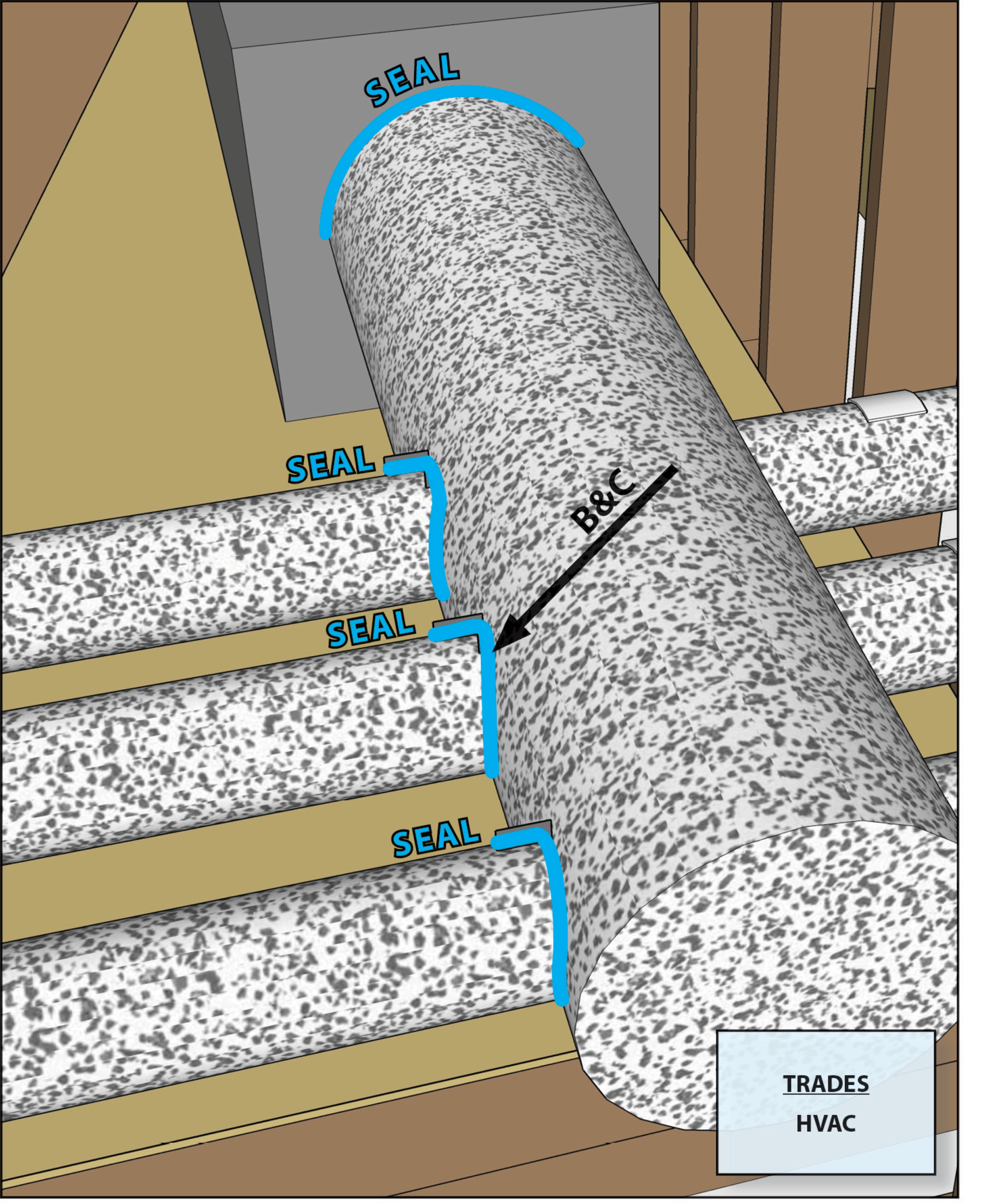
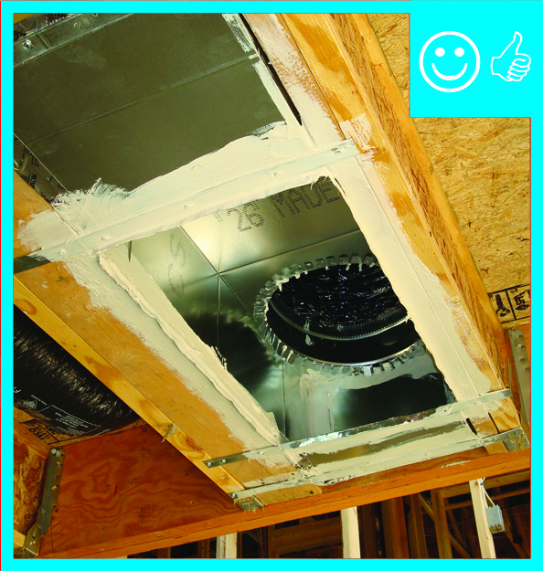
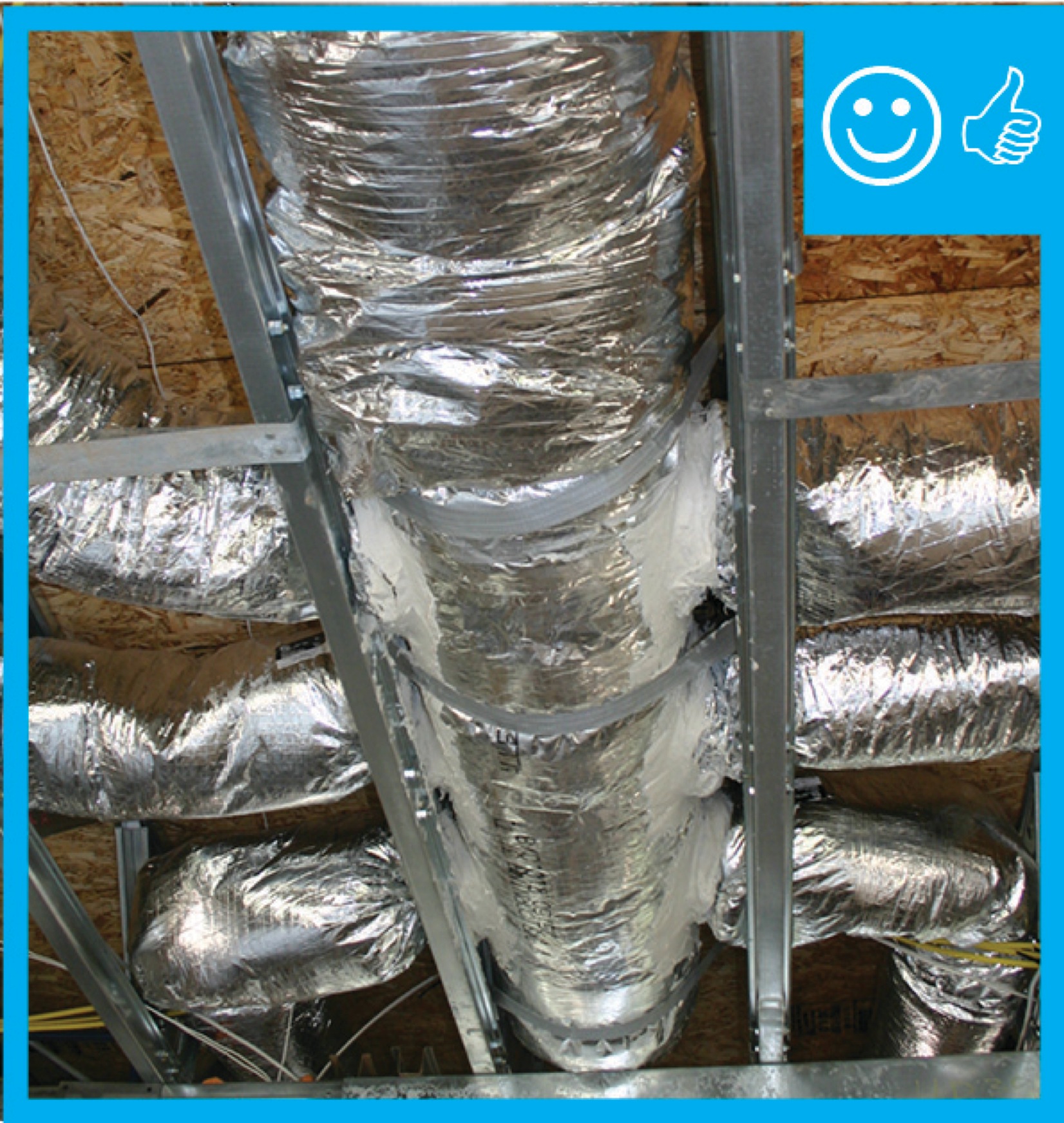
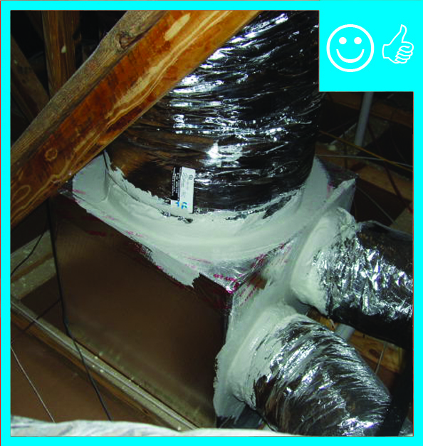
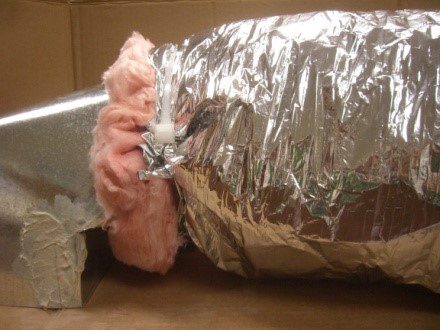
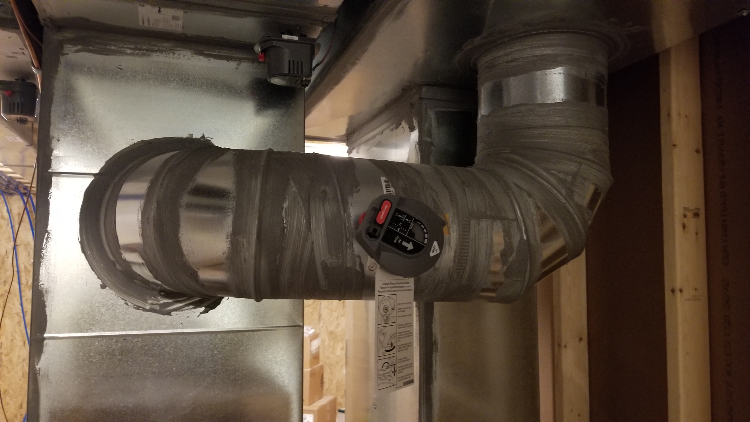
- Connect flex duct to boots, trunk lines, and return boxes by pulling flex duct over the raised bead on the metal connection collar and fastening with a nylon draw band pulled tight with a tensioning tool. Seal the duct-collar junctions with mastic.
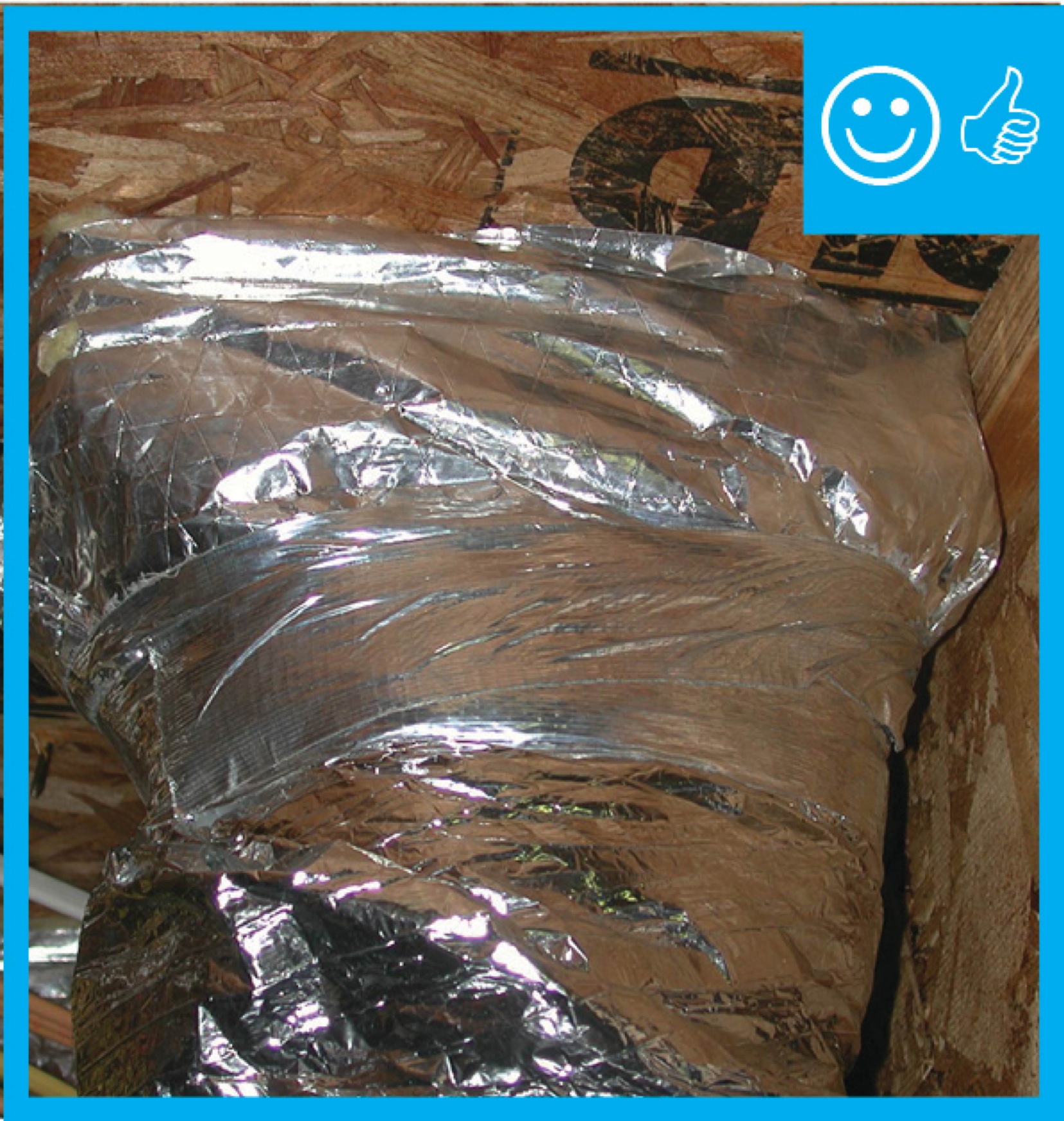
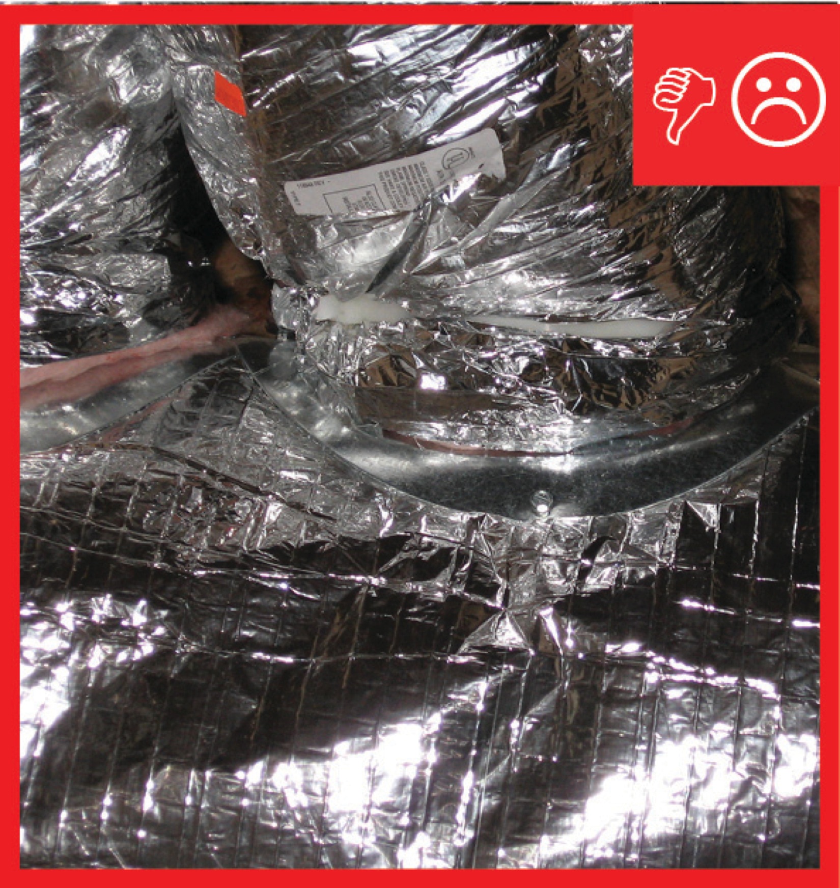
- Pull insulation wrapped in vapor barrier over the connections and seal seams with both UL-181-approved tape and mastic. Do not compress the insulation.
- Ensure that all flex duct connections are air sealed for the following, regardless of whether they are located in conditioned or unconditioned space:
- supply ducts (connections to boots, trunk ducts, other ducts, i.e., duct splicing);
- return ducts (connections to return box);
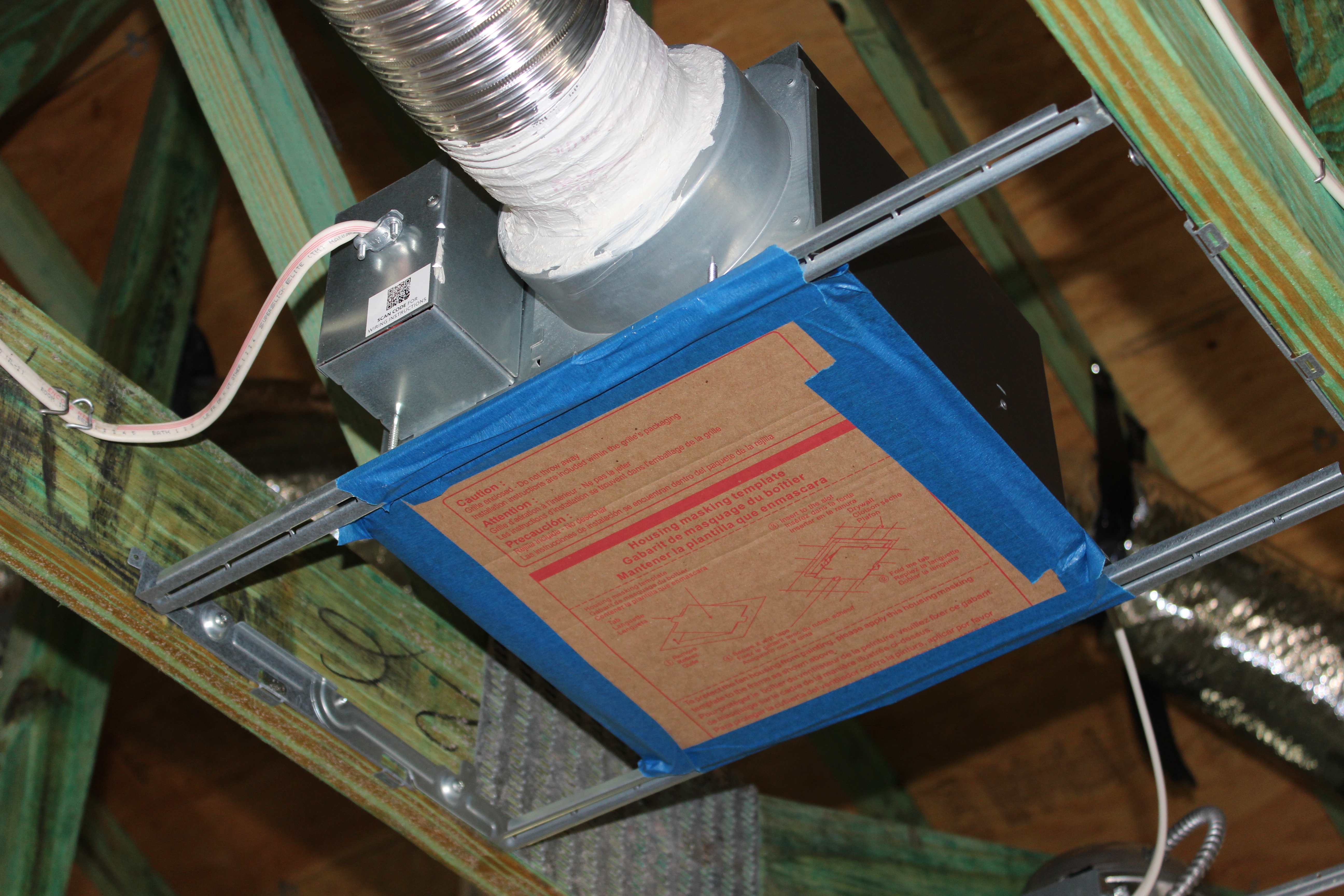
- ventilation ducting (connections to exhaust fans, for ERV/HRV dedicated ducts)
- pressure balancing (connections for jump ducts, dedicated returns).
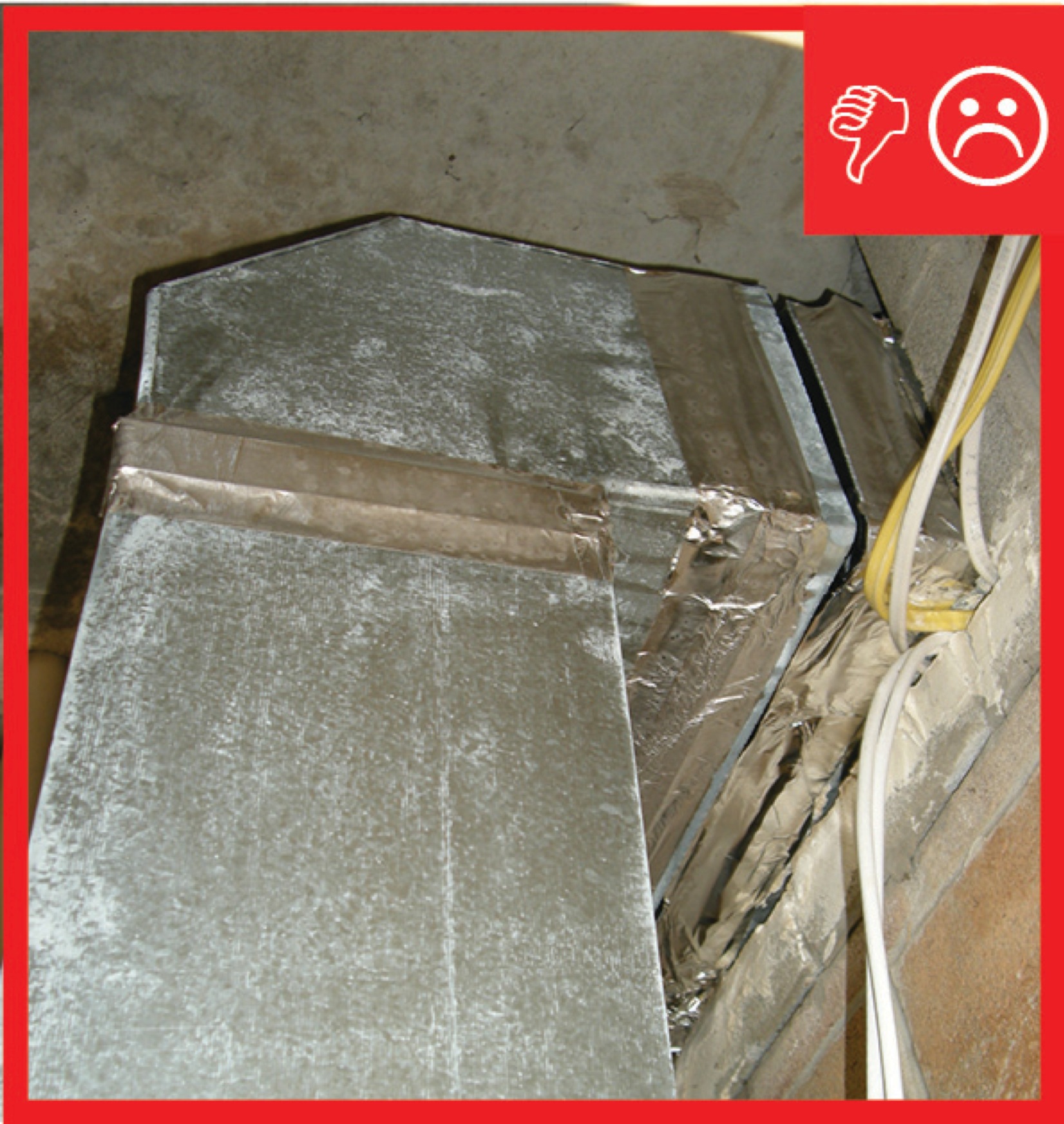
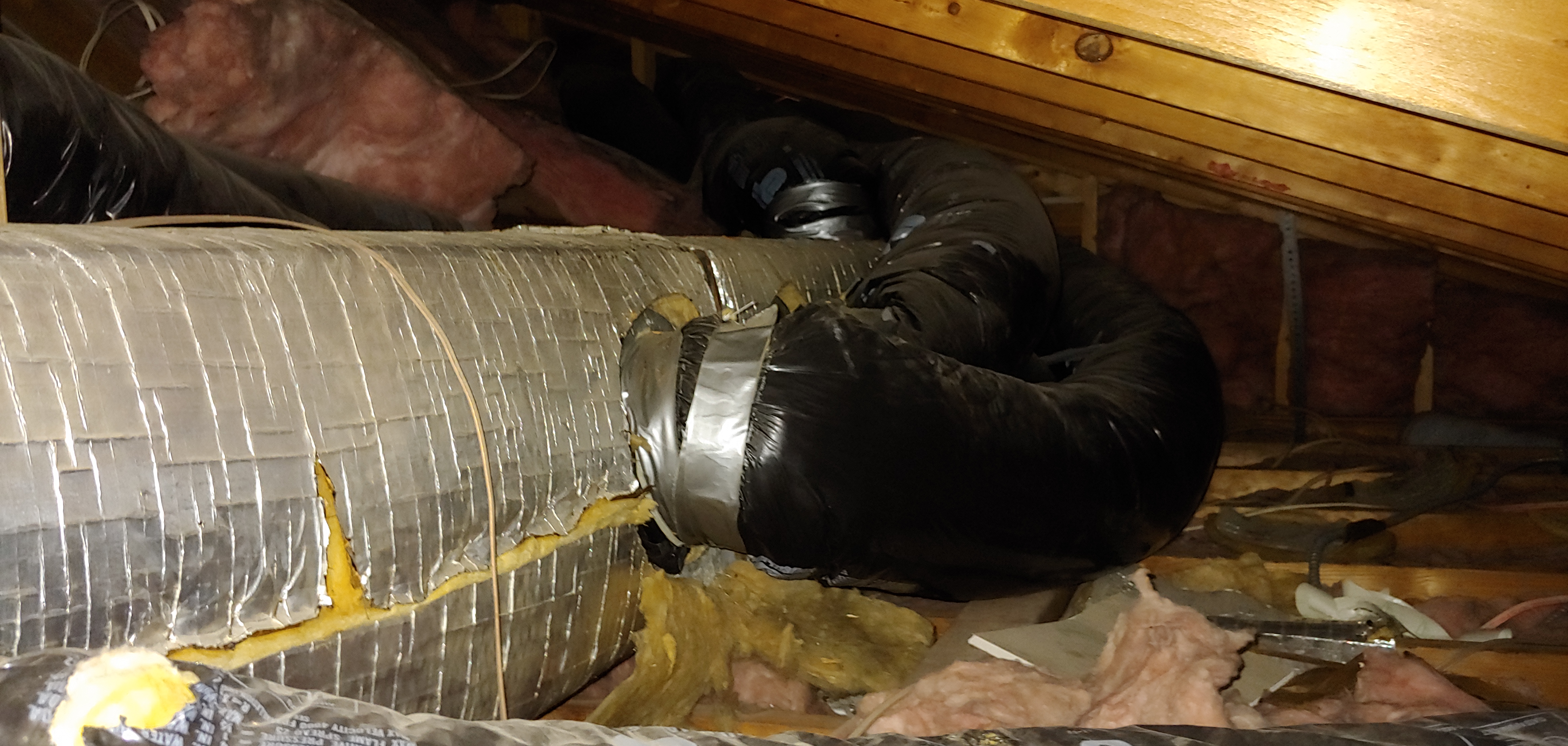
- Ensure that insulation completely covers ducts and connections without gaps, voids, or compressions.
- Consider insulating all metal ductwork located in conditioned space, including supply and return ducts, duct boots, and exhaust ducts, to minimize condensation.
See the Compliance Tab for links to related codes and standards and voluntary federal energy-efficiency program requirements.
Description
Ideally ducts should be located in conditioned space, such as within a dropped ceiling, between floors, in an insulated basement or crawlspace, or in an unvented attic that is insulated along the roof line. If ducts are located in an unconditioned space, such as a vented attic or vented crawlspace, they should be sealed and insulated to prevent heat loss due to air leaks and conduction and to provide some protection against harsh conditions.
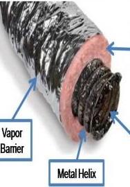
Flex duct consists of a plastic inner liner attached to a metal coil that comes already covered with a layer of fiberglass blanket insulation, which is covered by foil or plastic vapor barrier. It is typically available in R-4, R-6, and R-8. The 2009 IECC (Section 403.2) requires that supply ducts located in unconditioned space be insulated to at least R-8 (return ducts can be insulated to R-6).
Insulation
Whenever ductwork is located in unconditioned spaces, thermal insulation with a vapor barrier is a must to prevent unnecessary heat gain or loss through the duct walls and to prevent condensation from forming on the ducts themselves. For the insulation to work properly, it must be fully aligned and in contact with the walls of the duct system. A typical vented attic with a dark shingle roof can reach summer temperatures of 140ºF. At the same time, the dew point temperature in the attic will be about the same as it is outdoors. In humid climates, "duct sweating" can become a significant problem if the duct’s thermal and vapor barriers are not properly aligned along the entire length of the duct. Because the insulation is an integral part of the duct with flex ducts, insulation alignment is not an issue along the duct length but can be a problem at connections, if the insulation layers are not properly connected.
Sealing
Duct leakage is a double hit on the utility bill: 1) duct leaks are an uncontrolled loss of conditioned air to the outdoors and 2) duct leakage drives building infiltration. For example, if a home had a 2.5-ton (30,000 BTU/H) cooling system moving 1,000 CFM (cubic feet per minute) of air and the ducts had 10% leakage (which is typical in code-built homes), the leakage rate would be 100 CFM. Each cubic foot of air carries with it 30 BTUs/H, so 3,000 BTUs of conditioned air would be lost to the outdoors each hour.
Duct leakage is an infiltration driver; it can negatively or positively pressurize the house depending on where the ducts are leaking, pulling outside air in through cracks in the building envelope or pushing conditioned air out. If the duct leakage is in the supply-side ducts, the house will be negatively pressurized compared to outdoors. If all the leakage is on the return side, the building will be positive with respect to outdoors. The field technician should understand this concept to help accurately detect any sources of duct leakage.
Unlike solid sheet metal and ductboard, flex duct is essentially seamless along its length and at bends so, as long as the ducting is not torn or punctured, the only place where air sealing is a concern is at connections. If connected properly, a correctly designed flex duct system can provide efficient air delivery for many years.
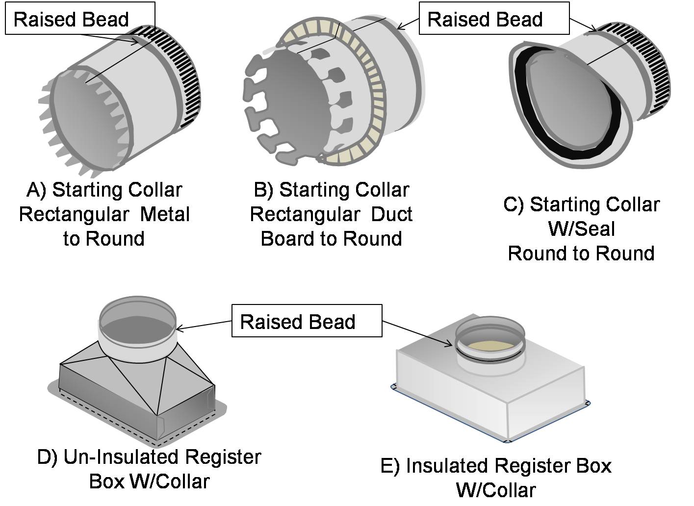
While there are several types of connections, all flex duct connections require similar practice to ensure proper air sealing, regardless of whether the flex duct is connected directly to the air handler box, to a trunk line, to a junction box connected to the trunk line, or to a supply register. All connections use a round metal connector called a collar, which is either purchased at a supply house or made in the HVAC contractors’ metal shop. A raised metal bead encircles the collar at the end (see Figure 1). The raised bead can be located anywhere from 2 inches to 1/2 inch from the end of the collar. When the flex duct is pulled over this bead and secured with a nylon draw band, the raised bead prevents the duct from slipping off the end of the collar.
Figure 1 shows three types of starting collars and two register boxes (also known as duct boots) with collars attached. Collar A attaches flex duct or round metal duct to a rectangular metal box such as the air handler box or a metal trunk line. Collar B is for attaching a flex duct to a rectangular ductboard box or trunk line. Collar C is for attaching round flex duct or round metal duct to a round trunk line. Images D and E show uninsulated and insulated register boxes that are purchased with the collars pre-attached. If uninsulated boxes are purchased, they can be insulated on site by wrapping them with R-8 blanket insulation. Notice that all five collars have the raised bead. This type of connection (with raised beads on each end) can also be used to splice two pieces of flex duct together, a practice used to save on materials costs rather than throwing away short pieces of duct.
After the inner liner and coil are secured, the insulation and outer liner are secured and the seam is made air tight with metal tape and mastic. The metal tape should meet the requirements of the Underwriters Laboratory UL-181, UL-181A, or 181B (CEC 2005). Regular cloth-backed duct tape should not be used because it can dry out and fail quickly. Mastic is a thick, gooey, non-hardening substance that is spread onto the duct seams with a paintbrush or a putty knife.
For more on flex duct installation, see No Kinks or Sharp Bends in Flex Duct Installation, No Excessive Coiled or Looped Flex Ducts, Sufficient Cavity Space for Flex Ducts, Support at Intervals for Flex Ducts, Building Cavities not Used as Supply or Return Ducts, and HVAC Ducts Shall Not Be Run in Exterior Walls.
Duct installation standards and installation guidance are also provided in ACCA Manual D Residential Duct Systems published by the Air Conditioning Contractors of America (see Appendix 17 for a detailed discussion of duct installation) and the Flexible Duct Performance Standards (Fifth Edition) published by the Air Diffusion Council (ADC).
How to Seal and Insulate Flex Duct at a Collar Connection
- Pull the end of the flex duct over the end of the collar, pulling the flex duct core at least 2 inches past the raised bead.
Push back the outer liner and insulation.

Figure 2. To attach the flex duct to a main trunk duct or any other connection, the flex duct is pulled over the connecting collar at least 2 inches past the raised bead, then the insulation is pulled back. Wrap the nylon draw band around the duct over the inner liner, above the raised bead.
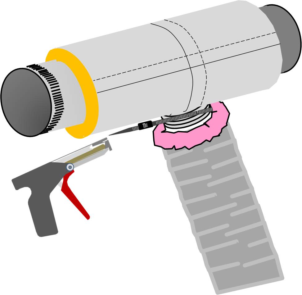
Figure 3. A nylon draw band and tensioning tool are used to secure the inner coil of the pre-insulated flexible duct. Thread the draw band through its locking system and tighten the nylon draw band with a tool specifically designed for this use, commonly known as a tensioning tool.

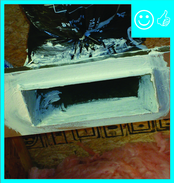
Figure 4. A nylon draw band and tensioning tool are used to secure the inner liner of the pre-insulated flexible duct. Seal the connection with mastic. Paint the mastic generously over the draw band, bridging from the inner liner to the collar.
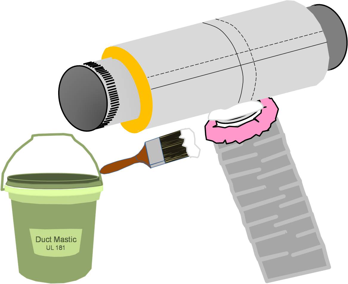
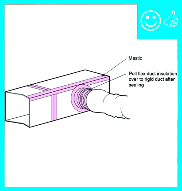
Figure 5. After securing the inner coil, cover the draw band and the seam with a generous amount of mastic. - Pull the insulation and outer liner of the flex duct up over the collar. Make sure the flex duct insulation comes in full contact with the insulation on the trunk line or fitting (such as a duct boot) that it is being attached to. Pull the outer liner of the duct up to the outer liner of the trunk line or fitting.
Tape the outer liner in place with UL-181- approved foil tape. Do not use a draw band to secure the flex duct insulation. It will compress the insulation, which could create cold spots along the exterior of the duct and possible condensation issues.
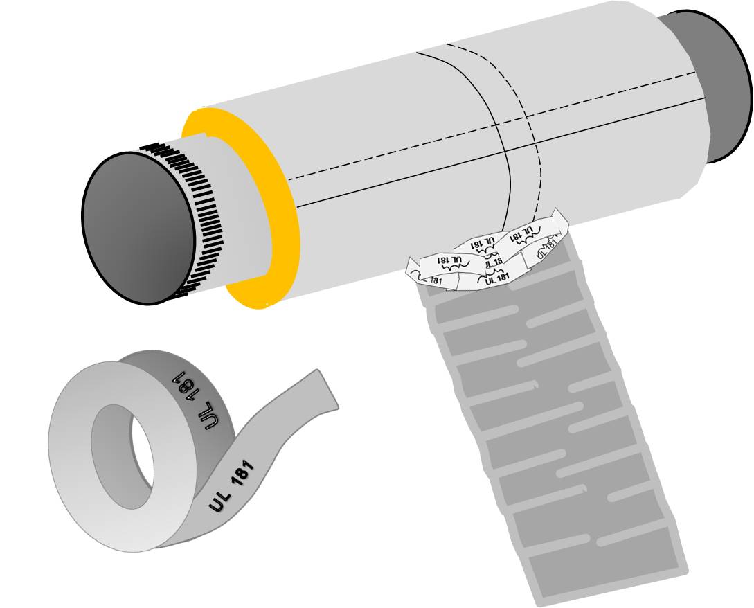
Figure 6. Pull the insulation and outer liner of the flex duct over the collar to come in full contact with the liner and insulation of the trunk line or fitting and tape in place. 
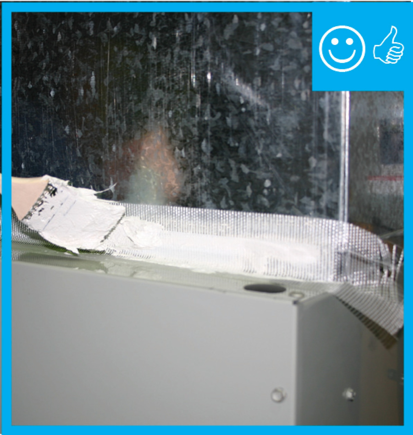
Figure 7. Use only Underwriters Laboratory UL-181 approved tape. Paint mastic over the foil tape making sure that the mastic bridges across the foil tape from the trunk line or fitting to the duct. As an alternative to foil tape, fiberglass mesh tape and mastic can be used to seal the seam in the outer liner.
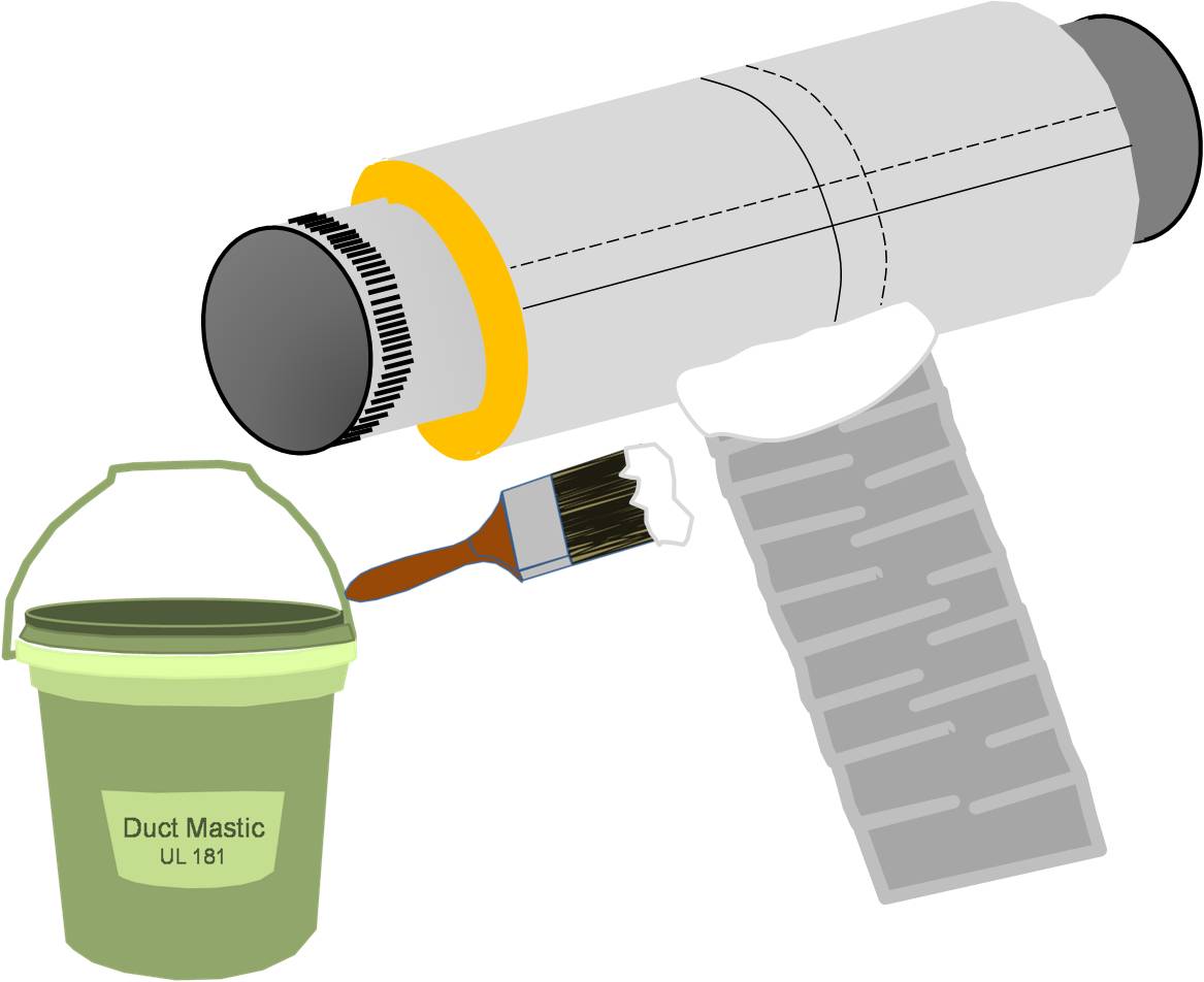
Figure 8. The tape is covered with mastic to ensure an airtight seal between the duct and the fitting.
How to Seal and Insulate Flex Duct at a Splice
Connect each end of the duct to a round sheet metal connecter of the correct diameter that is purchased or fabricated. If fabricated, it should be made with the machined raised bead at each end of the pipe to secure the connections.
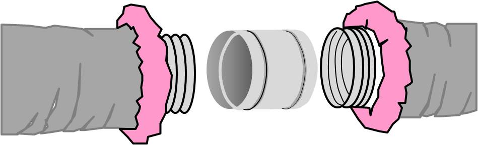
Figure 9. Two pieces of flex duct can be spliced together with a metal sleeve. Pull the ducts over the raised beads at each end of the connector, fasten the inner coils with nylon draw bands, mastic the seams, then pull together the insulation and outer liners, tape the seams together, and cover the tape with more mastic. - Join each piece of flex duct to the connector and secure the inner liner using a draw band, as described in steps 2 through 6 above.
- Pull the insulation together and ensure that it meets all the way around the pipe.
- Pull together the exterior liner and attach with foil tape.
- Seal the connection with mastic.
Ensuring Success
After ducts are installed and before drywall is installed, the duct system should be visually inspected by a HERS rater to ensure that all connections are properly fastened and sealed, preferably with mastic, and completely insulated. The following connections should be inspected: the main supply trunk to the branch duct, the branch duct to the duct boots, duct splices, the return ducts to the return box, jump duct connections, and exhaust fan and ERV/HRV connections. HVAC ducts should be tested for air leakage and proper air flow with a duct blaster test. This test should be done before drywalling when any air leaks can still be accessed and sealed. The ducts should be inspected to confirm that the proper amount of insulation is installed (minimum R-8 for supply ducts and R-6 for all other ducts) and that the insulation is not compressed by tight strapping, by framing members or other obstacles, or by excessive bending.
Region
No climate specific information applies.
Training
Right and Wrong Images
Source

Source
Source


Source
Source
Source
Source
Source
Source
Videos

Compliance
Retrofit
SCOPE
Additions
If new flex duct is added to an existing home, as part of either an addition or an equipment upgrade, ensure that the flex duct is installed in runs that are as short, straight, and direct as possible, and that they are well air sealed and insulated, as described in the Description tab.
Existing Buildings
In an existing building with flex duct and an under-performing HVAC system, inspect for lack of air sealing and adequate insulation. Symptoms of inadequately installed, sealed, or insulated flex duct may include poor comfort control and excessive energy use. Before sealing or adding insulation to flex ducts, check to make sure flex duct runs have no excessive coils or loops and that the duct wall has not collapsed due to kinks or sharp bends. Flex duct runs should be limited in length and the duct should be pulled taut to reduce internal airflow friction. See the following guides to remedy installation problems prior to sealing or adding insulation to an existing flex duct system:
For more information, view the U.S. Department of Energy’s Standard Work Specifications regarding ducts.
If the ducts are located in the attic, review the guide Pre-Retrofit Site Assessment of Attics, Ceilings and Roofs.
If the ducts are located in the basement or crawlspace, review the guide Pre-Retrofit Site Assessment of Crawlspaces and Basements.
DESCRIPTION
Insulation
Whenever ductwork is located in unconditioned spaces, thermal insulation with a vapor barrier is a must to prevent unnecessary heat gain or loss through the duct walls and to prevent condensation from forming on the ducts themselves. For the insulation to work properly, it must be fully aligned and in contact with the walls of the duct system. A typical vented attic with a dark shingle roof can reach summer temperatures of 140ºF. At the same time, the dew point temperature in the attic will be about the same as it is outdoors. In humid climates, "duct sweating" can become a significant problem if the duct’s thermal and vapor barriers are not properly aligned along the entire length of the duct. Because the insulation is an integral part of the duct with flex ducts, insulation alignment is not an issue along the duct length but can be a problem at connections, if the insulation layers are not properly connected.
Sealing
Duct leakage is a double hit on the utility bill: 1) duct leaks are an uncontrolled loss of conditioned air to the outdoors and 2) duct leakage drives building infiltration. For example, if a home had a 2.5-ton (30,000 BTU/H) cooling system moving 1,000 CFM (cubic feet per minute) of air and the ducts had 10% leakage (which is typical in code-built homes), the leakage rate would be 100 CFM. Each cubic foot of air carries with it 30 BTUs/H, so 3,000 BTUs of conditioned air would be lost to the outdoors each hour.
Duct leakage is an infiltration driver; it can negatively or positively pressurize the house depending on where the ducts are leaking, pulling outside air in through cracks in the building envelope or pushing conditioned air out. If the duct leakage is predominantly in the supply-side ducts, the house will be negatively pressurized compared to outdoors. If the leakage is predominantly on the return side, the building will be positive with respect to outdoors. The field technician should understand this concept to help accurately detect any sources of duct leakage.
For the installation of flex duct in retrofit and existing building situations, follow all best practices and precautions described for new construction. Poor comfort control and wasted energy occur when conditioned air doesn’t make it all the way to the target space (due to leakage in the system) or when the target temperature of the conditioned air is compromised (due to heat gain or heat loss through uninsulated ductwork.) Additionally, duct leakage can drive infiltration, increasing the entrance of uncontrolled outdoor air that requires conditioning.
Note that the physical connections of all ducts must be properly air sealed before the addition of insulation. Fasten the inner liner to the collar with mechanical fasteners and seal with tape or mastic. Cover with insulation and a plastic sheeting vapor barrier and seal the plastic to the trunk duct or boot collar with metal tape or mastic, as described in the guide Duct Sealing for detailed sealing guidance.
Additions
Coordinate the duct layout for a new space with the design of the structure and other systems to ensure there is space for proper routing. As with new construction, use ACCA Manual D and provide a drawing of the layout to the homeowner for future reference.
Existing Buildings
See Pre-Retrofit Assessment of Existing HVAC Systems for a discussion of how to determine whether a flawed duct design may be contributing to poor HVAC system performance.
ENSURING SUCCESS
When re-routing ductwork, access the ducts directly from the basement, crawlspace, or attic if possible. If the ducts are behind finish materials like drywall, it is tempting to make the smallest possible openings in existing ceilings and walls in an effort to reduce disruption. However, flex duct is likely to collapse if forced into place from a distance. It will be impossible to fully examine the entire duct layout if openings are too small. Instead, cut openings in drywall large enough to fit head and shoulders so that the flex duct can be manipulated into the best possible orientation.
Starting with the 2009 International Energy Conservation Code (IECC), supply ducts located in unconditioned space must be insulated to at least R-8, and return ducts must be insulated to R-6.
Although an existing duct system is generally not required to be brought up to code when making repairs (double check this with the local code official), you can take this opportunity to check the ducts for duct leakage and seal all accessible seams and joints; use outward-clinched staples and UL-181A-approved metal tape that is heat activated or pressure sensitive or use mastic and fiber mesh tape. You can also add duct insulation where it is lacking or deficient, especially if you see evidence that condensation has been occurring.
COMPLIANCE
See Compliance tab.
More Info
References and Resources
*For non-dated media, such as websites, the date listed is the date accessed.
Contributors to this Guide
The following authors and organizations contributed to the content in this Guide.
Sales
High-R Duct Insulation
Technical Description
Without adequate duct insulation, there can be significant heat loss or heat gain as conditioned air travels through the comfort delivery system. This is especially true where ducts are located in an uninsulated attic or crawlspace. Insulation significantly reduces this energy loss and helps ensure conditioned air is effectively distributed from the comfort equipment to a home’s living spaces.
Questions? Comments? Contact our webmaster.