

Scope
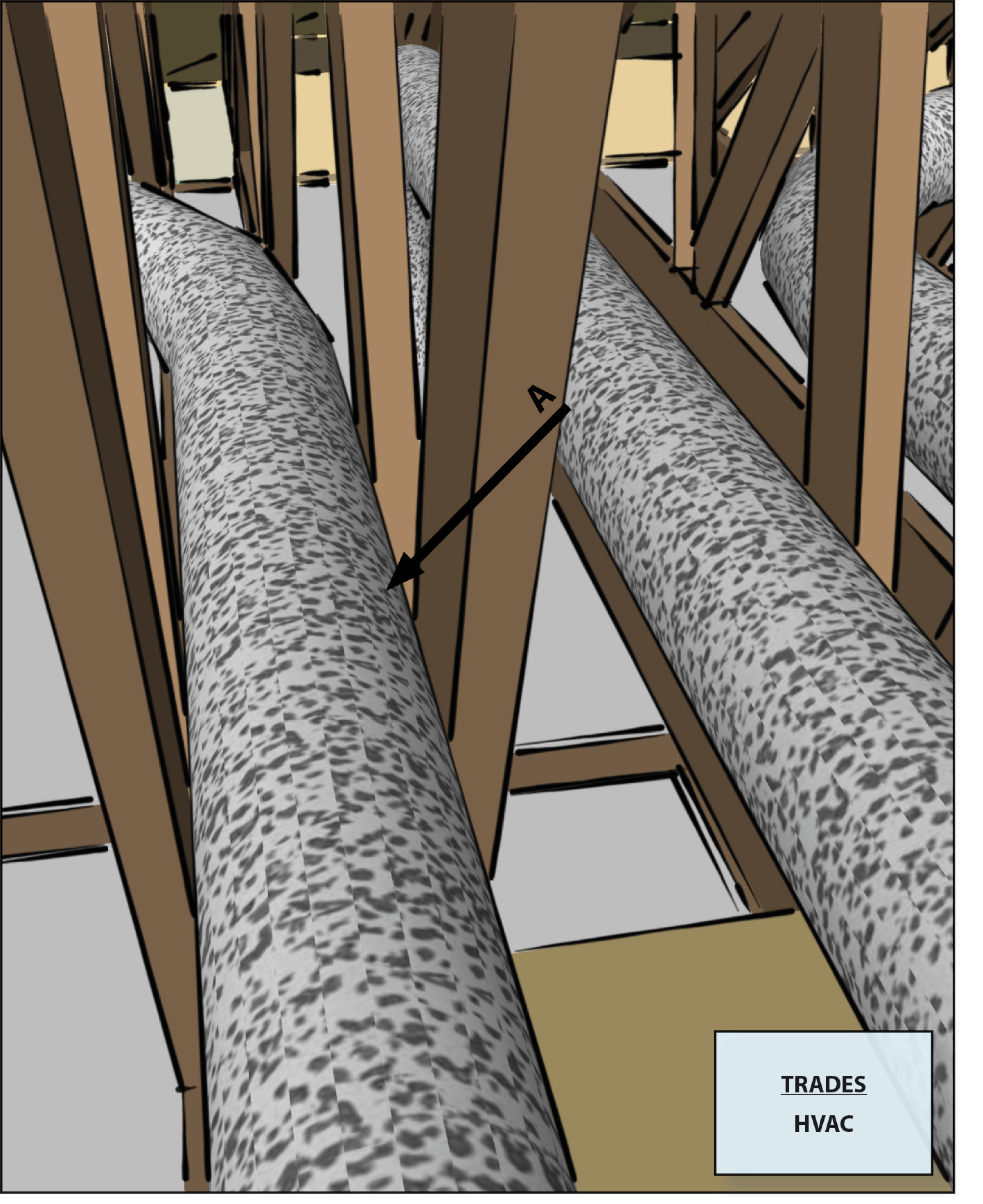
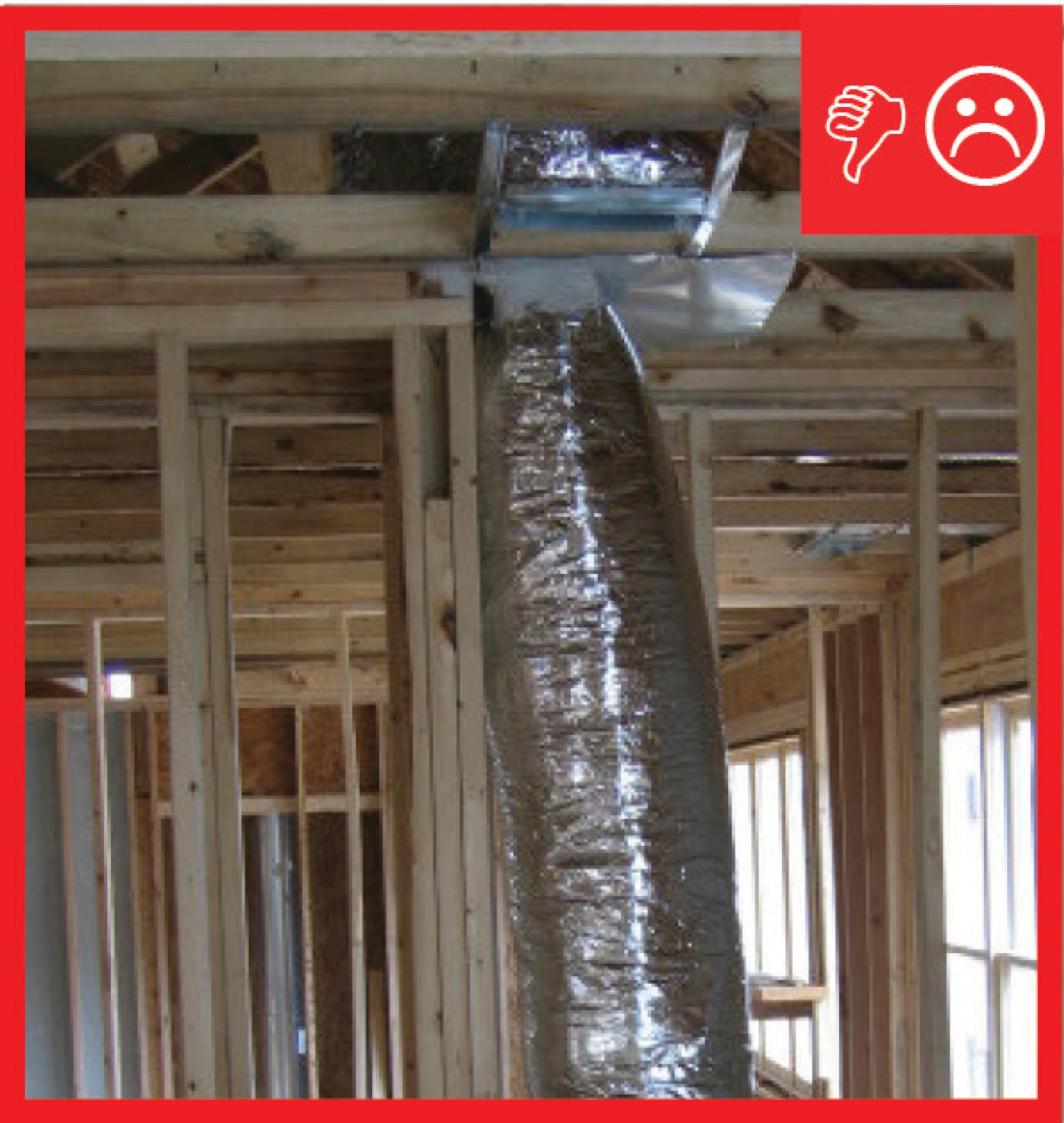
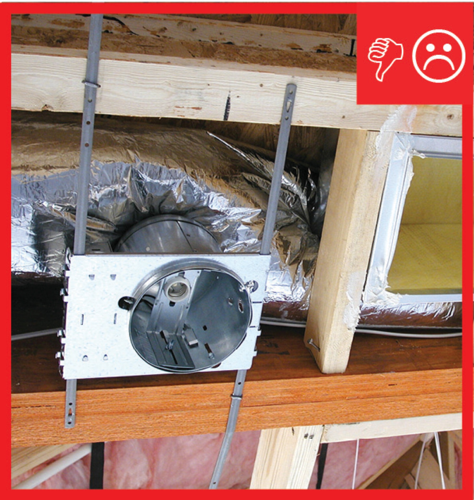
Ensure that flex ducts are not located in building cavities where they will be compressed or crushed.
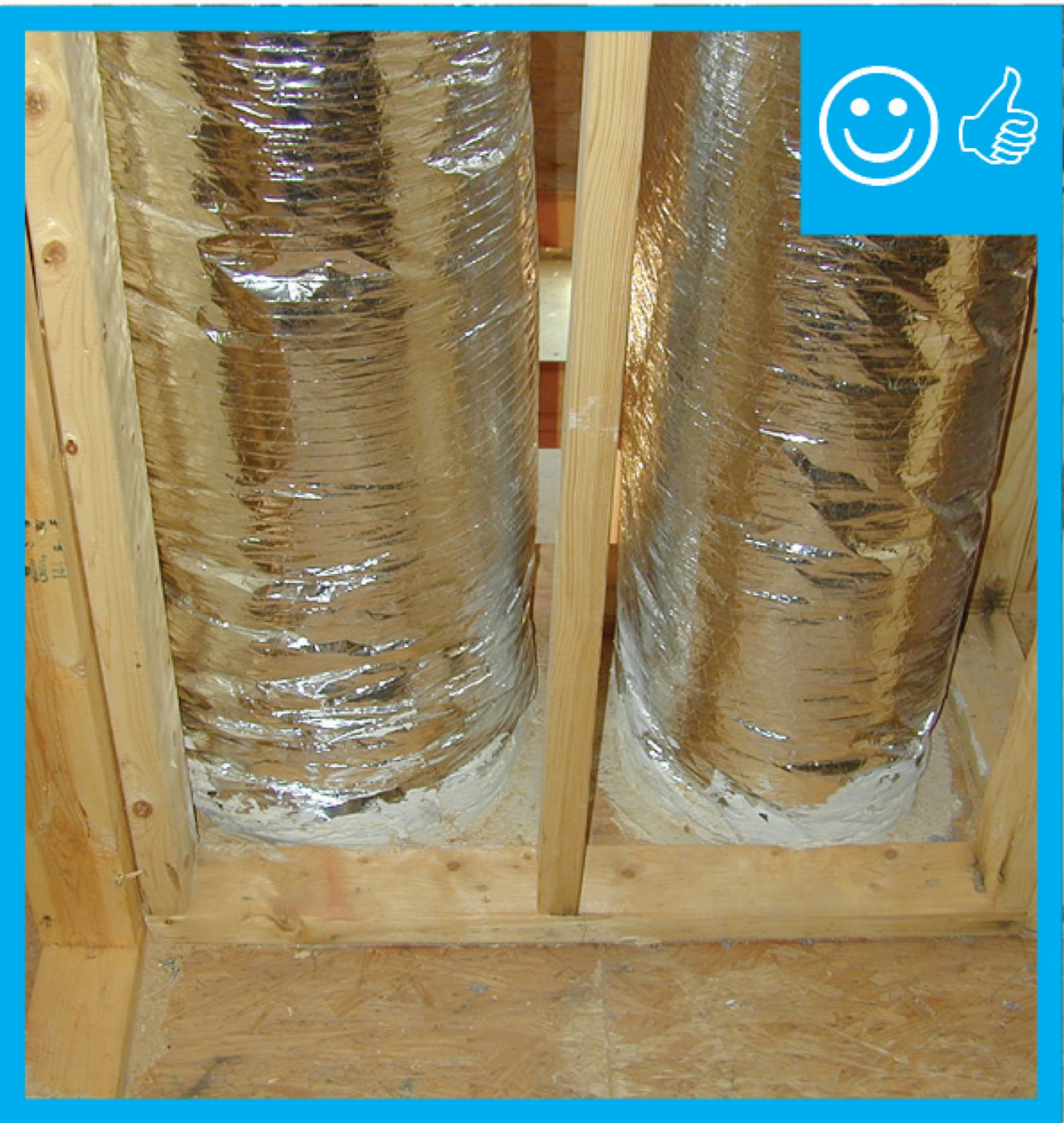
When flexible ducts are installed in unconditioned areas of the home, they should not be squeezed into any cavities that are smaller than the outer diameter of the duct, including the duct insulation; in conditioned space, they should not be installed in cavities smaller than the inner duct diameter (ENERGY STAR).
- Consider duct layout in the initial framing design stage to plan for short, straight duct runs with no compressions.
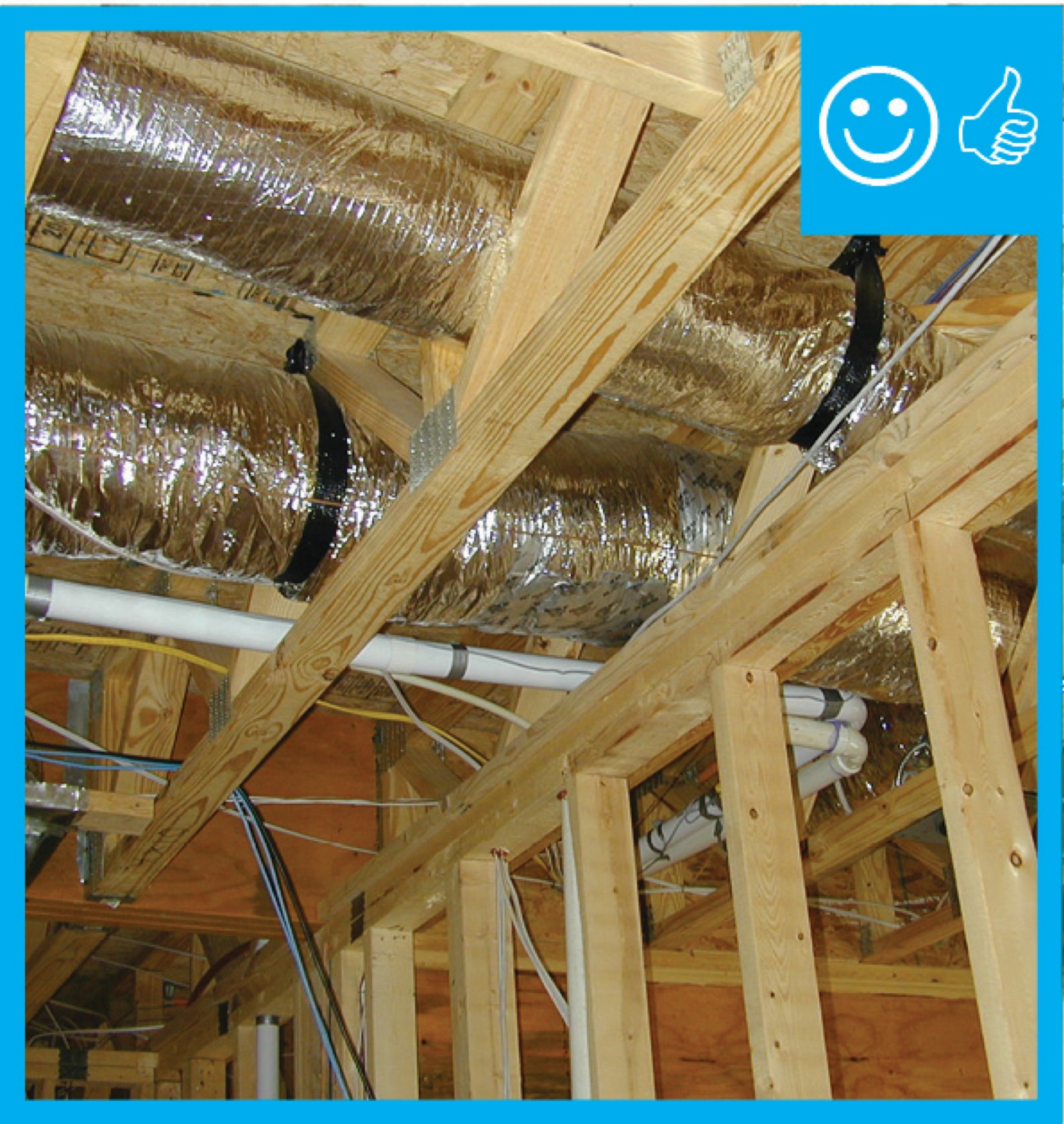
- Install flex duct in the straightest line possible; pull ducting taut and provide adequate supports per code.
- Ensure that the radius of each bend is no less than the diameter of the flexible duct.
- Coordinate with the plumber and the electrician to avoid crushing ducts when other services are installed.
- Design ducts in compliance with Manual D.
See the Compliance Tab for links to related codes and standards and voluntary federal energy-efficiency program requirements.
Description
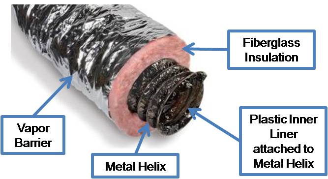
Flexible duct, known as flex duct, is very convenient ducting for attaching supply air outlets to rigid trunk ductwork, and, in many cases, flex duct comprises the entire duct system. Flex duct made for HVAC applications is typically constructed of a plastic inner liner attached to a metal wire helix (or coil) to make round, flex duct. The duct comes with a layer of fiberglass blanket insulation already attached around the duct. The insulation is covered and protected by a polyethylene or foil vapor barrier. Flex duct is typically available in insulation values of R-4, R-6, and R-8. For residential HVAC systems, insulated flex duct typically comes in diameters of 4 inches through 10 inches; above 10 inches, it comes in even sizes of 12, 14, 16, etc., up to 22 inches measured at the radius of the metal helix.
For proper performance, flex ducts in unconditioned space should not be installed in cavities smaller than the outer diameter of the duct, including the insulation. Compression of the insulation around the duct should be avoided, especially in humid climates where compressed insulation could encourage condensation to form. Even when ducts are installed in conditioned space, they should not be installed in cavities smaller than the inner duct diameter.
During the design phase, duct routing should be identified. Open-web trusses between floors allow for ducts to freely pass through the floor system without compromising the structure. Manual J and D calculations should be performed to identify the size of ducting needed and thus how much space is required for the ductwork. Remember to take into account the thickness of the insulation (Figure 2). For example, if R-6 flex duct is used, then the exterior diameter of the duct will increase by four inches. Plan air handler locations, making sure there is clear access for the flex duct (or other specified ducting) to run from the mechanical space (or room) to the duct zone (Figure 3). Manual D Residential Duct Systems (ACCA 2009) sets standards for flex duct design and installation. See Appendix 17 for a detailed discussion of duct installation. The Flexible Duct Performance Standards (Fifth Edition) by the Air Diffusion Council (ADC) provides guidance to designers, architects, engineers, contractors, and installers.
For more on flex duct installation, see No Kinks or Sharp Bends in Flex Duct Installation, Support at Intervals for Flex Ducts, No Excessive Coiled or Loped Flex Ducts and Sealed and Insulated Flex Ducts.
How to Install Flex Ducts within Appropriate Cavity Space
Design ducts in compliance with Manual D. Once the appropriate duct diameter is determined, establish the duct layout in coordination with the framing plan. Ensure that adequate space is allowed for all trunk and branch duct runs.
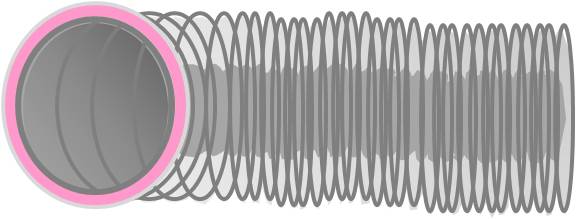
Figure 2. R-6 flex duct has 2 inches of insulation around the inner liner. If the required duct run is a 12-inch round, the exterior radius will be about 16 inches. At a minimum, a 16x16-inch duct chase or opening would be required along the full length of the duct. 
Figure 3. Ensure that the air handler location does not conflict with duct routing. 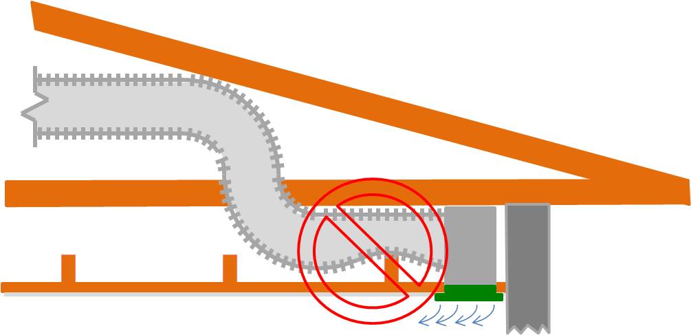
Figure 4. The height and width of a dropped soffit used to house ductwork should be the duct diameter plus the thickness of the insulation to prevent compression of the duct. If room is tight and there is fear of compressing the flex duct when making a 90-degree turn, use a metal elbow.

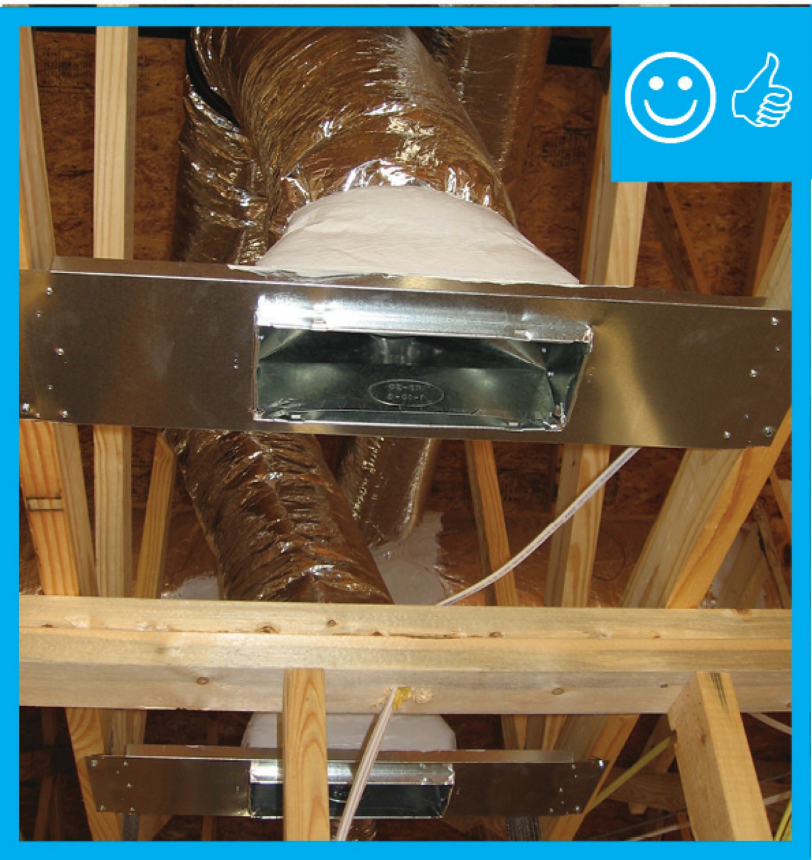
Figure 5. Use a metal duct elbow instead of flex duct at boot connections to prevent compressions. - Coordinate with the framer, plumber, and electrician for effective duct installation with adequate space.
Ensuring Success
Consider duct layout in the initial framing design stage to plan for short, straight duct runs where the duct is adequately supported and has adequate space to avoid constriction of flow. Inspect before drywall is installed to ensure that ductwork is not constricted. Use a duct blaster test to detect leakage and to confirm proper air flow at each duct supply outlet.
Region
No climate specific information applies.
Training
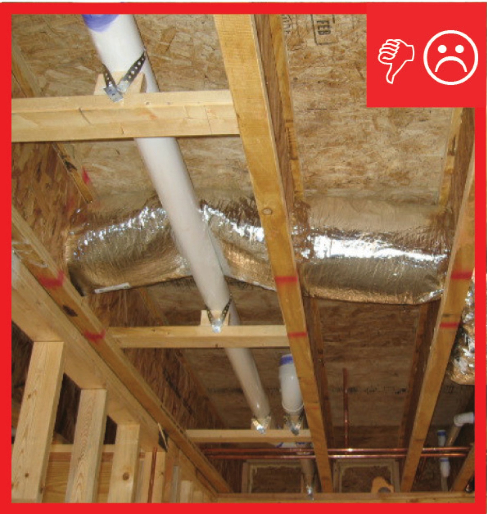
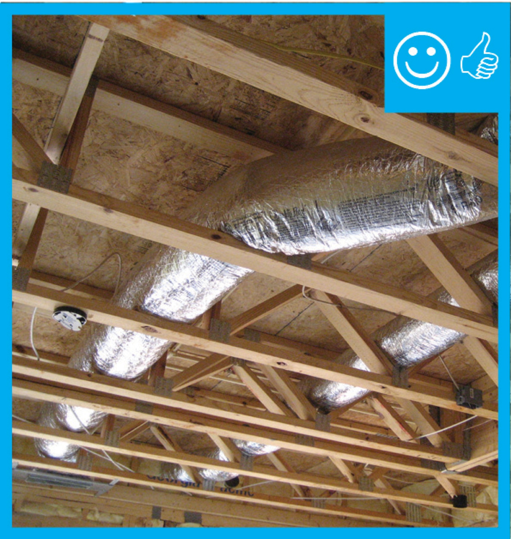
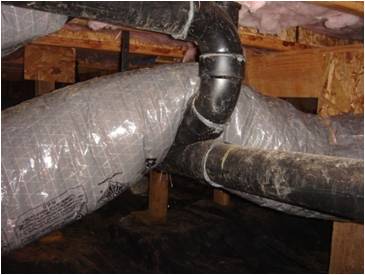
Right and Wrong Images
Source
Source
Source
Source

Source
Retrofit
SCOPE
Additions
If new flex duct is added to an existing home, either as part of an addition or an equipment upgrade, ensure that the flex duct is installed in runs that are as short, straight, and direct as possible and if any duct runs through building cavities verify that the cavities are large enough to have sufficient space to contain the duct without compressing it, as noted in the Description tab.
Existing Buildings
In an existing building with flex ducts and an under-performing HVAC system, inspect for compression of the flex duct. Symptoms may include minimal air flow to a terminal, excessive noise, or fan burnout due to increased static pressure.
If the ducts are located in the attic, review the guide Pre-Retrofit Site Assessment of Ceilings, Attics, and Roofs.
If the ducts are located in the basement or crawlspace, review the guide Pre-Retrofit Site Assessment of Crawlspaces and Basements.
For more information about ducts see the U.S. Department of Energy’s Standard Work Specifications.
DESCRIPTION
For the installation of flex duct in retrofit and existing building situations, follow all best practices and precautions described for new construction. A typical cause of crushed or kinked flex duct is a constricted route through building cavities that do not accommodate the shape and diameter of the flex duct. As with new construction, this can also happen at transitions such as at connections to the air handler and/or at the boots connecting a duct to a register or grille. Consider using a metal duct elbow instead of flex duct at boot and equipment connections to prevent compressions. Refer to installation images in the Description tab of this guide.
Additions
See Existing HVAC System Upgrade or Expansion for a discussion on when and how to add to an existing distribution system. Coordinate the duct layout for a new space with the design of the structure and other systems to ensure there is space for proper routing. As with new construction, use ACCA Manual D and provide a schematic of the layout to the homeowner for future reference.
Existing Buildings
See Pre-Retrofit Assessment of Existing HVAC Systems for a discussion of how to determine whether a flawed duct design may be contributing to poor HVAC system performance. If a flex duct is connected to a large, inflexible device or piece of equipment through a narrow cavity or opening, the flex duct will naturally collapse to conform to the obstruction or to fit the opening. Since it is often vital structure that causes the pinch-point, there are three alternatives:
- Re-route the duct. Consider offsetting the added static friction that results from the longer run by increasing the duct diameter. At a minimum, ensure all curves are gradual, fully extend the flex, and provide ample supports to prevent sagging.
- Move the duct by finding a new location for the supply register (sometimes possible) or for the obstacle (seldom possible).
A transition piece can be installed to fit the size and shape of the space. This can be accomplished with a non-flexible fitting in alternate dimensions that provides similar pressure drop. For instance, a round duct may transition to a flat rectangular shape to pass through a soffit constriction. This will require a well-sealed connection on each side of the new transition piece.
ENSURING SUCCESS
When re-routing ductwork, access the ducts directly from the basement, crawlspace, or attic if possible. If the ducts are behind finish materials like drywall, it is tempting to make the smallest possible openings in existing ceilings and walls in an effort to reduce disruption. However, flex duct is likely to collapse if forced into place from a distance. It will be impossible to fully examine the entire duct layout if openings are too small. Instead, cut openings in drywall large enough to fit the head and shoulders of the installer so that the flex duct can be manipulated into the best possible orientation. If flex ducts are disconnected, when reattaching them, fasten the inner liner to the collar with mechanical fasteners and seal with tape or mastic, then cover with insulation and the plastic sheeting vapor barrier and seal the plastic to the trunk duct or boot collar with metal tape or mastic, as described in the guide Sealed and Insulated Flex Ducts.
Although an existing duct system is generally not required to be brought up to code when making repairs (double check this with the local code official), you can take this opportunity to check the ducts for duct leakage and seal all accessible seams and joints with mastic and/or metal tape. You can also add duct insulation where it is lacking or deficient, especially if you see evidence that condensation has been occurring.
CLIMATE
Starting with the 2009 International Energy Conservation Code (IECC), supply ducts located in unconditioned space must be insulated to at least R-8, and return ducts must be insulated to R-6. Although an existing system is generally not required to be brought up to code (double check this with the local AHJ), this is the time to add insulation to deficient systems, especially if you see evidence that condensation has been occurring.
In humid climates, uninsulated or under-insulated ducts in unconditioned space can create a source of moisture damage. When warm, humid air comes in contact with the cold surface of a duct delivering chilled air, the water vapor can condense to liquid water that can cause rust in the ducts and mold in insulation, framing, and other building materials.
See Sealed and Insulated Flex Ducts for guidance.
COMPLIANCE
See Compliance tab.
More Info
References and Resources
*For non-dated media, such as websites, the date listed is the date accessed.
Contributors to this Guide
The following authors and organizations contributed to the content in this Guide.
Sales
Proper Duct Installation = Professionally-Installed Comfort Delivery Ducts
Technical Description
Conditioned air is often lost in transition from comfort equipment to living spaces because of poorly designed duct layouts and poor installation practices, which cause homeowners to pay for conditioned air that never reaches the living spaces of their home. Poor duct layouts with overly long duct runs, numerous branches, and sharp bends, and poor installation with sagging, twisted, or crushed ducts, can severely limit air flow, reducing system performance and increasing energy costs. Professionally installed comfort delivery systems should be installed with compact duct layouts featuring short, straight duct runs with properly supported ducts, in accordance with industry standards. The ducts should be properly insulated, completely air sealed, and free from kinks and sharp bends that restrict air flow.
Questions? Comments? Contact our webmaster.