

Scope
Air-seal and insulate the rim and band joists of walls separating an attached garage from the home’s conditioned space.
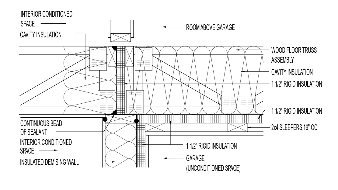
- Design the garage so that floor joists run parallel to the wall separating the garage from the living space forming a natural air barrier or use a rigid air barrier material to block open rim joists. Rigid air barrier materials could include rigid foam insulation, drywall, plywood, or OSB, among others.
- Air-seal any seams, gaps or holes in the rim joist or joist bay blocking material using caulk or foam.
- Insulate the rim joist area to code-required levels using rigid foam, spray foam, or a combination of rigid or spray foam and batt insulation.
- Ensure that the air barrier is continuous and in full contact with the insulation.
- If spray foam insulation is used for the wall cavity insulation, the spray foam can serve as the air barrier if it is at least 5.5 inches thick if open-cell or at least 1.5 inches thick if closed-cell spray foam insulation.
- ENERGY STAR requires that an air barrier be installed at the exterior vertical surface of the wall insulation in all climate zones and also that an air barrier be installed at the interior vertical surface in IECC Climate Zones 4-8 (ENERGY STAR).
See the Compliance Tab for links to related codes and standards and voluntary federal energy-efficiency program requirements.
Description
Attached garages can be a significant source of indoor air pollutants. Fumes from cleaning chemicals, garden fertilizers, pesticides, and vehicle exhaust are among the many contaminants that can be drawn into homes from attached garages if the walls and doors between the home and the garage aren’t adequately air-sealed. Open joist bays above the garage that extend into living spaces are one air pathway. Airflow through cracks between and around the boards of the rim joist, the top plate, and the sill plate-foundation wall intersections are other areas where air can flow through if seams aren’t adequately sealed. Certain conditions in the home can cause the home to become depressurized, making it even more likely for garage air to be drawn into the home through leaks in and around the rim joists. Depressurization can occur when the house is airtight and an exhaust fan, range hood, clothes dryer, or combustion appliance is operated, if adequate makeup air is not provided to the house through a fresh air intake (a duct that brings outside air to the return side of the air handler).
For occupant health and safety, consider designing homes with detached garages. If attached, the garage should be completely air-sealed from the living areas of the house. When garage ceiling joists span both the living space and the garage, the joist bay cavities must be blocked off and sealed. It is preferable to design the garage so that rim joists run parallel with the adjoining wall to act as a natural air barrier. The rim joists should be insulated and all seams where components (including the rim joist, top plate, and subfloor) come together should be sealed with caulk, spray foam, or foam gaskets. Seams between the bottom plate and the slab of the adjoining wall should also be caulked, foamed, or gasketed. This air-sealing could be done by the framer or the insulation installer. This task should be included in the contract for the appropriate trade depending on the workflow at the specific job site.
If the air handler for a central furnace must be located in the garage, it should be in an air-sealed closet with a dedicated air intake for combustion, a flue that exhausts to the outside, and a fresh-air intake ducted from the outside to the return plenum so that it is not drawing garage air to circulate through the house. Do not have supply or return registers in the garage. Determine whether a garage exhaust fan is advisable.
Install carbon monoxide detectors inside the home.
How to Air-Seal the Rim Joist between the Garage and Living Space Using Rigid Foam
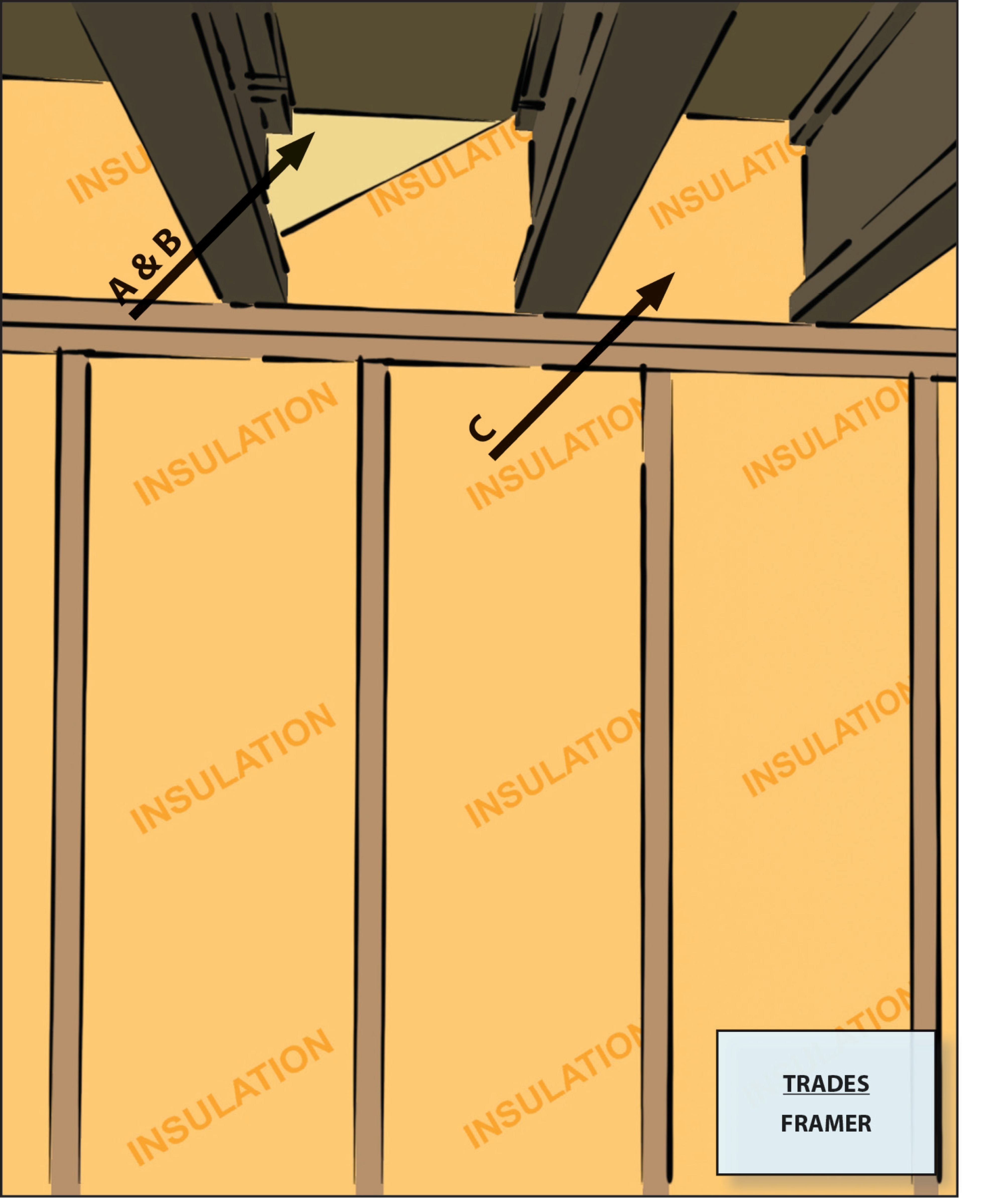
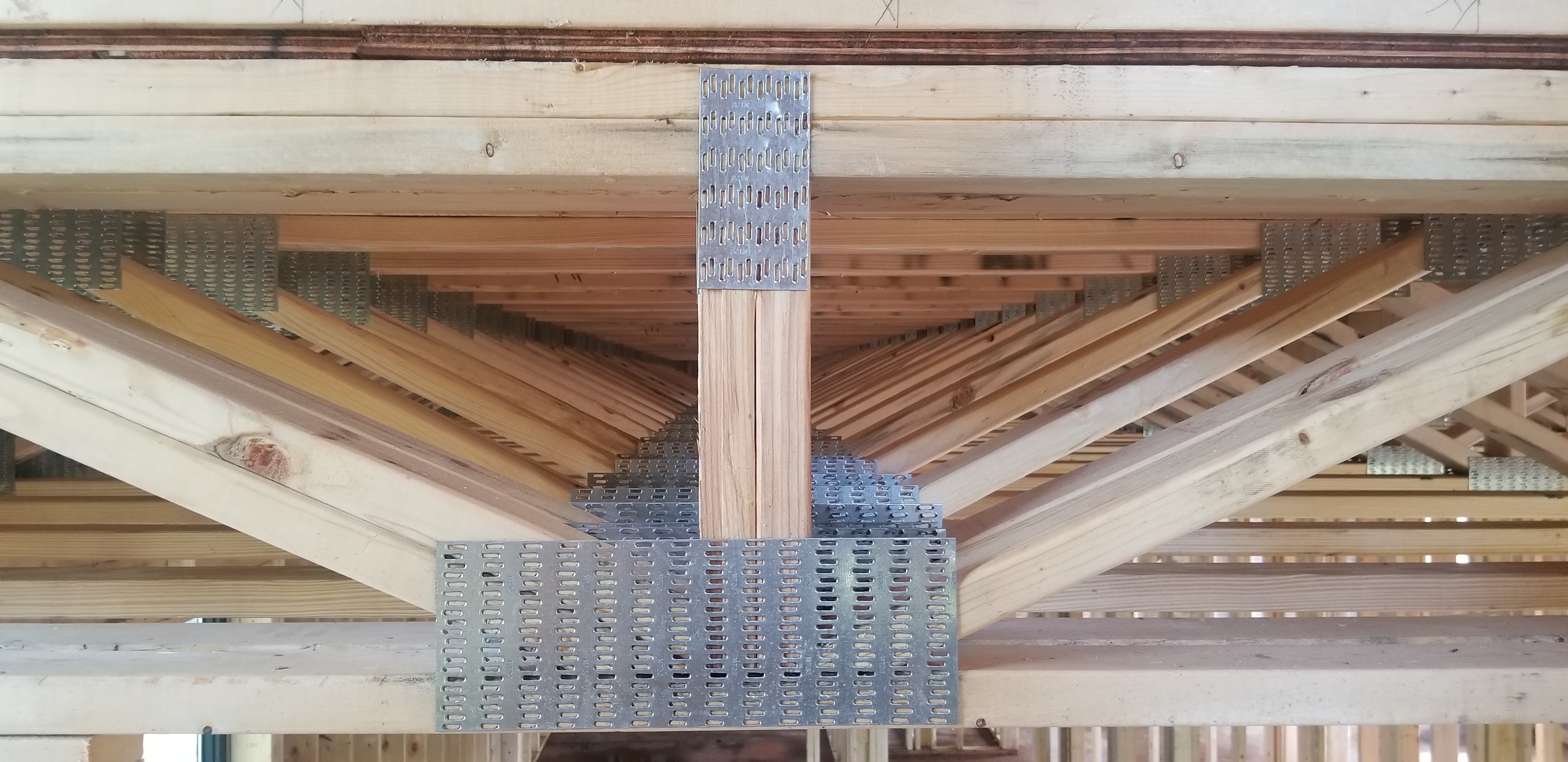
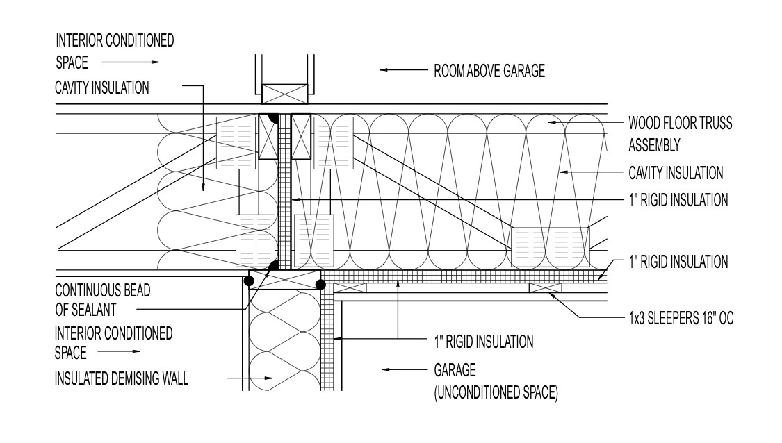
Design walls adjoining garages so that the rim joist board runs parallel to the wall, providing a continuous natural air break. Where ceiling joists run perpendicular to the adjoining wall, one option is to make the rim joist continuous and have separate but aligned ceiling joists on each side of the rim joist (Figure 1).
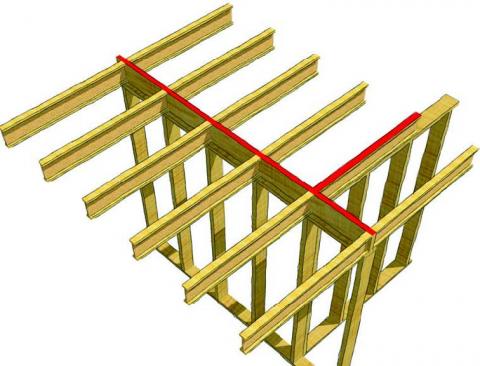
Figure 1. A continuous rim joist separates the garage ceiling joist bays from the living space ceiling joist bays. Cut a rectangle of rigid foam (polyisocyanurate or extruded polystyrene) to fit into each floor joist bay cavity. If the joist bay is open (Figure 2), make a backstop for the foam board by tacking furring strips to the framing in line with the foundation or house wall.

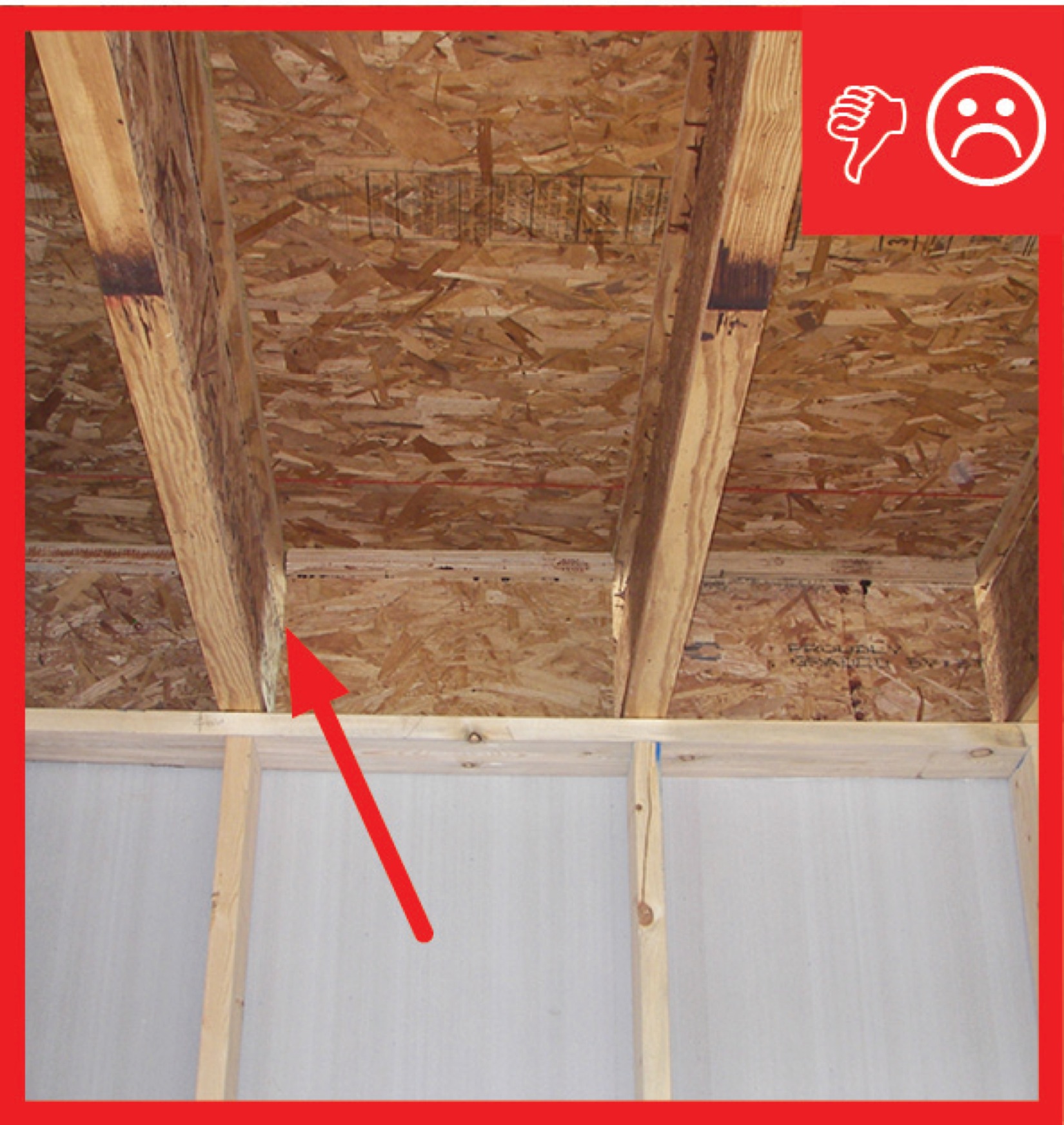
Figure 2. The ceiling joist bays above the garage wall are open to the adjoining living space. Insert rigid foam pieces into each joist bay (Figure 3).

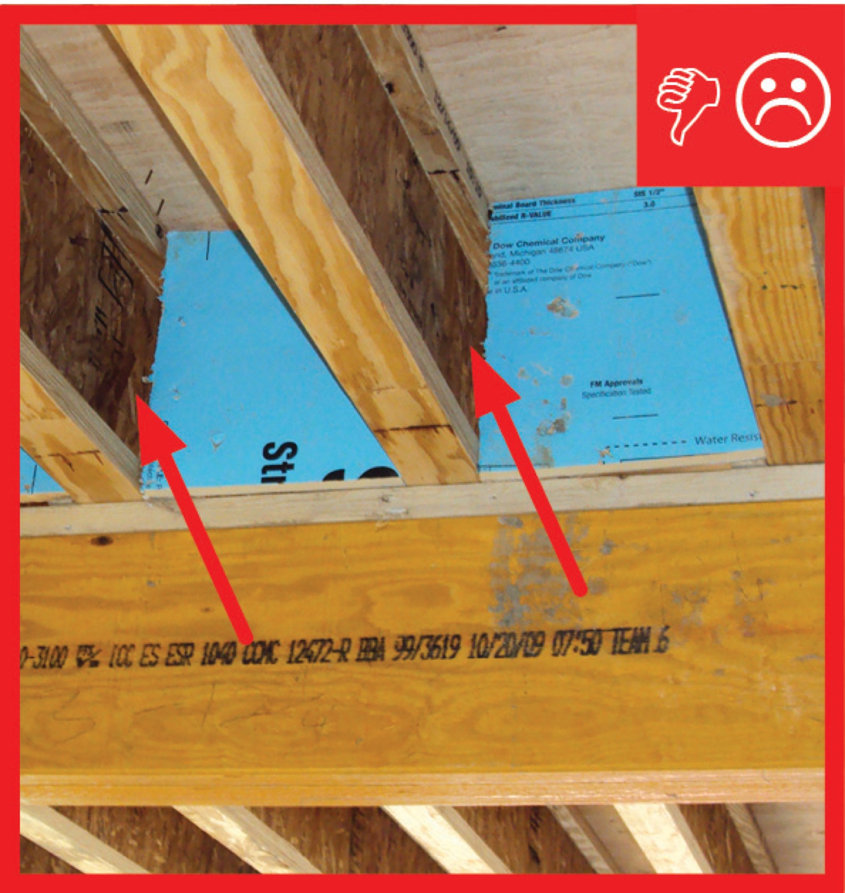
Figure 3. Fitting rigid foam in garage wall rim joist cavities to insulate and serve as an air barrier. Use caulk or spray foam to air-seal all four edges in each bay (Figure 4). Make sure to completely air-seal around the rigid foam to prevent moist air from reaching and condensing on the rim joist.

Figure 4. Caulk around each piece of rigid foam in garage wall rim joist cavities. - Add an additional layer of rigid foam or batt insulation to meet or exceed the code-required insulation level for an exterior wall.
How to Air-Seal the Rim Joist between the Garage and Living Space Using Spray Foam
Use urethane spray foam insulation to cover the rim joist and seam with the top plate or subfloor (Figure 5). Spray foams that are high density (closed cell, 2 pounds/cubic foot) or low density (open cell, 0.5 pounds/cubic foot) can provide acceptable results; open-cell foams might require additional vapor and condensation control measures in IECC Climate Zone 6 and higher. Foam can be applied by a spray foam subcontractor or by trades using two-part spray foam kits.
Spray foam in band joists is typically concealed between floors, so no other thermal barrier is required. However, the International Residential Code (2009 IRC and 2012 IRC R316.5.11) allows the spray foam at rim joists to be exposed (i.e., without a 15-minute thermal barrier such as drywall) as long as the thickness is less than 3-¼ inch, the foam has a density between 0.5 and 2.0 pounds per cubic foot (PCF), and the foam has a flame spread index of ≤ 25 and a smoke index of ≤ 450 when tested in accordance with ASTM E 84. High-density (closed-cell, 2-PCF) spray foams were approved in the 2003 IRC and low-density (open-cell, 0.5-PCF) foams were approved in the 2009 IRC, as well as any intermediate densities (BSC 2009).
Although open-cell spray foam is acceptable in this application, closed-cell spray foam is preferred in hot-humid or extreme cold climates (IECC Climate Zones 1A, 2A, 7, and 8) (CARB 2009).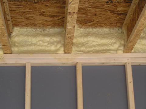
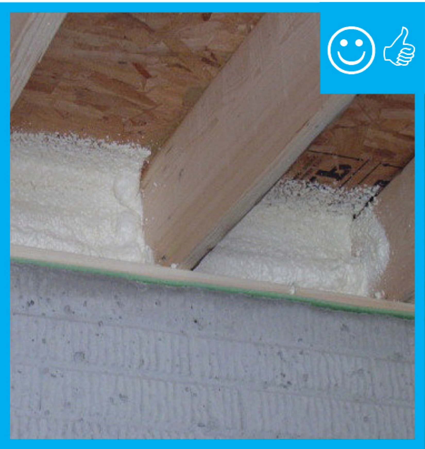
Figure 5. Spray foam insulates the rim joist and air-seals the subfloor-rim joist and rim joist-top plate connections. For additional protection when living space is located above the garage, consider a “flash” seal approach - spray the entire ceiling of the garage with a thin layer of foam to air-seal any cracks, holes, or seams in the subfloor. Then add batt insulation to meet the insulation R-value requirement (Figure 6). This reduces costs compared to filling joists to the required thickness with spray foam alone. Cover the ceiling insulation with taped and mudded drywall.
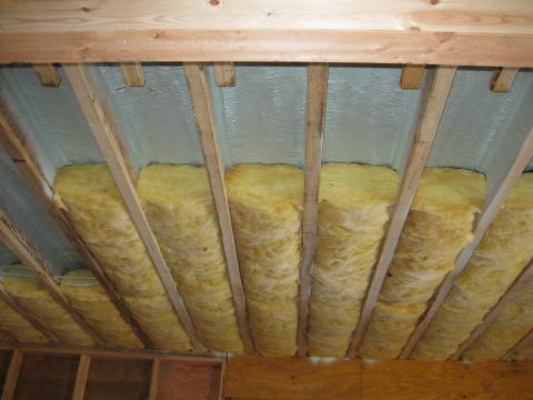
Figure 6. Garage ceiling with spray foam flash air-seal plus batt insulation.
Other Considerations
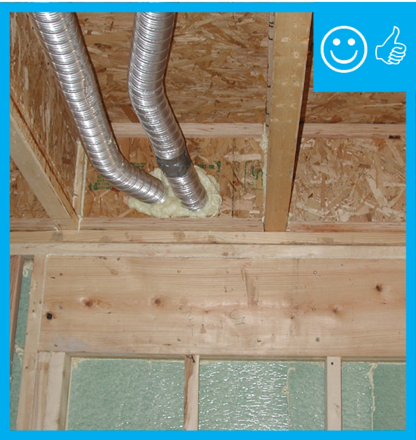
- Seal all penetrations through the common wall and ceiling. Use gaskets, airtight drywall technique, etc., to make the common wall and ceiling airtight. Caulk or spray foam the garage slab-foundation wall junction.
- Install a self-closing, insulated, metal, fire-rated door with a good weather seal between the living space and the garage.
- Install a passive roof vent to keep the garage at a negative pressure in relationship to the house or consider installing a timer-operated exhaust fan that vents to the outside.
- If the central HVAC system is installed in the garage, install a closed-combustion unit that draws intake combustion air from outside, vents exhaust air to outside, and has a fresh air intake ducted to the outside. Install the unit in an air-sealed closet. Mastic seal any ducts located in the garage. Do not install any return registers in the garage.
Ensuring Success
If the home has an attached garage, visually inspect for cracks or improper sealing along the rim joist above walls separating the garage from the home. For joist bays that extend from over the garage ceiling to over or under living areas of the house, the joist bay cavities should be blocked off at the common wall with a rigid air barrier that is caulked or foamed at all edges and insulated. Rim joists that run parallel to the shared wall should be air sealed and insulated..
Blower door testing conducted as part of the whole-house energy performance testing can indicate if the garage is sealed off from the house. It can also be used to determine whether the rim joists have been successfully air sealed. With the home depressurized, check for air leaks at the rim joist with a smoke pencil or infrared camera. Blower door testing can also help determine if the home is depressurized compared to the outside. If so, additional ventilation may be called for to prevent garage fumes from being pulled into the home.
The following actions are also recommended to ensure that garage air is separated from house air. Visually inspect for cracks along the base of garage walls that adjoin living space and along sill plates on top of foundation walls on adjoining walls. Visually inspect that all penetrations through adjoining walls and garage ceilings below living spaces are sealed. Test the seal tightness of doors linking the garage with the rest of the home. Visually inspect that furnaces installed in the garage have cabinets and ducts that are air sealed with mastic or metal tape or, preferably, that furnaces are installed in an air-sealed closet. No return air registers should be installed in the garage. Any ducts installed in the garage should be sealed with mastic and tested for air tightness.
Region
If the rim joists are to be sealed with spray foam, although both open-cell and closed-cell spray foam are acceptable in this application, closed-cell spray foam is preferred in hot-humid or extreme cold climates (IECC Climate Zones 1A, 2A, 7, and 8) (CARB 2009).
The map in Figure 1 shows the climate zones for states that have adopted energy codes equivalent to the International Energy Conservation Code (IECC) 2009, 12, 15, and 18. The map in Figure 2 shows the climate zones for states that have adopted energy codes equivalent to the IECC 2021. Climate zone-specific requirements specified in the IECC are shown in the Compliance Tab of this guide.

Training
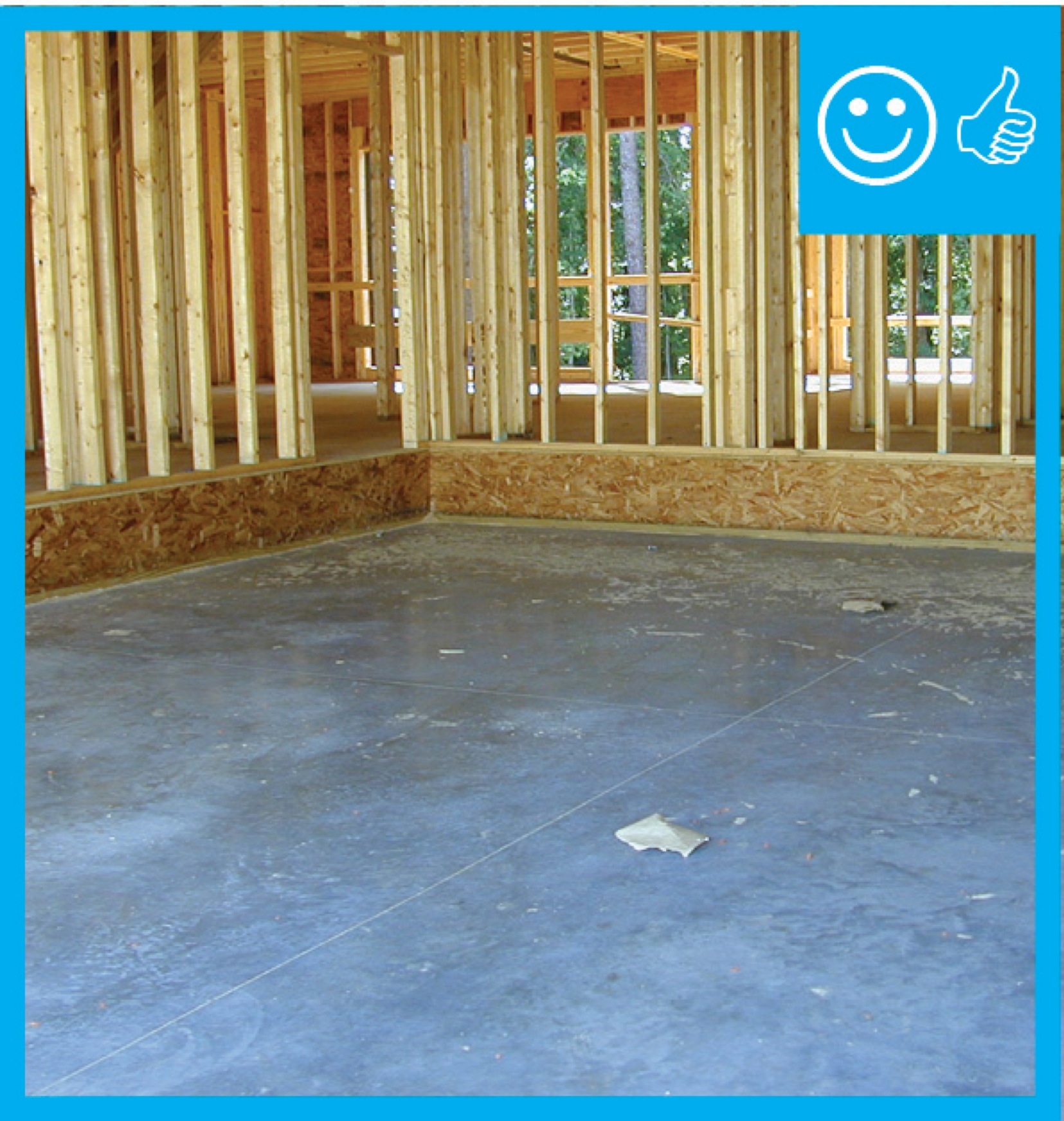
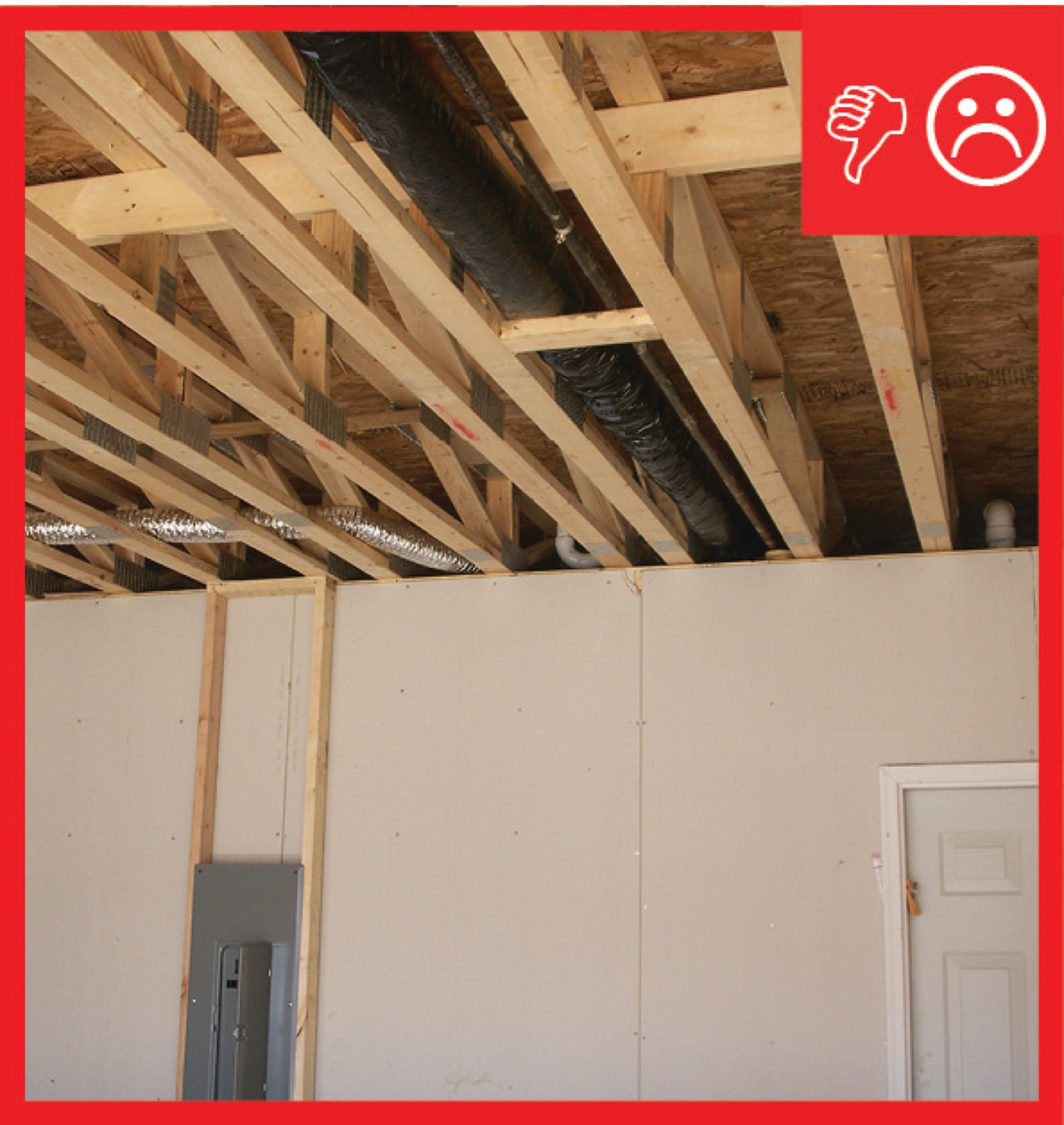
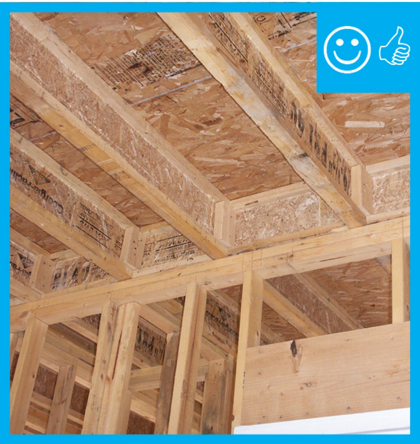
Right and Wrong Images

Source
Guide describing details that serve as a visual reference for each of the line items in the Thermal Enclosure System Rater Checklist.
Source
Guide describing details that serve as a visual reference for each of the line items in the Thermal Enclosure System Rater Checklist.
Source
Guide describing details that serve as a visual reference for each of the line items in the Thermal Enclosure System Rater Checklist.
Source
Guide describing details that serve as a visual reference for each of the line items in the Thermal Enclosure System Rater Checklist.
Source
Guide describing details that serve as a visual reference for each of the line items in the Thermal Enclosure System Rater Checklist.
Source
Guide describing details that serve as a visual reference for each of the line items in the Thermal Enclosure System Rater Checklist.
Source
Guide describing details that serve as a visual reference for each of the line items in the Thermal Enclosure System Rater Checklist.
Source
Guide describing details that serve as a visual reference for each of the line items in the Thermal Enclosure System Rater Checklist.
Source
Source
Presentations
Videos


CAD Files

Compliance
More Info
Case Studies
References and Resources
*For non-dated media, such as websites, the date listed is the date accessed.
Contributors to this Guide
The following authors and organizations contributed to the content in this Guide.
Sales
Fully Aligned Air Barriers = Whole-House Draft Barrier
Technical Description
A whole-house draft barrier is a continuous layer of air-tight materials that block air leaks. This barrier can be integrated with other materials to also function as a water barrier, thermal barrier, and vapor barrier. For example, rigid foam insulation can be used to block thermal flow as well as air flow when seams are sealed with tape, caulk, adhesives, or liquid-applied sealants. Some rigid foams have an integrated water control layer as well. Additionally, drywall can serve as an interior air barrier when the seams are taped and spackled, and caulk, spray foam, or gaskets are used to seal around wiring, plumbing, and other penetrations. It also serves as the vapor barrier when finished with paint. Insulation should be in full contact with the air barrier layer.
Questions? Comments? Contact our webmaster.