

Scope
Insulate a basement to improve the overall thermal performance of the building and provide more dry, usable conditioned space for home occupants and HVAC equipment.
- Address site drainage and plan for water/moisture management.
- Assess risks posed by insects and other pests. (See the International Code Council’s (ICC's) guide, Pest Prevention by Design).
- Assess and address radon issues. (See the EPA’s guide Building Radon Out: A Step-by-Step Guide on How to Build Radon-Resistant Homes, Also see Building Science Corporation’s (BSC's) information sheet on Soil Gas Control.)
- Design and install safe combustion systems in the home. (See the pre-retrofit assessment guide on combustion appliances.)
- Sealed combustion equipment is strongly recommended.
- Include carbon monoxide detectors.
- Determine code, program, and/or other goals and requirements for basement insulation.
- Consider insulating the foundation walls using exterior rigid insulation, insulated concrete forms, or prefabricated insulated concrete panels. If these are impractical (due to pest issues or because it’s an existing building), consider interior insulation systems.
- Install systems per code requirements and manufacturer specifications.
- Verify systems (such as drainage systems, combustion appliances, etc.) are installed properly and operating safely.
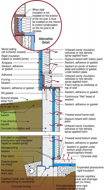
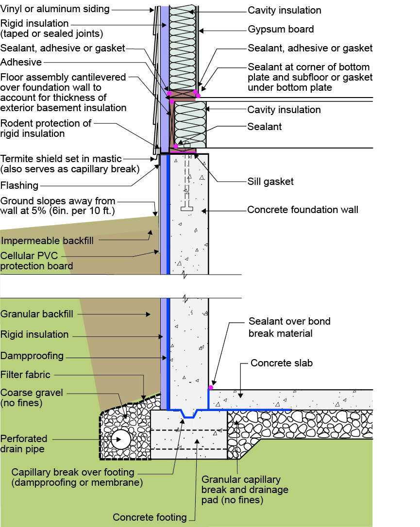
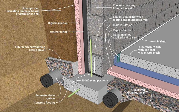
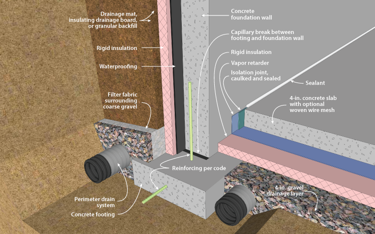
- Ensure the ground surface slopes away from the foundation. Ensure good vertical drainage along the foundation wall by backfilling with free-draining soil or installing geotextile drainage mat or dimpled plastic drain mat on the exterior of the foundation wall, and provide horizontal drainage with an exterior footing drain pipe. This is especially important in cold climates where there are concerns with frost heave.
See the Compliance Tab for links to related codes and standards and voluntary federal energy-efficiency program requirements.
Description
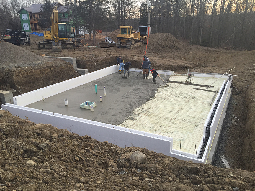
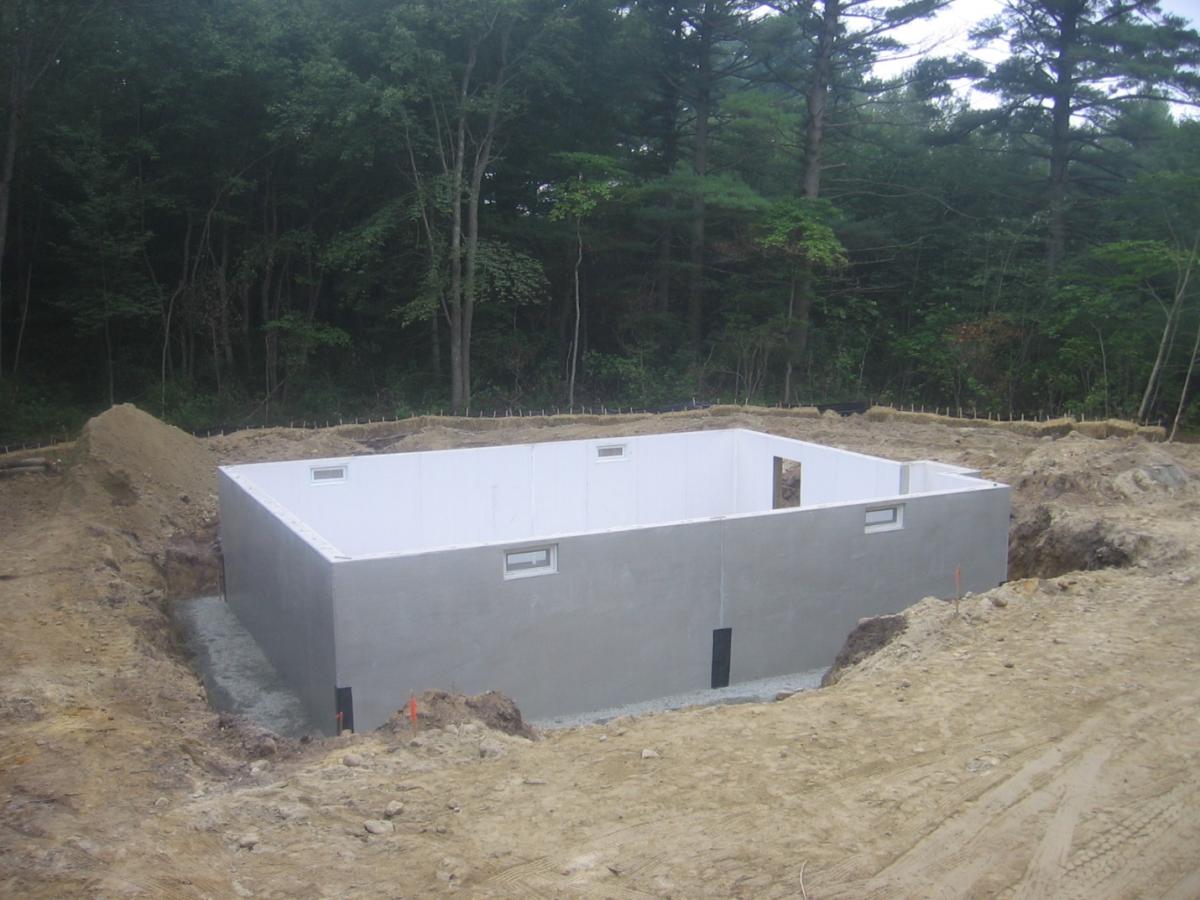
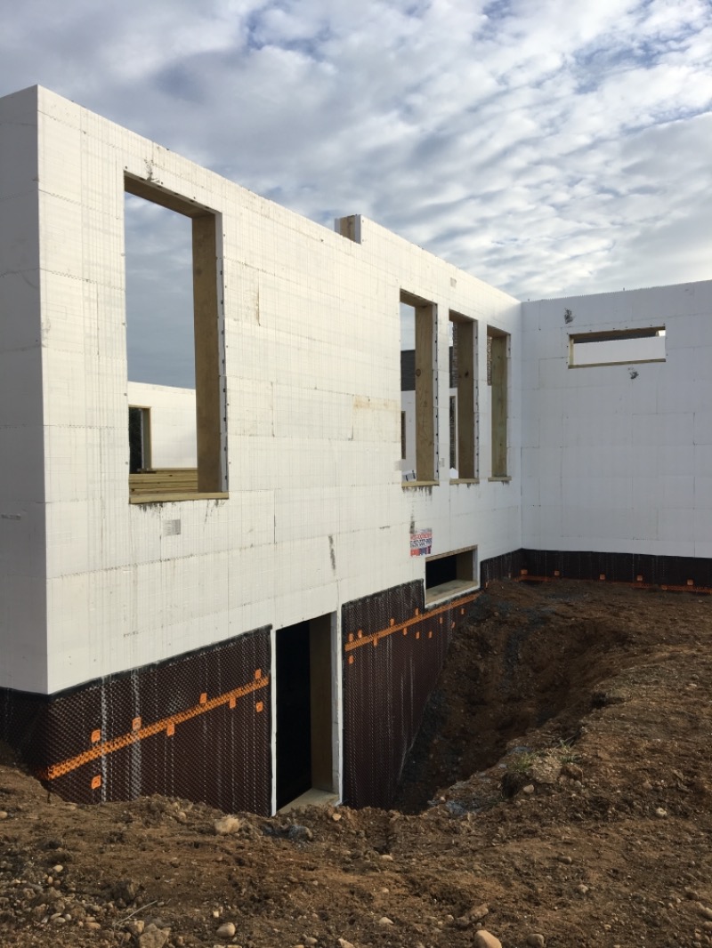
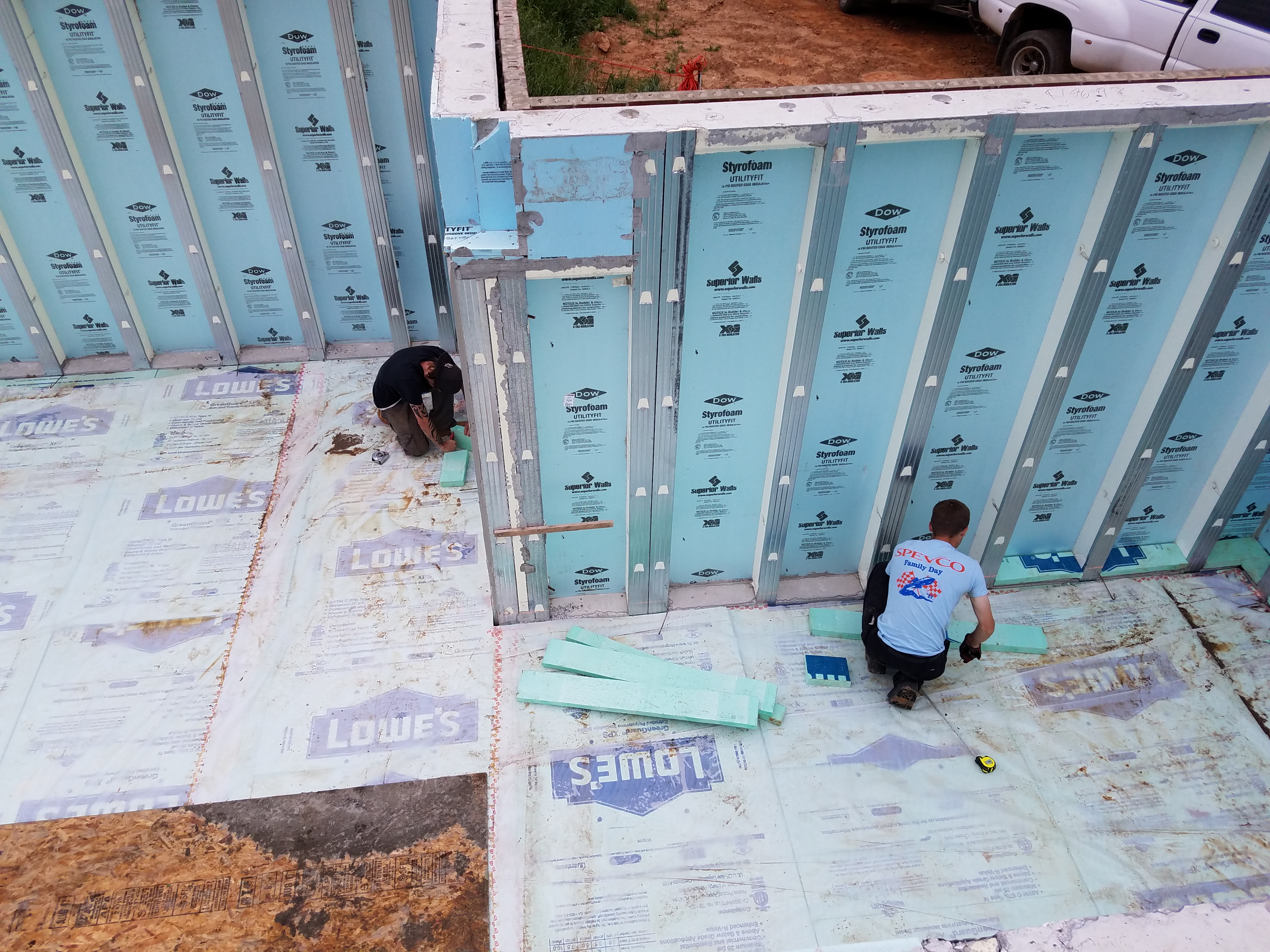
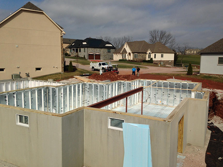
Because basements are largely below grade and winter ground temperatures are often warmer than winter air temperatures, the potential for heat loss from a basement is smaller than from the above-grade portions of a home’s envelope. While insulation levels below grade need not be as high as those of above-grade walls, insulating basements is critical to achieve the energy and comfort goals of high-performance homes. Figure 1 shows a basement insulated with insulated concrete forms (ICF), one of several options available for highly insulated basement walls.
Source
This guide describes good practices for insulating basements in new and existing homes. This is by no means an exhaustive list; rather, it is a short list of systems that can work well, can comply with current codes, and can be practically implemented by builders and contractors. For multifamily construction, consider also the Solution Center guide Air Sealing and Compartmentalization in Multifamily Buildings,
Before insulating a basement, be sure to assess (and address if necessary) key health, safety and durability issues. These include:
- Site/building drainage and water management
- Combustion safety
- Radon (See the EPA’s guide Building Radon Out: A Step-by-Step Guide on How to Build Radon-Resistant Homes, Also see Building Science Corporation’s information sheet on Soil Gas Control.
Insect and pest concerns (See the International Code Council’s (ICC's) guide, Pest Prevention by Design).
Where to Insulate
Foundation Walls or First Floor?
One of the first questions to answer when determining a basement insulation strategy iswhether to include the basement in the building envelope? If the basement will be part of the conditioned living space of the home, the insulation will be installed on the basement walls (either on the interior or exterior side of the walls). If the basement will not be part of the conditioned space than the insulation will be installed as part of the floor assembly of the first floor (usually between the floor joists).
Insulating at the Walls
In most cases insulating the basement walls and slab results in better overall thermal performance of the home rather than excluding the basement from the conditioned space of the home. Insulating the basement walls, rather than under the first floor, brings the basement within the thermal envelope or conditioned space of the home and connects the basement thermally to the rest of the house. This will keep the basement warmer during the winter. In the summer, a conditioned basement will usually be dryer than an unconditioned basement. A warmer, dryer basement can have much more value as a functional, usable space. It also provides better conditions for HVAC equipment.
In extremely cold climates, insulating the basement walls may be critical to keep basement temperatures above freezing. This is especially important if there is mechanical equipment or plumbing in the basement, e.g., a boiler, furnace, water heater, ducts, and/or piping, Connecting the basement to the conditioned space will reduce the cooling load during the summer months because the ground is generally cooler than the air within the home. It’s true that good basement wall insulation will limit this cooling effect, but even a home with a well-insulated basement will generally require less air conditioning energy than the same home with an unconditioned basement and insulation installed only beneath the first floor.
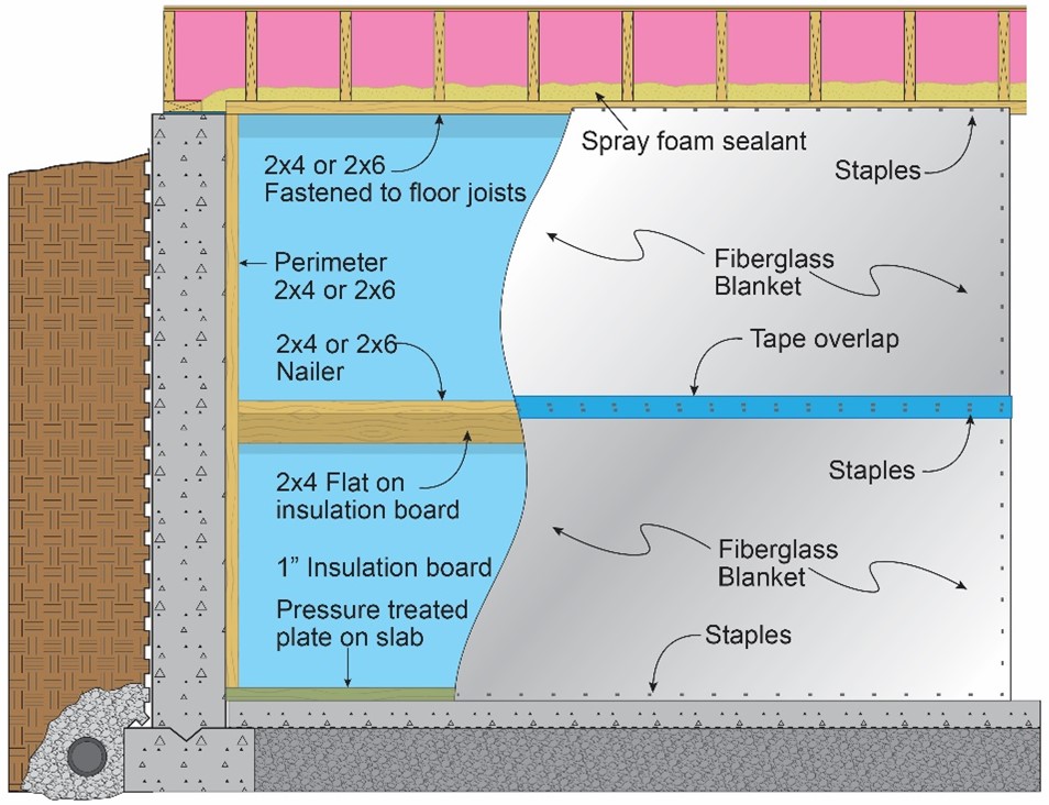
Insulating Under the First Floor
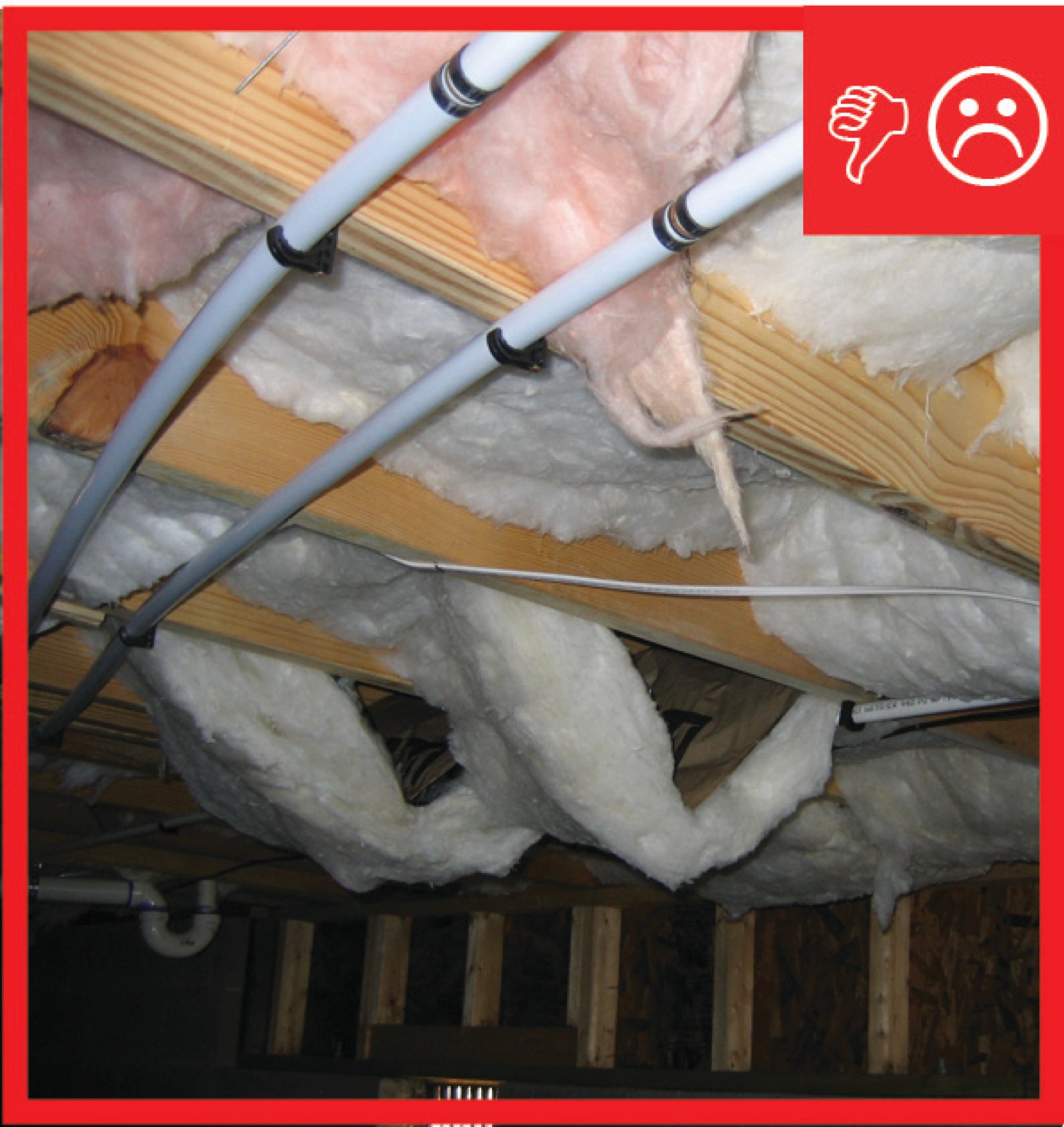
Insulating under the first floor, rather than along the walls will result in an uninsulated basement that is outside the home’s thermal envelope. While insulating only beneath the first floor may result in reduced performance compared to a fully- insulated basement, there are some scenarios where this strategy is chosen. Reasons could include:
- Water management. If moisture management strategies do not keep the basement consistently dry (e.g., if the area is prone to seasonal flooding), insulating at the first floor may be the best option to avoid repeated damage to water-susceptible materials.
- Combustion safety. It is strongly recommended that airtight buildings exclude natural-draft combustion appliances from the insulated enclosure. If natural-draft appliances are located in the basement and are not likely to be replaced with non-combustion or sealed-combustion direct-vent appliances in the near future, air-sealing and insulating at the first floor may be a safer option than air-sealing and insulating the basement walls and floor. For information on assessing combustion safety see these guides:
Cost. While insulating the basement walls generally results in better performance, this strategy is often more expensive, because more insulation will be needed to cover the walls and labor costs will be higher. Some choose to insulate at the floor for cost reasons, especially for retrofit projects.
Inside or Outside of Foundation Walls?
If the basement will be part of the conditioned area or living space of the home, the basement walls can be insulated along either the inside surface or the outside surface of the exterior walls. Insulating on the outside of a foundation wall is usually only a practical option in new construction due to the excavation costs associated with an exterior installation. Most retrofit strategies involve installing insulation on the inside of the foundation walls unless major excavation is already necessary for foundation repair or site water management.
In most cases, insulating on the outside can result in better moisture management of the foundation assembly, but there are challenges with protecting the insulation at and above grade. These challenges lead many designers and builders of new homes to choose interior basement insulation. Examples of both strategies—as well as challenges and limitations of each—are discussed below.
Systems Described
While there are many viable basement insulation strategies, common systems include:
- Exterior rigid insulation on concrete walls
- Insulated Concrete Forms (ICFs)
- Precast foundations
- Interior insulation:
- Foil-faced rigid foam left exposed
- Rigid foam covered with drywall
Spray foam covered with drywall.
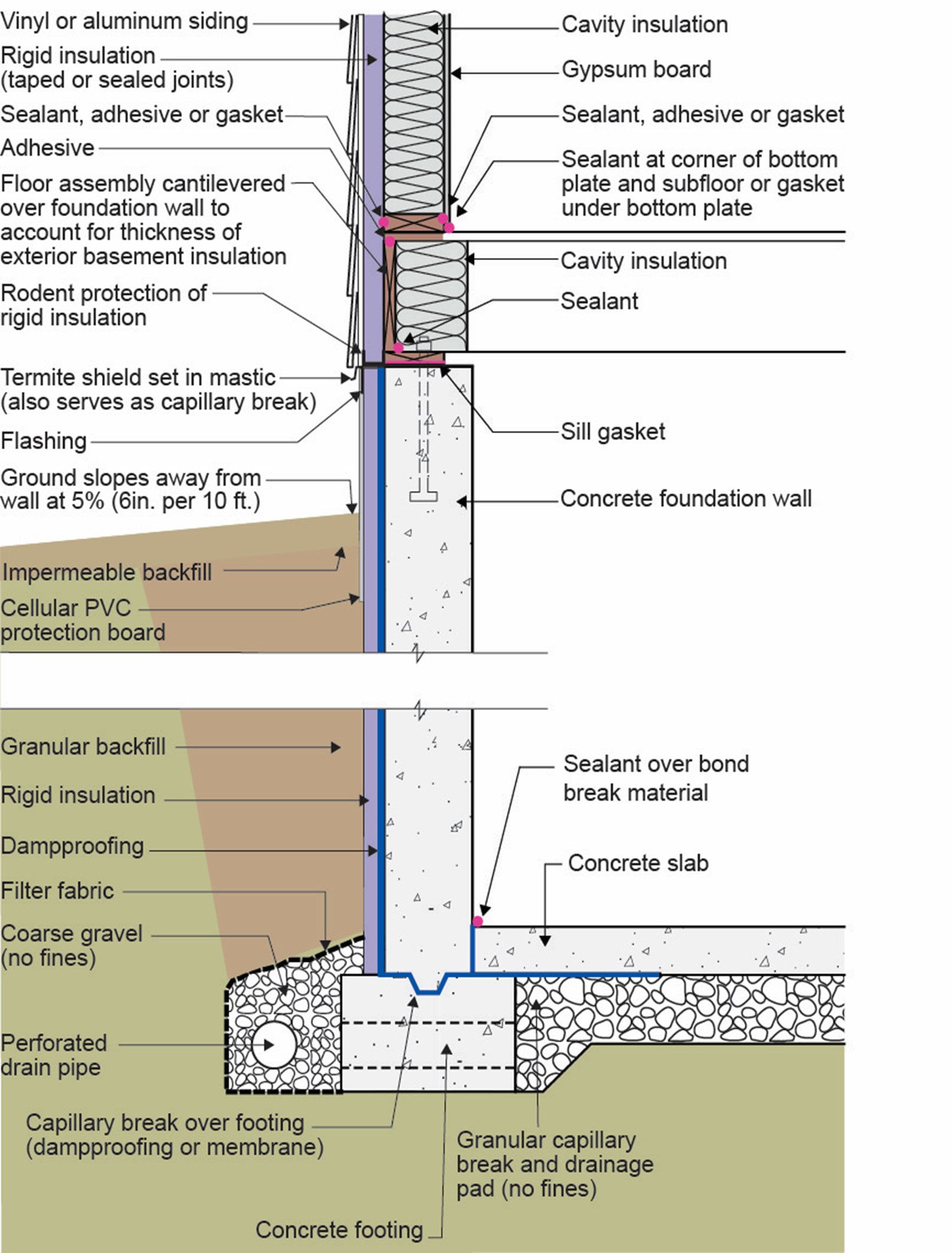
Exterior Rigid Insulation on Block or Poured Concrete Walls
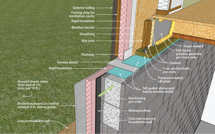
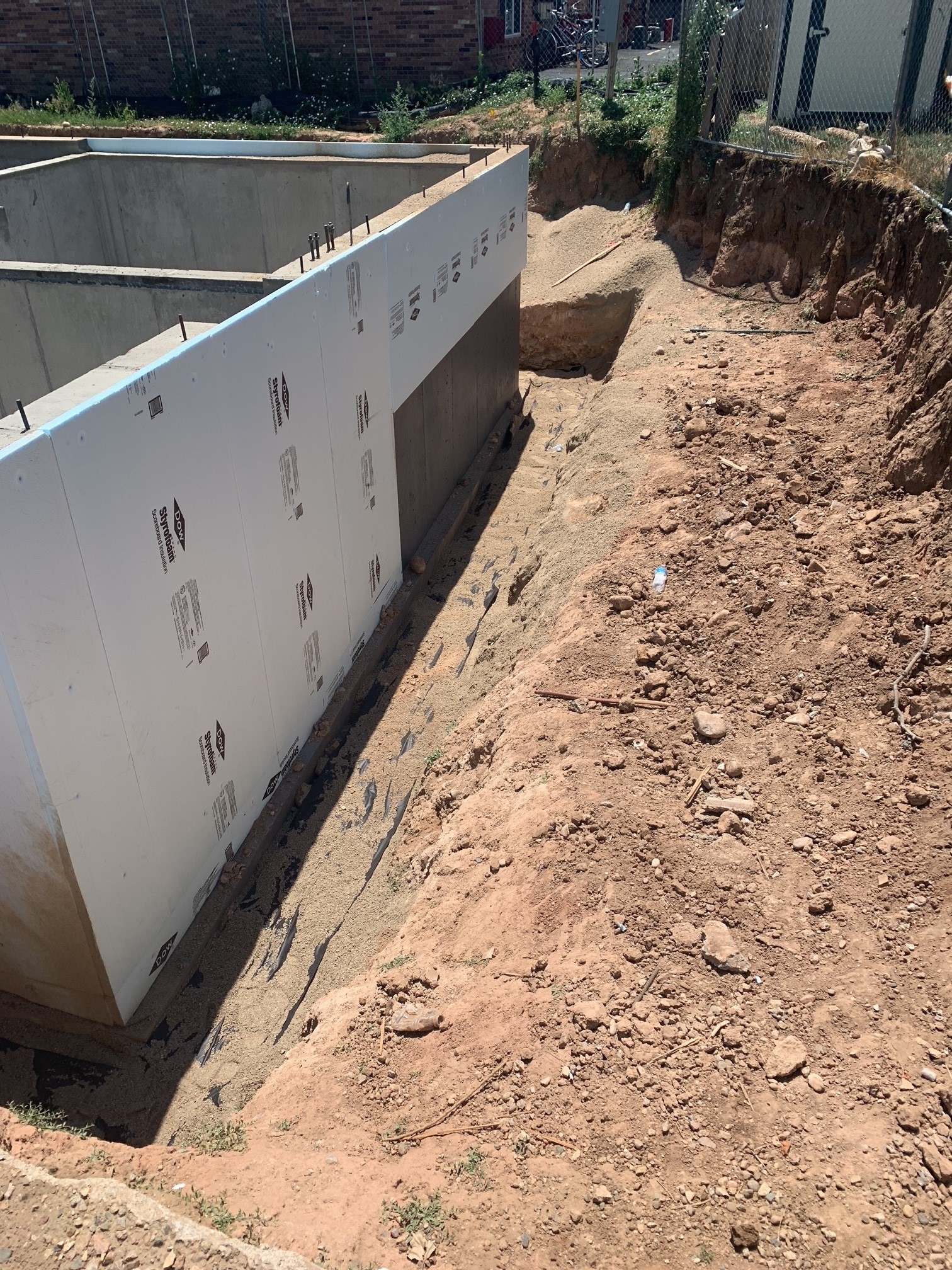
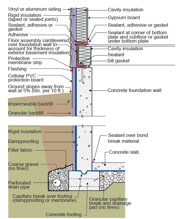
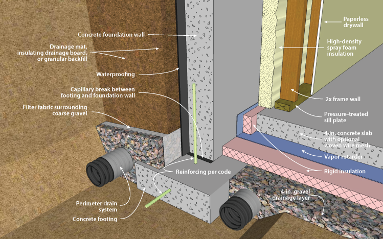
Rigid insulation board is attached to the exterior of the concrete from the base of the above-grade wall down to the footer. The board should be installed over a paint-on water proofing membrane. A dimpled plastic drainage sheet product can be installed over the membrane to provide hydrostatic pressure relief. The rigid insulation board can be installed in one or more layers (Figure 2), each one or more inches thick depending on the insulation level required for the climate zone. Seams should be taped and if more than one layer is installed the seams should be staggered to reduce the risk of water intrusion. Extruded polystyrene (XPS) foam, rigid fiberglass, and mineral wool boards are the most common materials for insulating the exterior of foundation walls. None of these materials retains water, so long-term thermal properties should not be significantly affected by moisture.
Source
Rigid fiberglass and mineral wool boards have a thermal resistance of approximately R-4 per inch (ft2hr°F/Btu-in). To achieve the same R-value as XPS insulation, the thickness of these insulations must be approximately 25% greater than XPS (which is R-5 per inch).
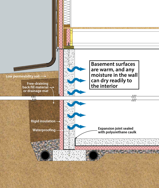
In most cases, insulation on the exterior of basement walls can result in drier foundation assemblies and basement conditions. Because of the difficulty of accessing the foundation exterior in existing buildings, exterior foundation insulation is usually only practical for new construction. Other key challenges for exterior insulation systems are:
- Protecting the insulation at and above grade
- Insect and pest management (see the Building America Solution Center guides Reduce Pest Intrusion, Pest-Resistant Ground Cover at Foundation Perimeter, and Screens and Other Deterrents for Birds, Rodents, and Other Pests for some mitigation ideas)
- Transitions between foundation insulation and above-grade walls
- Achieving higher R-values can be more difficult than with interior insulation (although a combination of both interior and exterior insulation is possible).
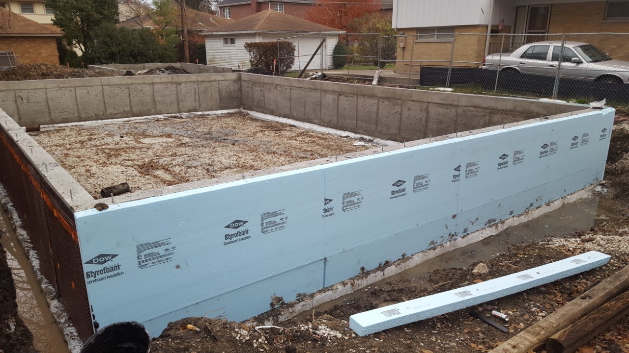
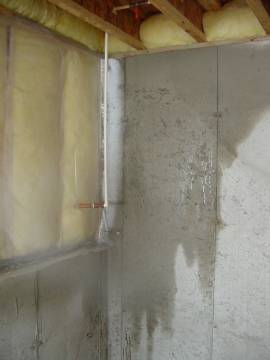
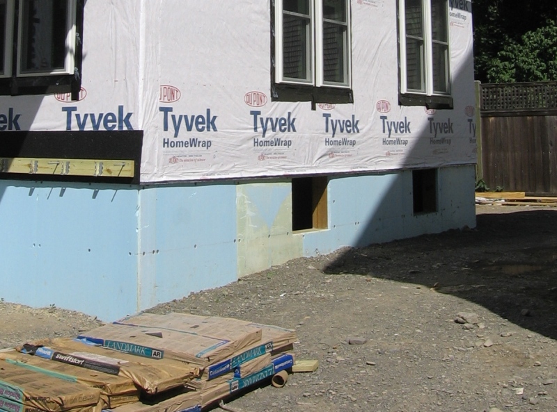
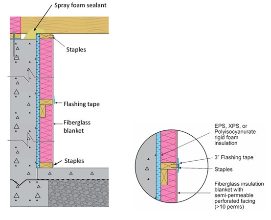
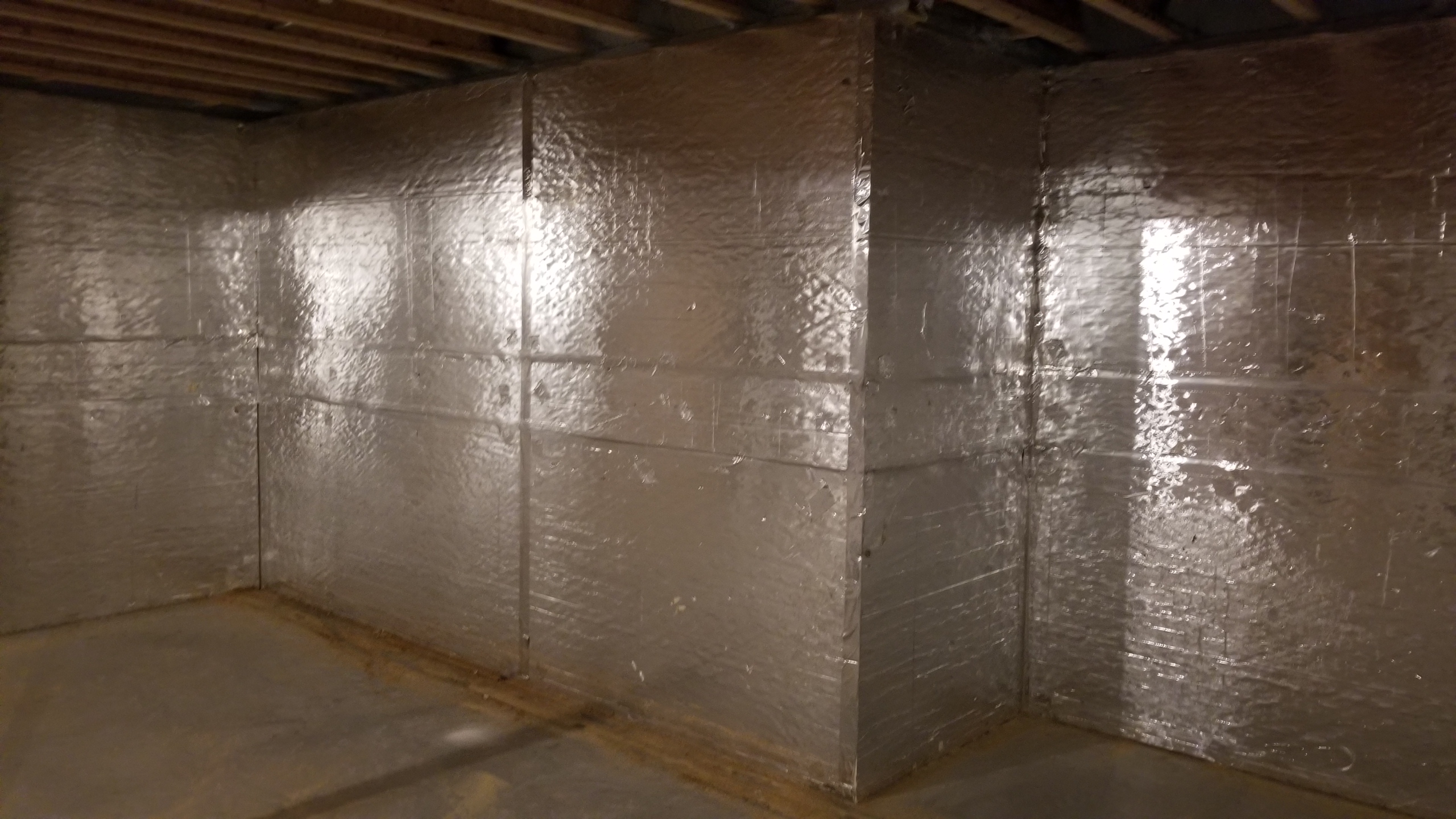
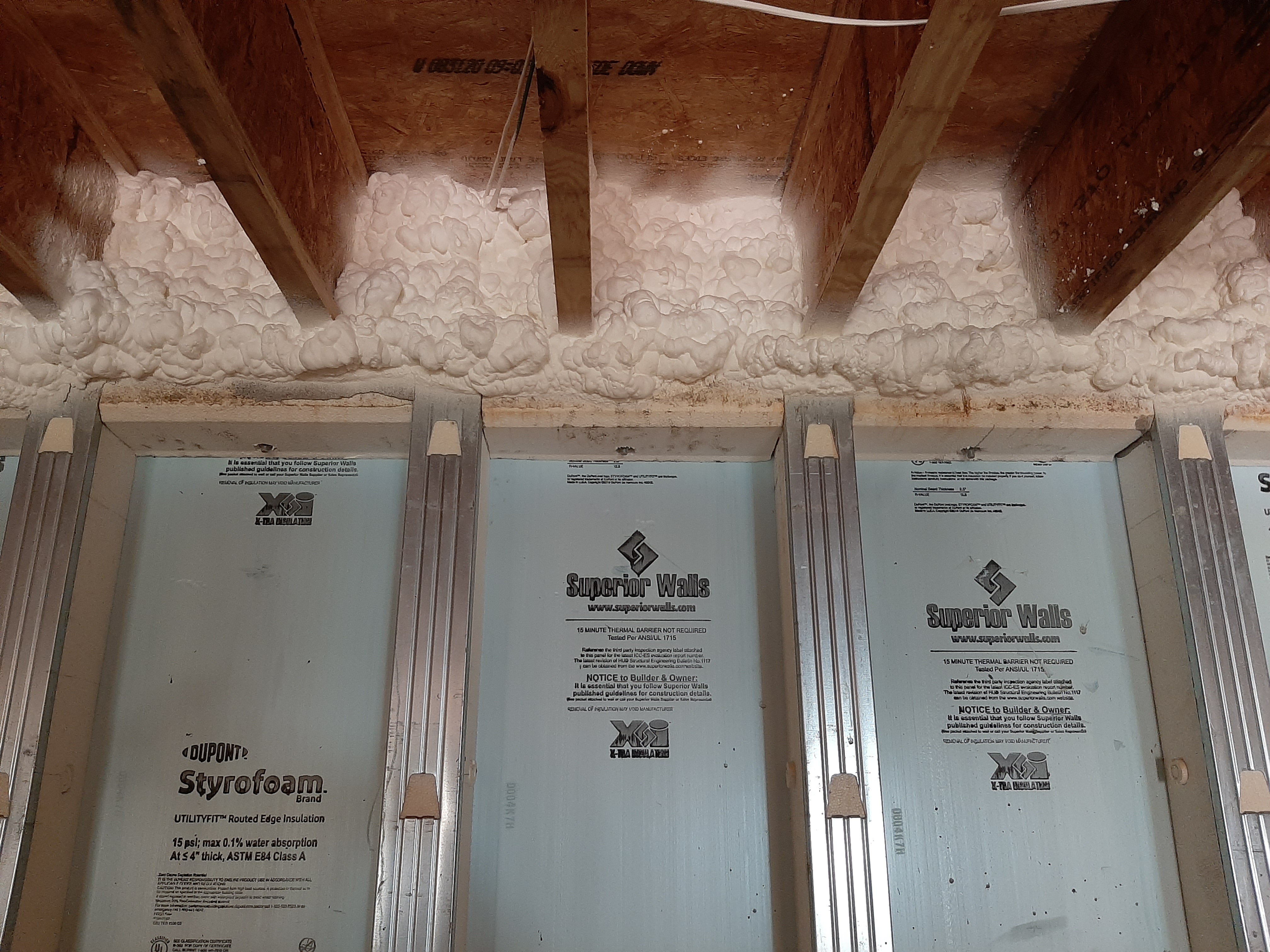
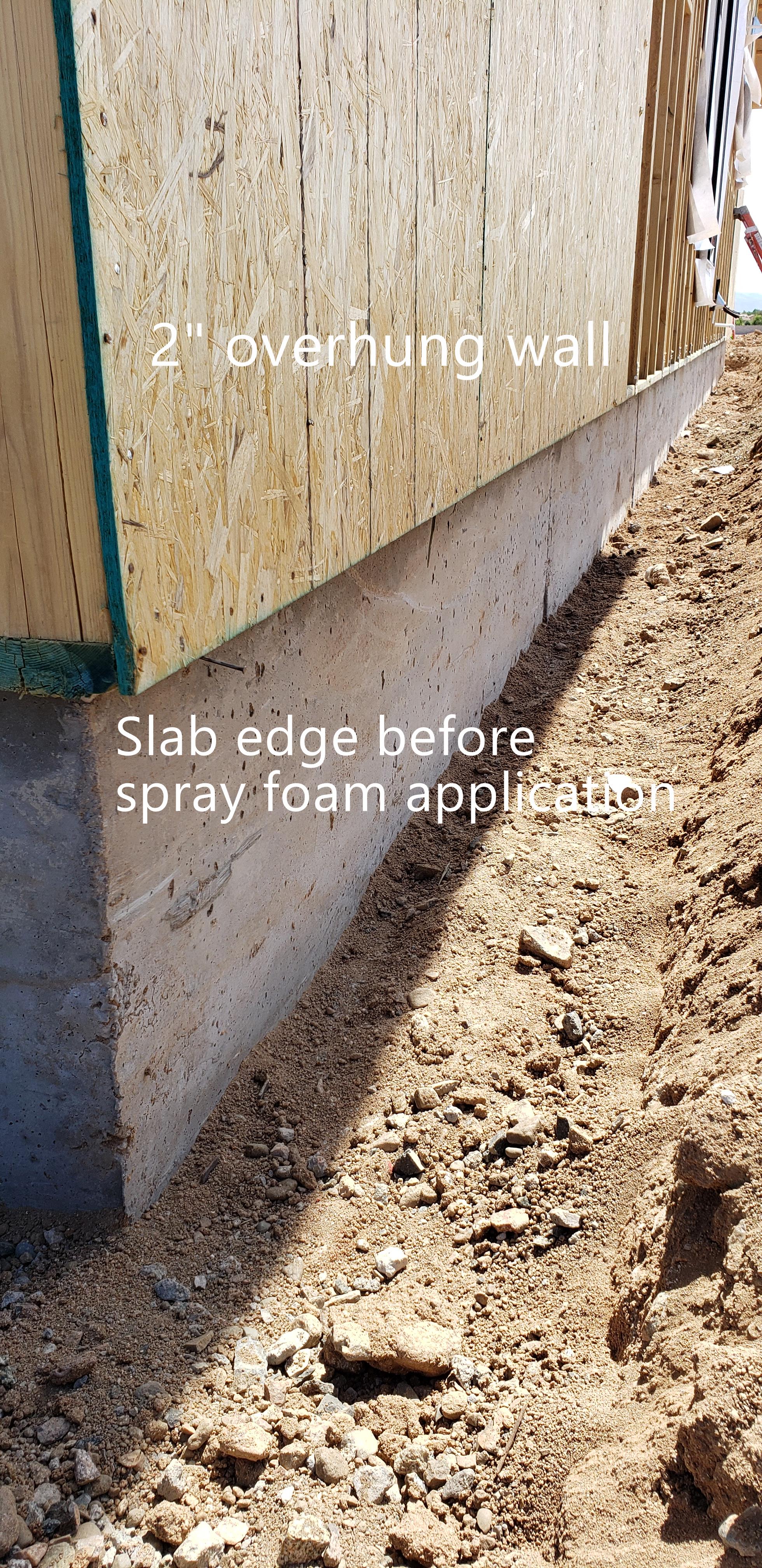
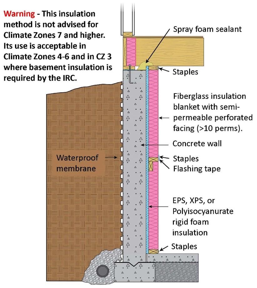
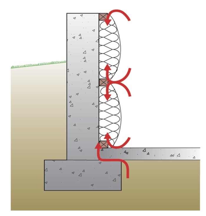
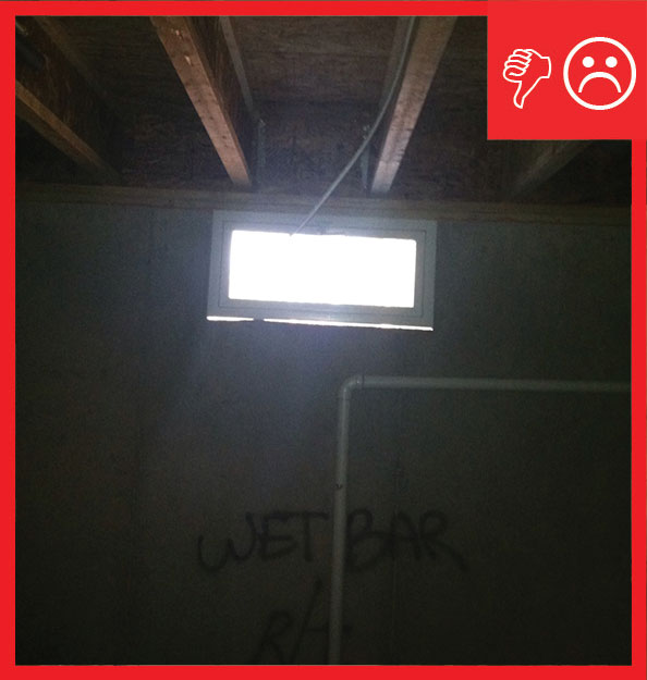
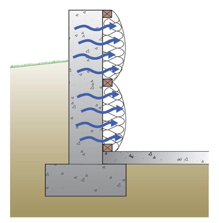
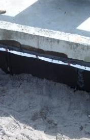
One common—though unacceptable—solution to protecting insulation at and above grade is simply to not insulate above-grade sections of the foundation wall (Figure 3). In this scenario, the un-insulated portion of the foundation wall (at grade and above) is exposed to the coldest temperatures. (Figure 4 shows an inside view of the wall shown in Figure 3; condensation and ice have formed on the inside surface of the wall.). Research has shown that insulating the top portion of the wall is by far the most critical for thermal performance; insulating only below-grade portions of the wall is ineffective in stopping heat transfer and leaves the thermal envelope incomplete.

Source
Document describing good practices for insulating basements in new and existing homes.
Source
Document describing good practices for insulating basements in new and existing homes.
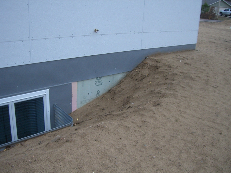
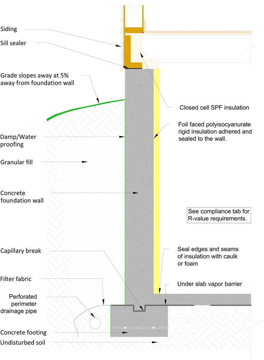
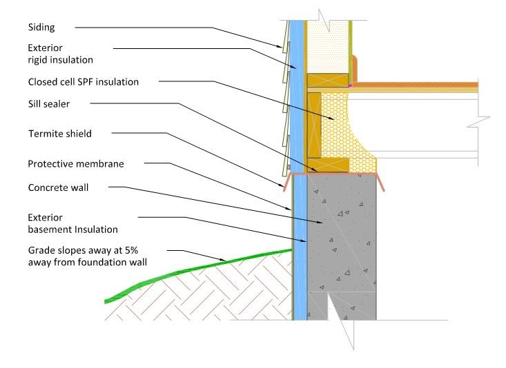
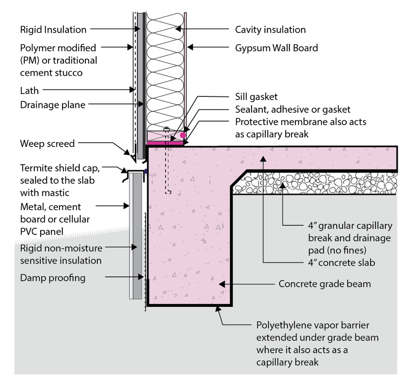
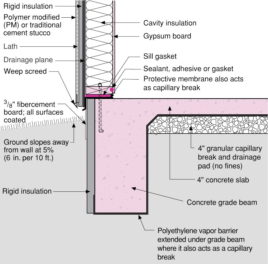
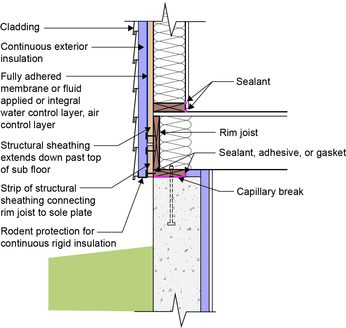
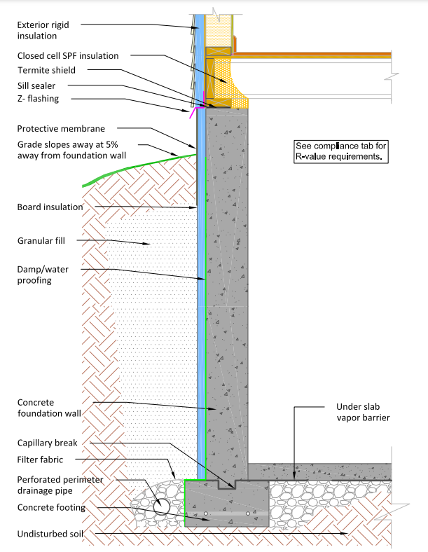
Insulation must be extended to the top of the foundation wall to provide a seamless thermal barrier in conjunction with the above-grade walls (Figure 5). This above-ground insulation must be protected with a durable material that can withstand environmental wear including weather, sunlight, pests, and physical impacts (Figure 6). Protective materials can include stucco, fiber-cement boards, fiberglass panels, vinyl sheets, aluminum coil stock, or even pressure-treated plywood. (For more options see this article, How to Finish Exterior Foundation Insulation).
Source
Document describing good practices for insulating basements in new and existing homes.
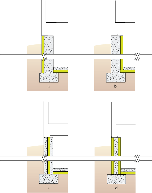
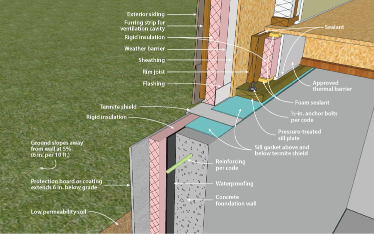
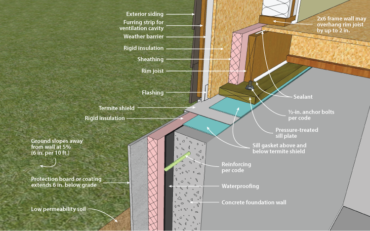
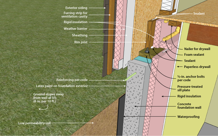
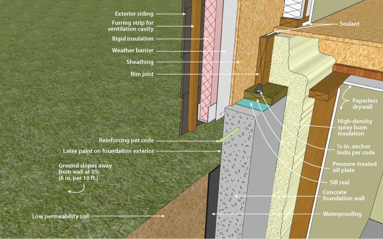
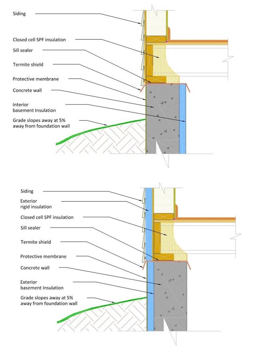
Another potentially tricky detail is integrating the extra dimension of the foundation insulation into the above-grade walls. Two possible solutions are presented here. In Figure 7, above-grade walls also incorporate rigid exterior insulation. In this case, there is usually little difference between the two planes. However, if the above-grade walls do not have exterior insulation, there must be a curb, flashing, or transition that protects the insulation, manages drainage well, and is aesthetically acceptable. One possible solution is presented in Figure 6.
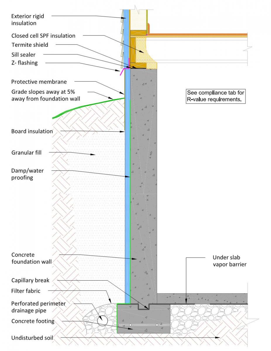

Source
Document describing good practices for insulating basements in new and existing homes.
When considering external foundation insulation strategies, it is critical to consider insects and pest management. While termites and other pests do not eat foam, they can easily tunnel through foam to reach wooden building components. Many insect management strategies incorporate a “vision strip,” typically a 3-inch gap in the insulation extending across the top of the foundation wall that exposes the concrete, so termite activity is visible. Another strategy is a termite “shield,” typically a piece of metal flashing that extends from the sill or insulation transition over the top of the foundation wall. These strategies do not necessarily stop termites, but the devices will force bugs out of the insulation where their presence can be noticed. See more information in the “Insect and Pest Management” section in the Success tab.
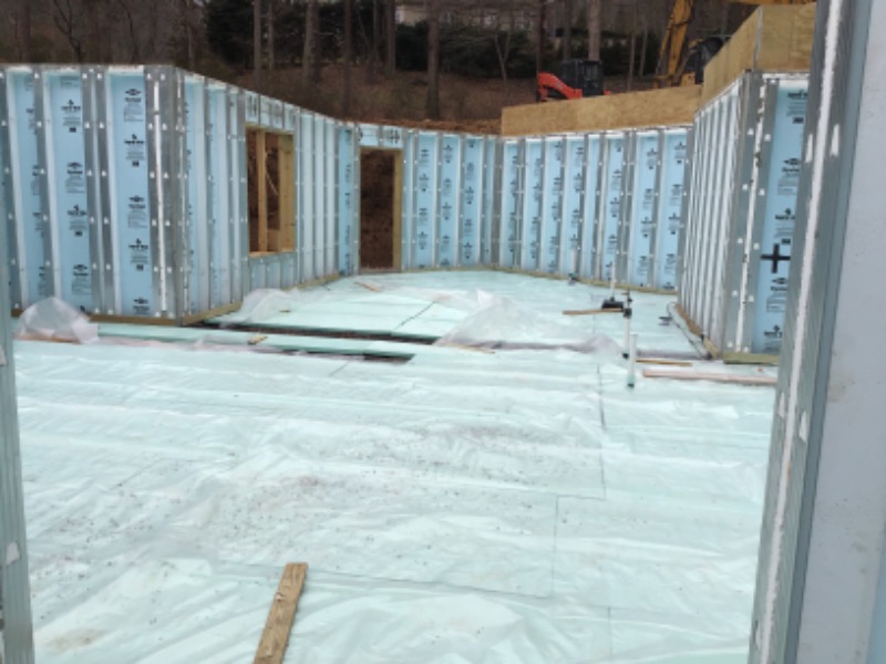
Insulated Concrete Forms (ICFs)
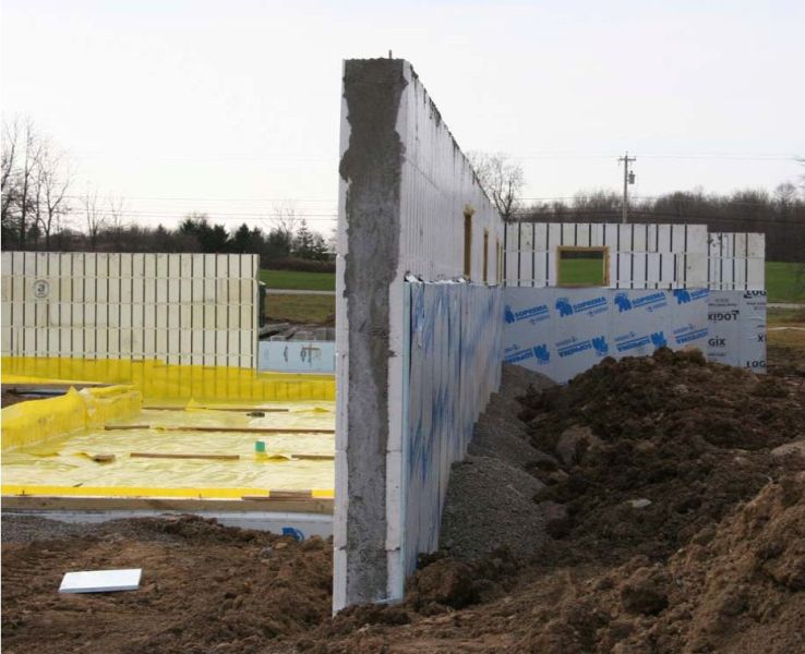
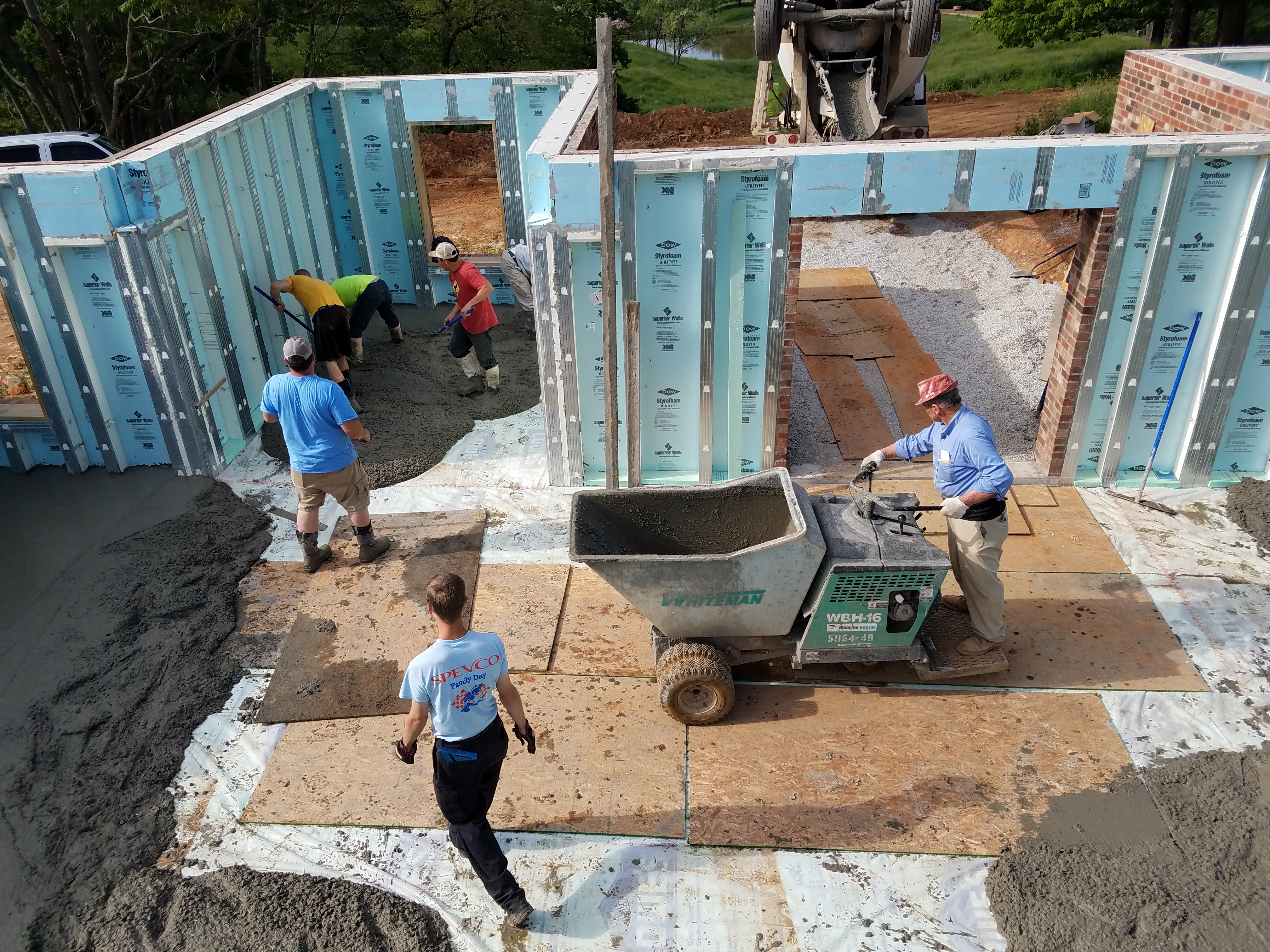
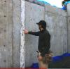
When making poured concrete foundation walls, builders typically use wood or metal forms to hold the concrete in place until it hardens. Another option is to use insulated concrete forms (ICFs) where the forms consist of hollow rigid foam blocks that stay in place after the concrete is poured to form a lasting layer of insulation on the inside and outside surface of the concrete wall. The rigid polystyrene foam (either EPS or XPS) is connected by polymer spacers to form large (e.g., 9”x18”) hollow blocks that are stacked in courses to form a hollow wall (Figure 8). The wall is reinforced with steel rebar that is run horizontally and vertically through the spacers then the hollow space is filled with concrete (Figure 8). Many ICF systems include vertical plastic or metal nailing strips to which interior and exterior finishings can be attached. See the guide Insulated Concrete Forms for more information.
Instead of “sandwiching” concrete between the foam layers, another system sandwiches the rigid foam insulation between two layers of concrete. This approach can solve concerns about thermal barriers, some moisture issues, and possibly pest management concerns.
PreCast Foundation Walls
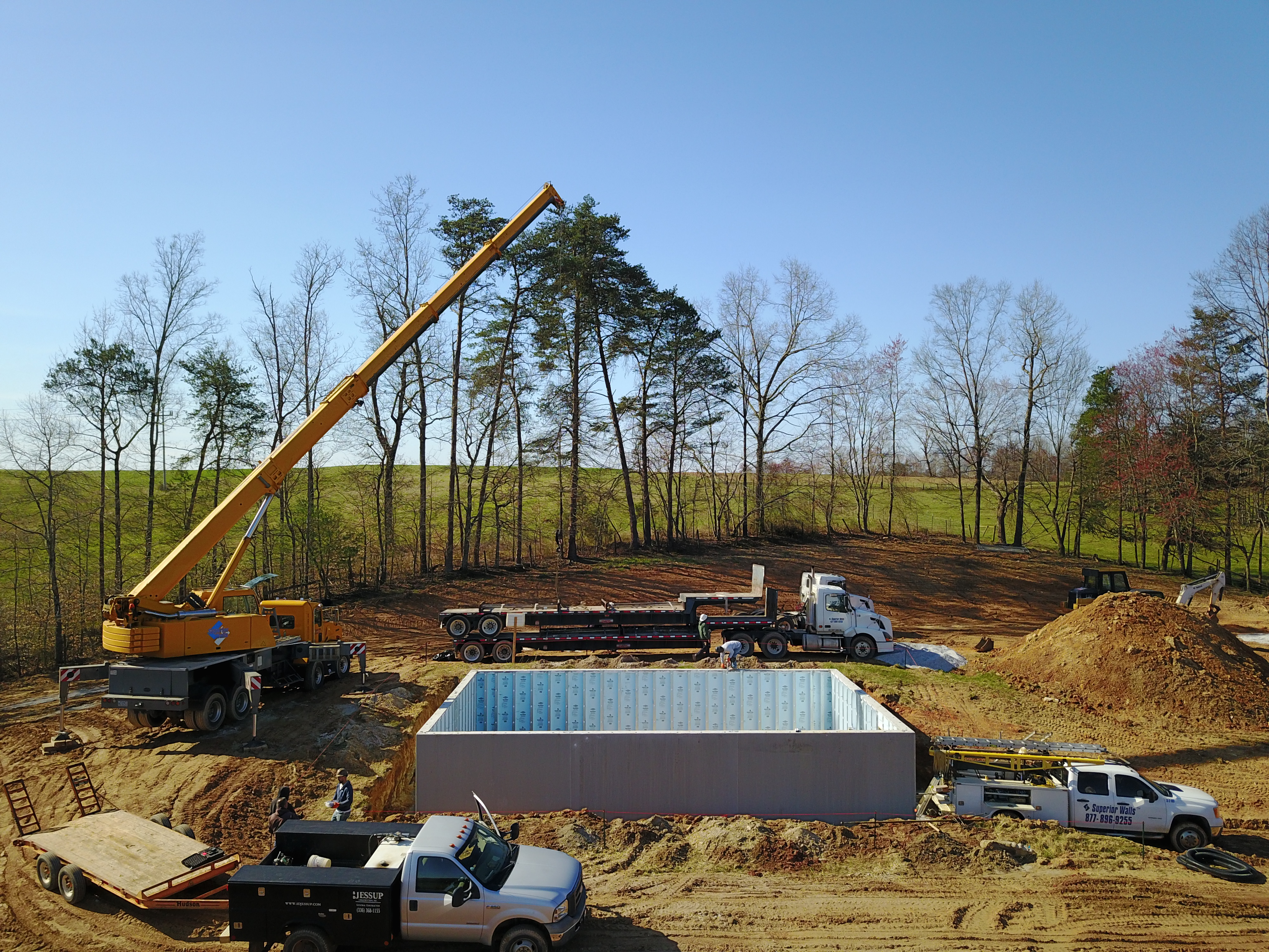
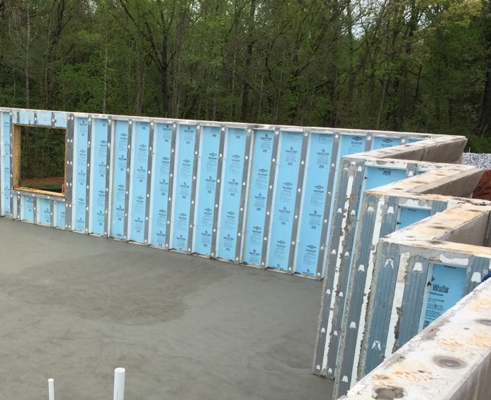
Precast concrete foundations have a significant presence in several regional markets, in particular in the Northeast and Midwest. Both of these regions are dominated by full basement foundations in residential construction, and both regions have robust pre-cast concrete industries. Precast foundations are factory-produced concrete panels designed for a specific project, shipped to the job site, and set up with a crane. Some panels consist of a layer of rigid insulation sandwiched between two layers of concrete. Other products use a thinner concrete shell with molded concrete ribs every 16 or 24 inches. The panels are monolithically poured with top bond-beams, bottom footers, and the evenly spaced concrete ribs. These thin-shelled rib systems can come from the factory with a layer of rigid insulation adhered to the interior side of the shell and wrapped around the ribs. The ribs are usually faced with sheet metal which is placed over the rigid foam to serve as a nailing surface for the ribs, which act like walls studs. The cavities between the ribs can be filled with additional blown or batt insulation.
Pre-cast panels are typically set on a compacted crushed stone base with no additional footing needed (Figure 10). The crushed stone base is placed and compacted uniformly over the entire foundation area (including under the slab). The first panel is meticulously located to pre-surveyed points, and the remaining panels are positioned in reference to it. Joints between panels are typically treated with two large beads of poly-butyl caulk with come-along bolt connections used to draw the panels together, then the below-grade surface is treated with one of a variety of damp-proofing or moisture-proofing techniques.
Pre-cast foundations can be set in a single day. Panel bracing is critical prior to backfilling, so the floor deck will have to be installed with limited at-grade access. The time savings are also labor savings, but material costs for pre-cast foundations are generally higher. Total installed costs are similar to those of poured concrete foundations (especially near precast plants) and are dependent on local market conditions.
Insulation on Interior of Foundation Walls
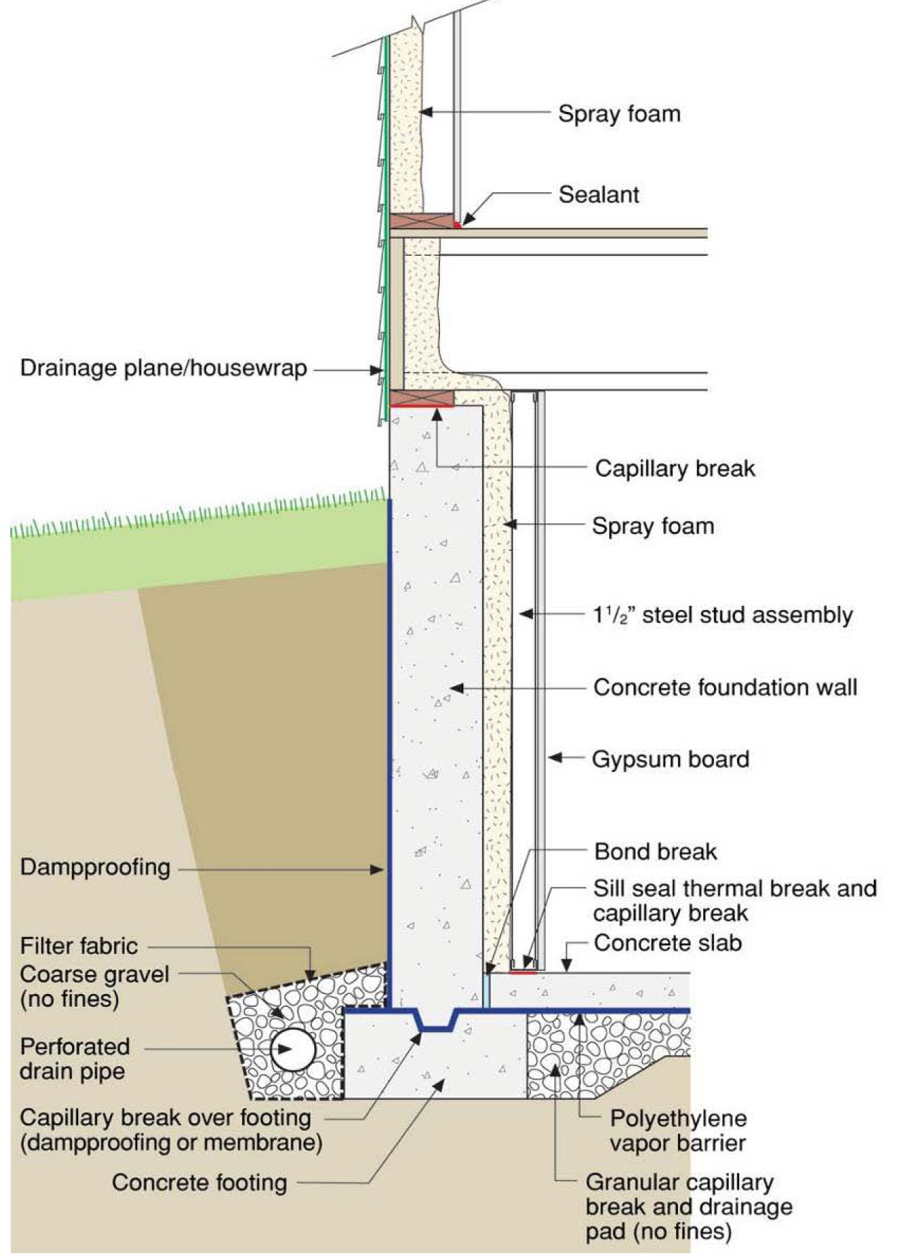
Interior basement insulation is often the only practical option in existing homes. Even in new construction, challenges with protecting insulation at and above grade and with integrating the extra dimensions of exterior insulation may lead some builders to install interior insulation. Building America researchers have found that the best interior basement wall insulation strategies have several key features:
- Non-fibrous insulation is installed directly in contact with the basement wall and there is no channel for air movement between the insulation and the concrete
- The assembly is air sealed so that basement air (and the moisture in it) cannot move into the insulation assembly
No moisture-sensitive materials are in contact with the concrete walls or floor (this is often addressed by building codes).
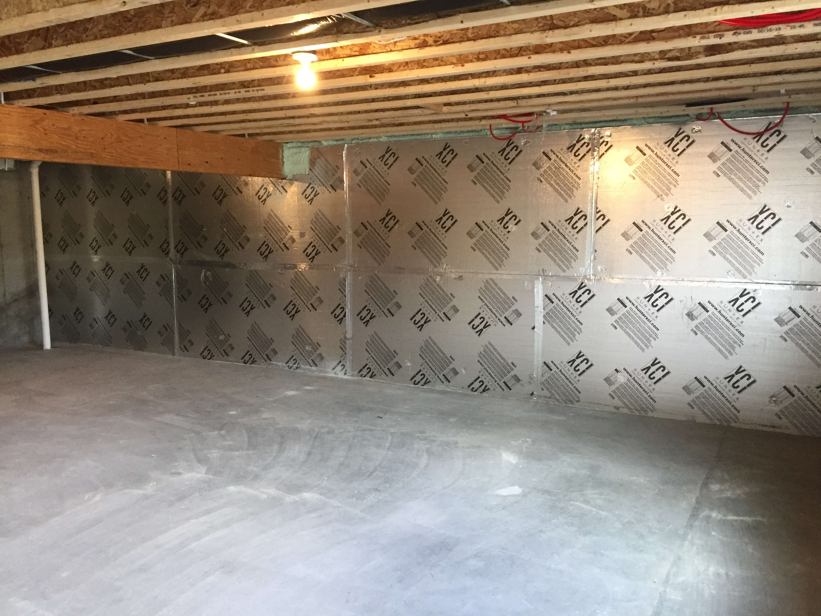
Exposed, Foil-Faced, Polyisocyanurate Board
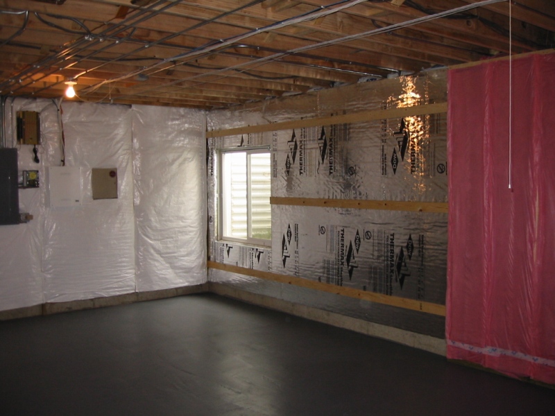
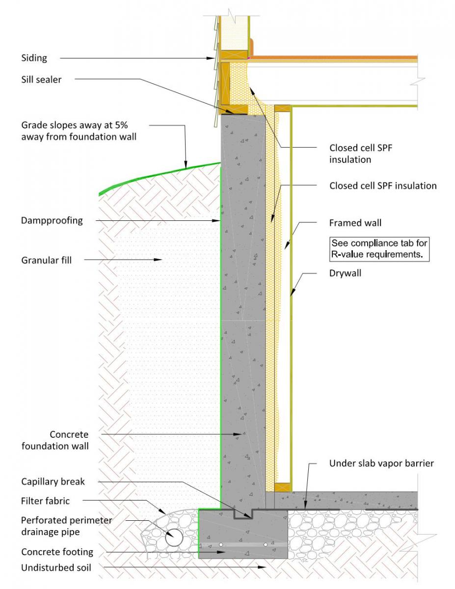
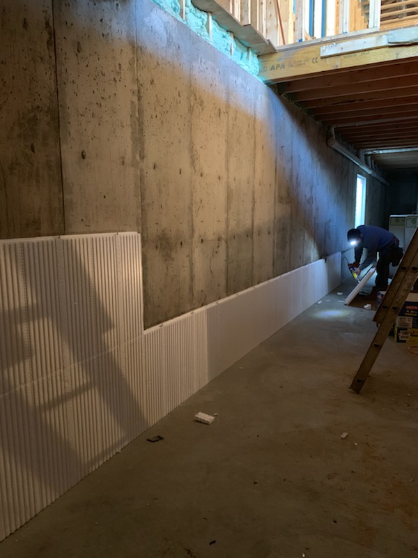
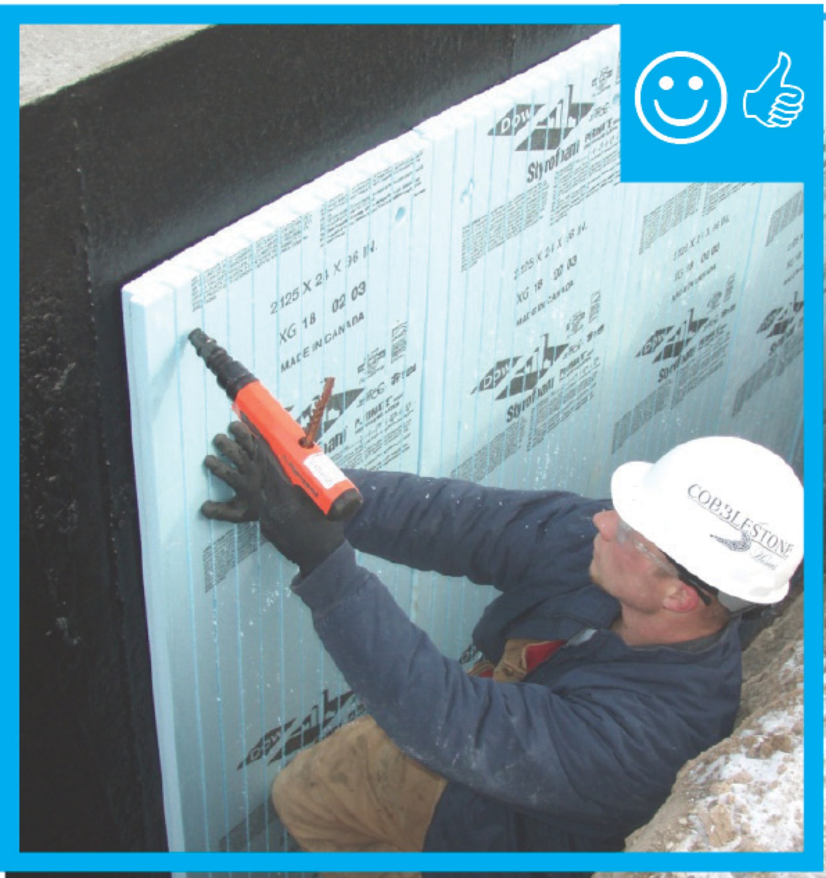
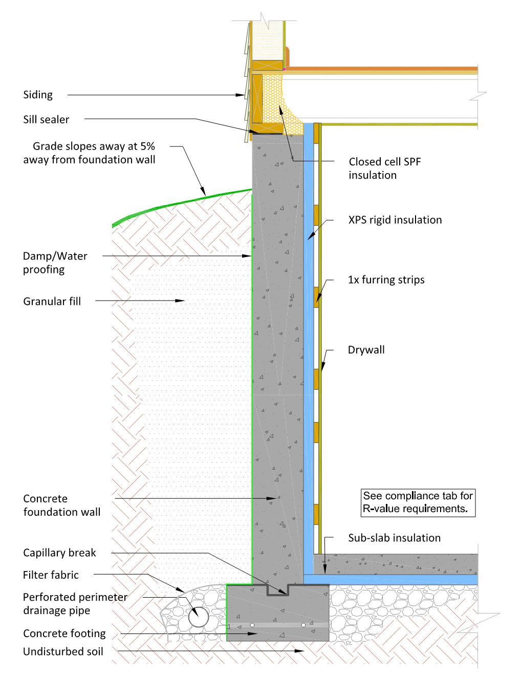
Polyisocyanurate has an R-value of approximately R-6 per inch (ft2hr°F/Btu-in), although typically one inch is installed to meet R-5 requirements, two inches are installed to reach R-10, and three inches are installed to reach R-15. The rigid polyiso boards may be fastened to the concrete with either construction adhesive or with mechanical fasteners. Figure 11 shows insulation attached using 1x strapping as a base for the fasteners. The polyiso boards should be completely sealed to each other and to the concrete wall (Figure 12). There should be no avenue for air movement between the foam and the foundation wall. Insulation seams can be sealed with caulk, foam, foil tape, or polypropylene tape. Caulk or foam should be used at the edges of the insulation (near the sill, the slab, around windows or doors, etc.).
The International Residential Code requires foam insulation to be covered with a thermal barrier for fire resistance (2015, 2021 IRC, Section R316.4). The most common type of barrier is drywall. Attaching drywall over foam can be costly; however, it is often already factored into project costs if the basement will be finished for living space. At least one manufacturer of foil-faced polyisocyanurate board insulation has a product that is allowed to remain exposed if installed in a space not typically used as living space, per an International Code Council (ICC) Evaluation Services report (ICC 2006, NER-681). In many jurisdictions, this product can be left exposed against basement walls without drywall or an additional thermal barrier.
As with most systems described here, spray foam can be a good option to seal and insulate the sill and band joist areas. Many codes allow for this small area of foam to be left exposed in these locations (2015 IRC, Section R316.5.11).
Polystyrene Board with Drywall
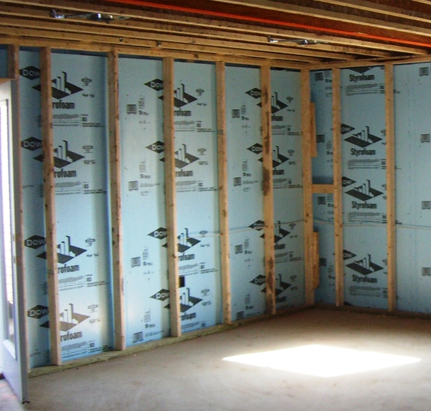
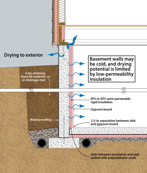
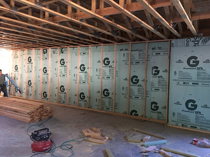
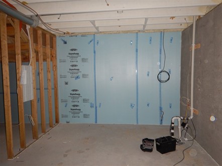
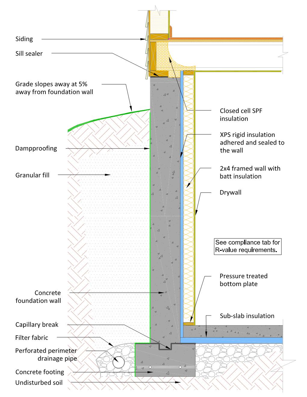
Both unfaced expanded polystyrene (EPS) and extruded polystyrene (XPS) rigid foam are common basement insulation materials, but they cannot be left exposed without a thermal barrier for fire protection (2015, 2021 IRC Section R316.4). The most common such barrier is ½-in. drywall.
Of these two foams (EPS and XPS), XPS is more commonly used because it has a higher R-value (R-5 per in. rather than R-4). One commonly cited drawback of XPS is that its blowing agent is a potent greenhouse gas, although product options with lower global warming potential are now available. As with the polyisocyanurate foam insulation systems, XPS foam can be attached to the wall with construction adhesive or with mechanical fasteners. Seams in the foam should be sealed, and the top and bottom edges should be sealed to the concrete with caulk or foam. In one method of mechanical attachment, fasteners are attached through 1x furring strips, which serve as a base for attaching drywall with screws. Using these furring strips against irregular walls can be more challenging, as concrete surfaces are not always smooth and the drywall may follow any irregularities in the furring or wall shape. While electrical wires can be run in the gap between the drywall and the foam, electrical boxes (when installed) must be recessed into the foam. The foam edges around these penetrations should also be air-sealed with caulk, foam, or tape.
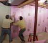
Some builders choose to install a conventional framed wall to the inside of the rigid foam (Figure 13) to avoid wall irregularity. These framing cavities can be filled with batts or other appropriate cavity insulation. With the addition of a framed wall with cavity insulation, less rigid foam may be needed to meet target R-values.
Spray Foam with Framing and Drywall
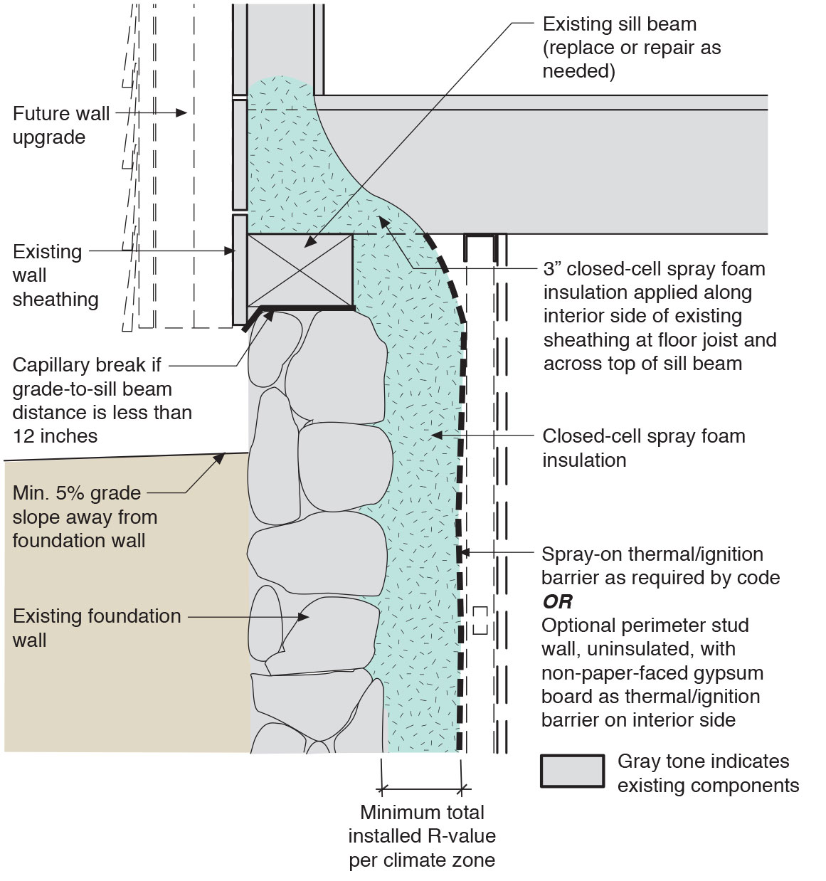
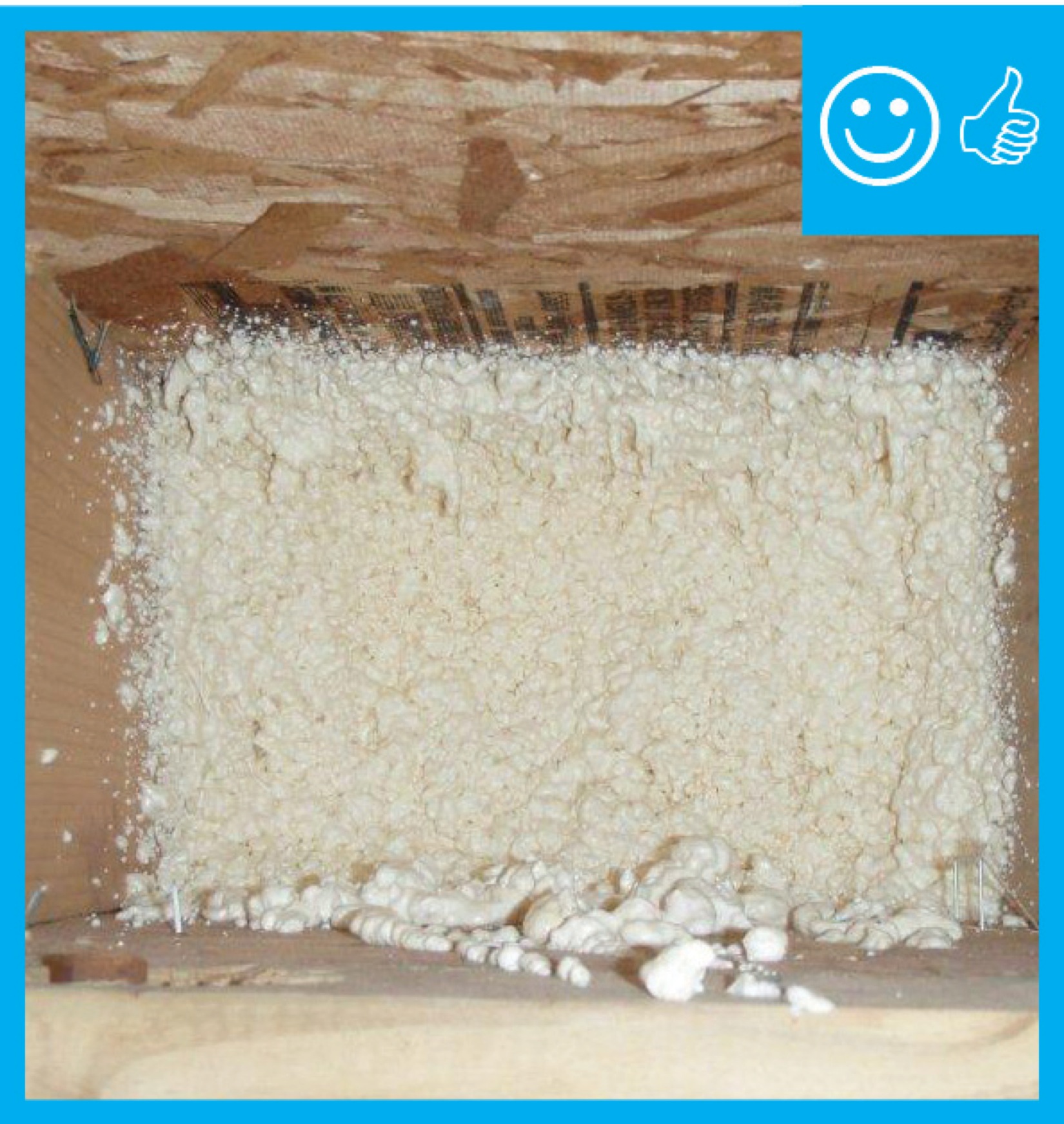
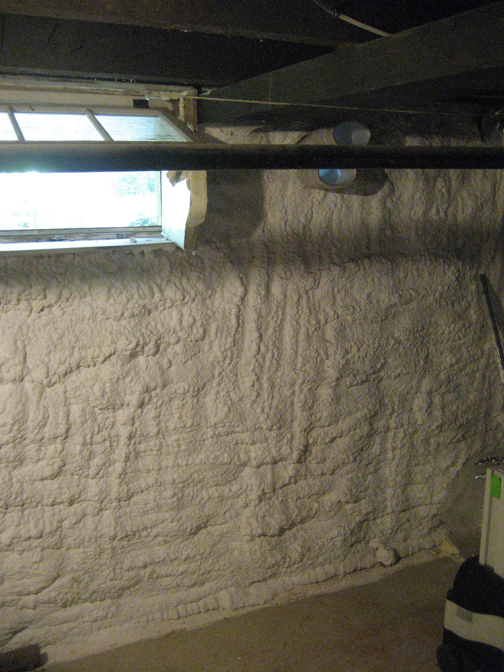
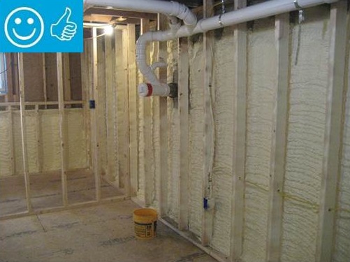
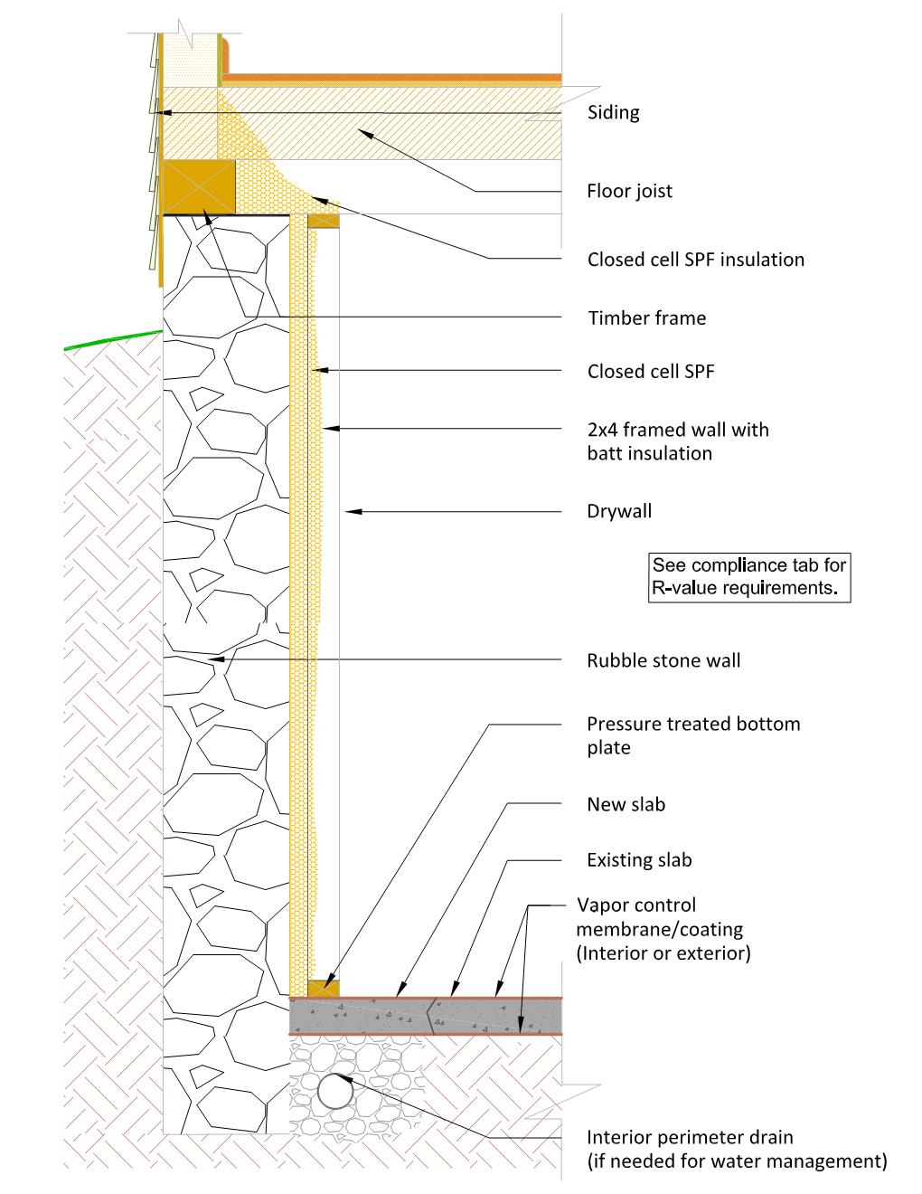
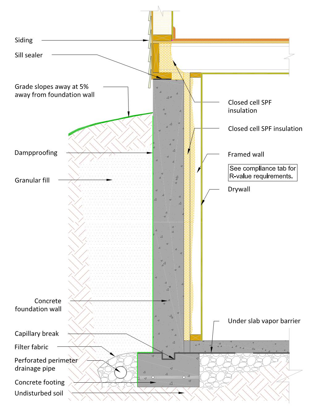
Sprayed polyurethane foam can provide excellent air sealing and thermal resistance in many envelope systems. The chief drawback to the product is cost, as it is usually more expensive to install than rigid foam boards. Like unfaced foam boards, spray foam must be covered with a thermal barrier. While spray foam can be effective in many types of foundation walls, it is especially excellent for improving the thermal and moisture performance of irregular walls (such as stone foundations). As open-cell spray foam can absorb and retain water (up to 40% of its volume), closed-cell foam is recommended for most foundation wall applications.
A recommended spray-foam system for a poured-concrete or block wall is shown in Figure 14. Framing is installed at least one or two inches away from the interior surface of the foundation wall to allow space for a continuous layer of spray foam to be blown in behind the framing. Drywall is attached to the 2x4 framing and provides the thermal barrier. As with the XPS system discussed above, it’s possible to use a hybrid system with spray foam directly against the foundation wall and cavity insulation within the framing. It may also be practical to use 2x3 framing or steel framing in some applications.
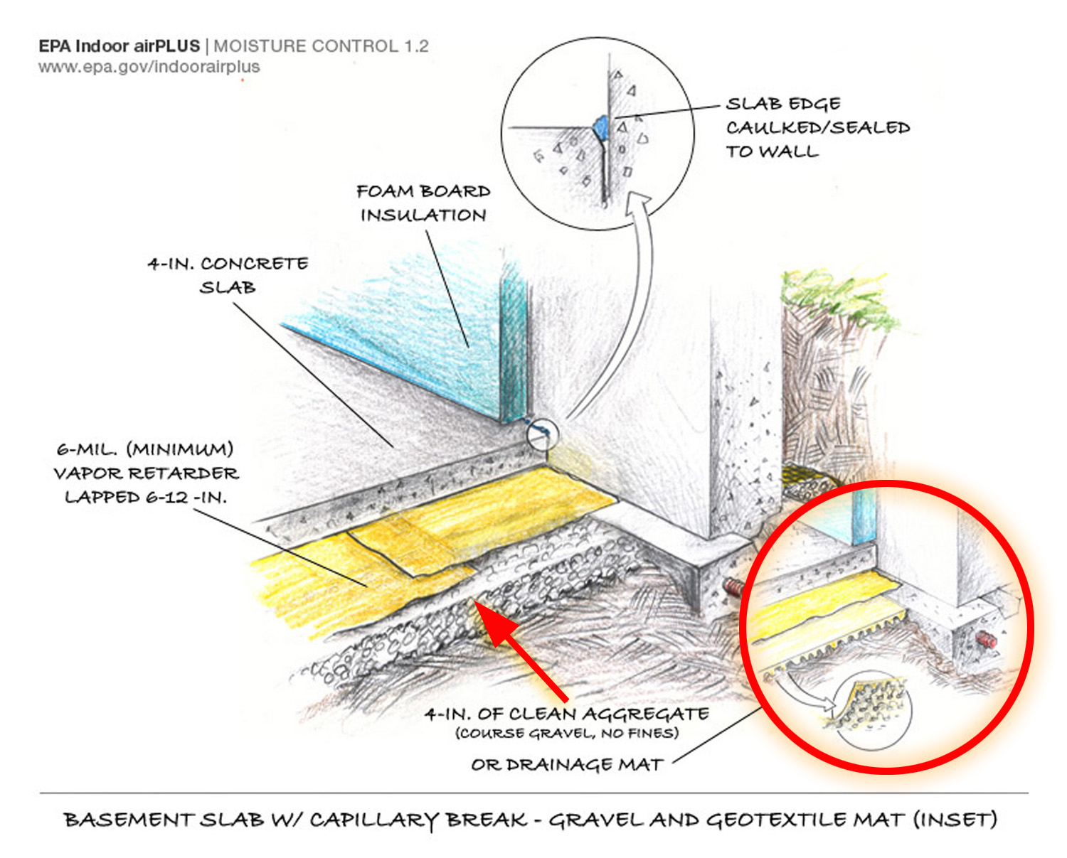
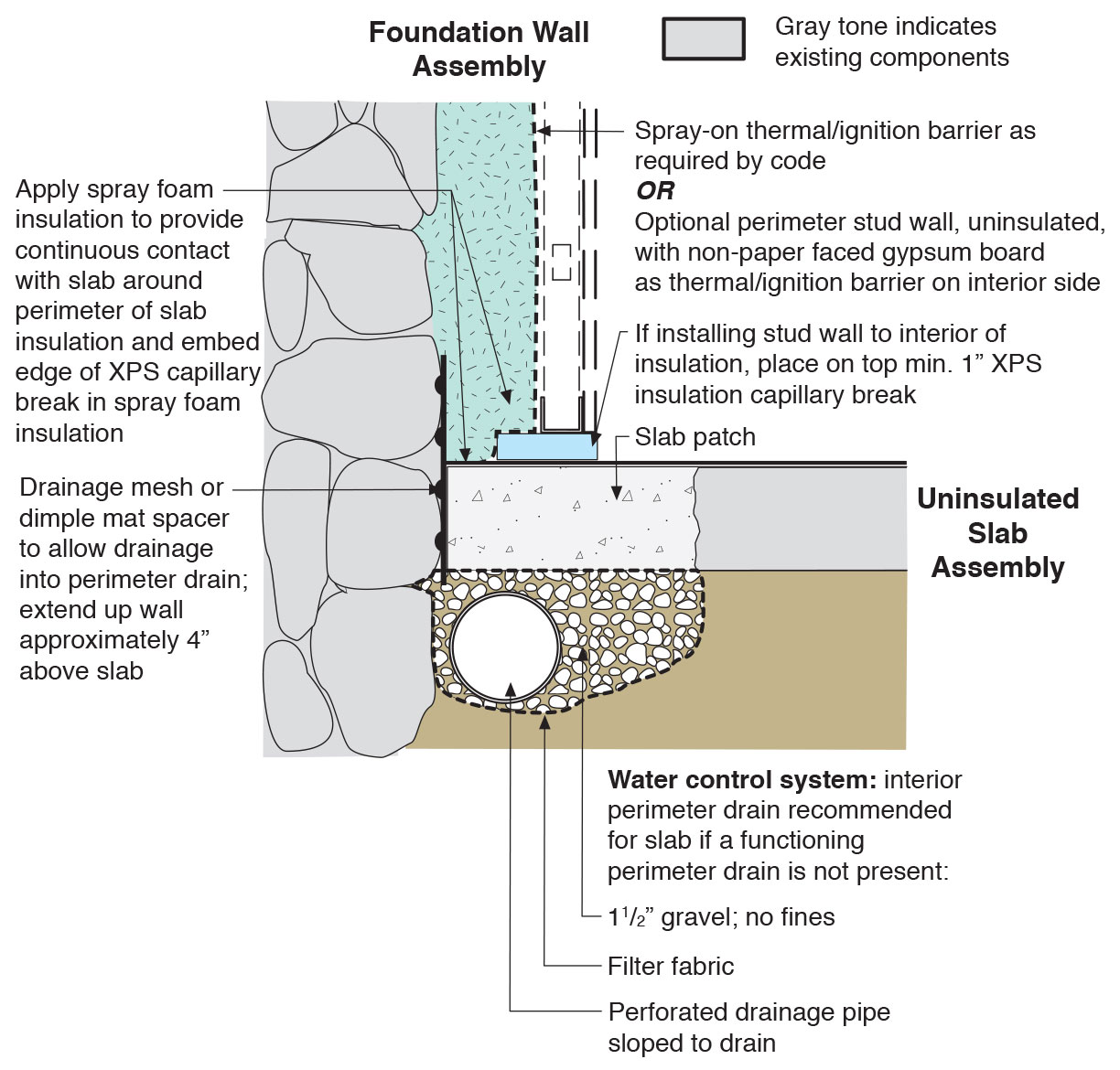
It bears repeating that proper moisture management is critical for basements. The figures in these sections show examples of moisture control strategies that may or may not be appropriate for a specific home. Proper water management should be assessed on a case-by-case basis. For a much more extensive description of water management, insulation, and air-sealing of basements, together with numerous detailed construction drawings, see the report Foundation Design Handbook by Oak Ridge National Laboratory and the University of Minnesota (2014).
Ensuring Success
MOISTURE MANAGEMENT
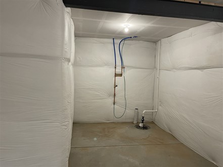
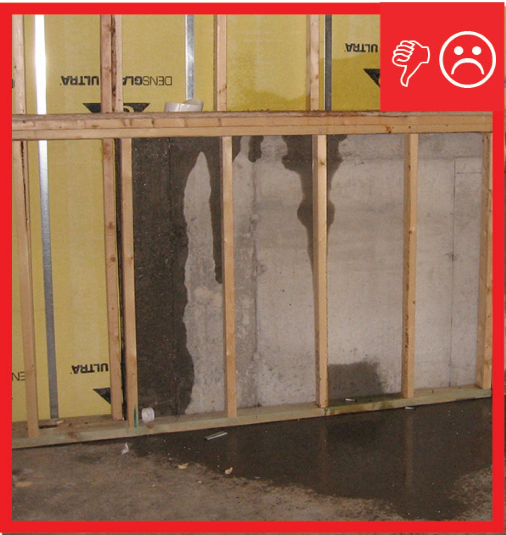
Basements are essentially holes in the ground. As such, they are susceptible to filling with water. Water management is critical in providing for overall durability and healthy basement conditions. Water issues can be related to rain or storm water run-off, ground water intrusion, movement of moist air, water vapor movement, or bulk water leaks from inside the basement (e.g., plumbing leaks). Insulating basement walls without adequately addressing moisture management can simply mask problems down the road. In some cases, insulation can trap water in assemblies and cause more severe problems.
Moisture management MUST be addressed before insulating a basement. There is a great deal of information in the Solution Center on this topic.
INSECT AND PEST MANAGEMENT
Insect problems vary tremendously from region to region and even locally. Termites eat wood, and precautions should be taken for any wood assemblies located near grade. Termites do not eat most insulation products (such as foams and fiberglass), but they can tunnel through these materials to reach food sources in the building.
Termites are not generally visible when they tunnel through insulation. Some codes require a “vision strip,” which is a gap in the insulation that force pests to come out into the open. Vision strips do not stop insects, but they make them more noticeable. In areas with a high likelihood of termites, regular inspections should be conducted. If termites are present, their mud tunnels will likely be visible where they cross the vision strip in search of food. When other pests are identified, other control measures must be taken.
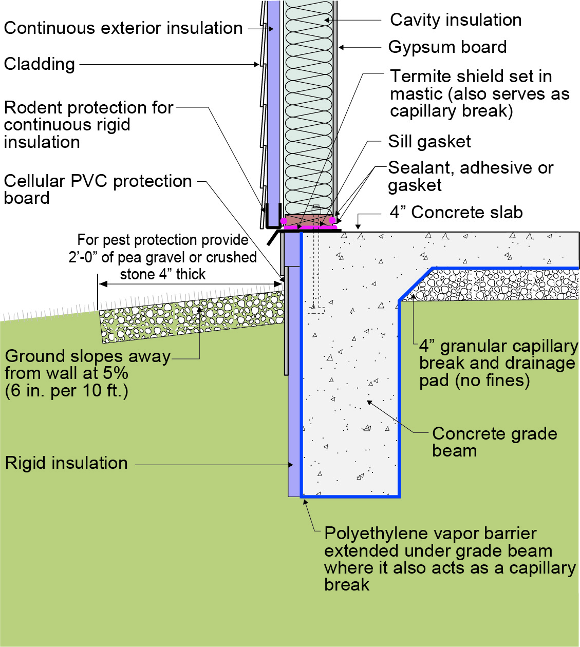
Vision strips have a significant drawback: they require gaps in the insulation. These gaps are generally near grade where insulation is most important thermally because of larger temperature differentials. Where possible, it is recommended to use termite shields rather than insulation gaps in insulation (Figure 1). A termite shield usually consists of a strip of metal flashing that is laid over the top of the foundation wall and below the sill plate. The metal extends out at least 3/4 (0.75) inch from the wall and/or the top of the rigid insulation installed on the interior or exterior surface of the foundation wall. It won’t necessarily stop termites from getting up into the wood framing but, because they can’t chew through the metal, they will have to come out of the insulation to go around it. The mud tunnels they leave on the metal shield will be a visible indicator that they are present. Once detected other pest treatment steps can be taken.
There are also insulation products available including some XPS foam boards with pesticides incorporated into them. Manufacturers of these products often recommend termite shields or similar barriers be used as well.
Termites can represent a substantial durability risk in some areas. Where termites are present, termite shields or other measures should be included in the insulation strategy. If effective pest management cannot be incorporated effectively into the foundation insulation systems, other strategies should be considered, such as insulating beneath the first floor. For more guidance, see "Pests" under "Disaster Resistance" in the Solution Center.
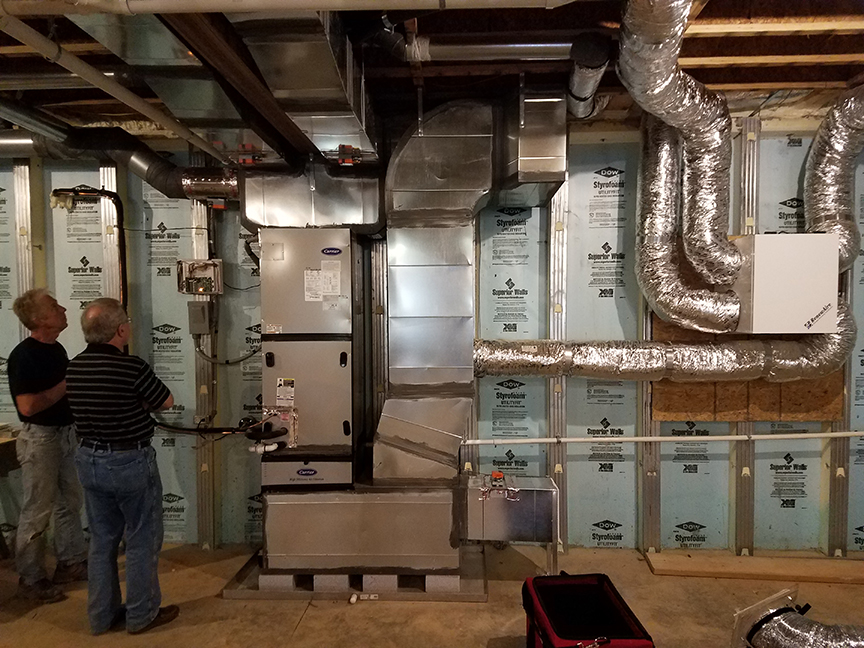
Combustion safety
Basements are often home to combustion appliances such as boilers, furnaces, and water heaters. Atmospherically vented appliances (where exhaust gases are drawn up a flue by natural convection) require substantial amounts of air in the room in which the appliance is located (referred to as the combustion appliance zone or CAZ). When the appliance is located in an uninsulated basement, that air is often drawn through cracks and air leaks around windows and at rim joists. If the basement is later insulated and air sealed, those air sources will be sealed off, which can cause problems with proper combustion and can potentially lead to dangerous conditions like back drafting. Ensure that combustion appliances are operating appropriately and safely before and after sealing and insulating a basement.
The best way to avoid combustion problems is to install non-combustion equipment or sealed-combustion equipment. Sealed-combustion, direct-vented appliances draw air directly from outside through their own dedicated air inlet pipes and they exhaust air directly outside through sealed flues so they do not draw air from the CAZ. If combustion equipment other than sealed-combustion equipment is present in a home, have a qualified contractor assess combustion safety before and after retrofitting, as described in the guides Combustion Appliance Zone Testing and Pre-Retrofit Assessment of Combustion Appliances.
radon
Radon is a radioactive gas that occurs naturally in some soils and rocks and can cause health problems at higher concentrations. For more information on radon testing and mitigation, see this Solution Center guide on radon mitigation and the EPA website Radon-Resistant New Construction Builder/Contractor Resources.
Region
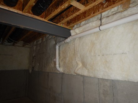
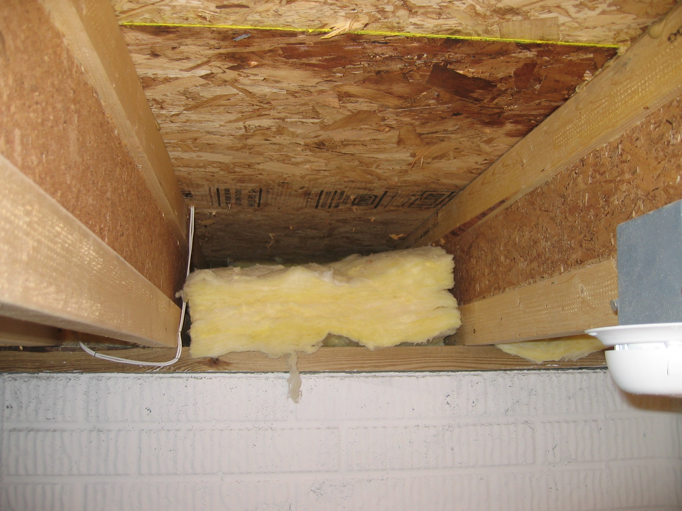
During warm seasons in humid climates, humid air can leak into an air-sealed basement through cracks, such as around windows and rim joists. This humid air can condense on cooler surfaces such as floor joists or below-grade wall surfaces, causing moisture issues in the basement. In cold climates an uninsulated basement can expose HVAC equipment and plumbing located therein to excessively cold temperatures.
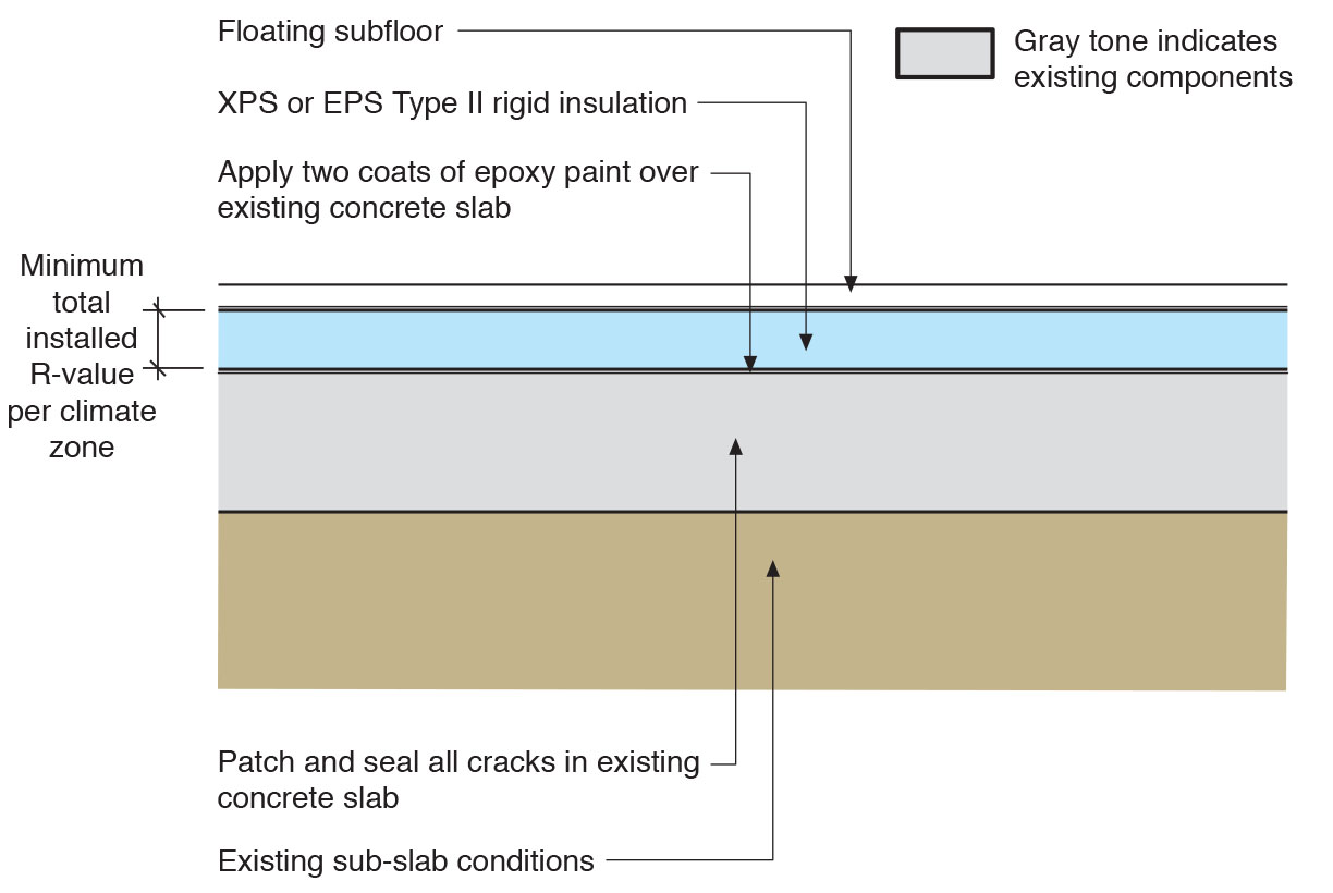
Minimum insulation levels for basements are specified by climate zone in the International Energy Conservation Code (IECC). The insulation levels for the past several IECC and IRC code versions (2009, 12, 15, 18, and 21) are summarized in the Solution Center in the 2009-2021 IECC and IRC Minimum Insulation Requirements for New Homes. See the Compliance tab for relevant code information.
To determine your climate zone see the maps below or go to the 2021 IECC Climate-Specific Building Assemblies tool in the Solution Center and click on the “Help me find by Climate Zone”: button. The map in Figure 1 shows the climate zones for states that have adopted energy codes equivalent to the 2009, 12, 15, and 18 IECC. The map in Figure 2 shows the climate zones for states that have adopted energy codes equivalent to the IECC 2021.
Consult with local code authorities regarding foundation inspection requirements for termites and requirements for radon mitigation. Also see the Description and Success tabs for more information and resources on these topics.

Source
2012 edition of code establishing a baseline for energy efficiency by setting performance standards for the building envelope (defined as the boundary that separates heated/cooled air from unconditioned, outside air), mechanical systems, lighting systems and service water heating systems in homes and commercial businesses.

Source
2021 edition of code establishing a baseline for energy efficiency by setting performance standards for the building envelope (defined as the boundary that separates heated/cooled air from unconditioned, outside air), mechanical systems, lighting systems and service water heating systems in homes and commercial businesses.
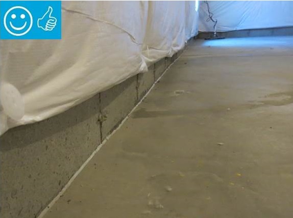
Cold Climates
In all climates, but especially in cold climates where there are concerns about frost heave, ensure the ground surface slopes away from the foundation. Also ensure good vertical drainage along foundation wall by backfilling with free-draining soil or installing geotextile drainage mat on the exterior of foundation walls, and good horizontal drainage with exterior footing drain pipe.
Pests
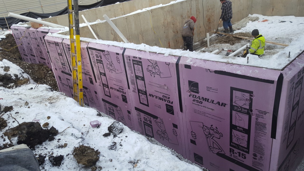
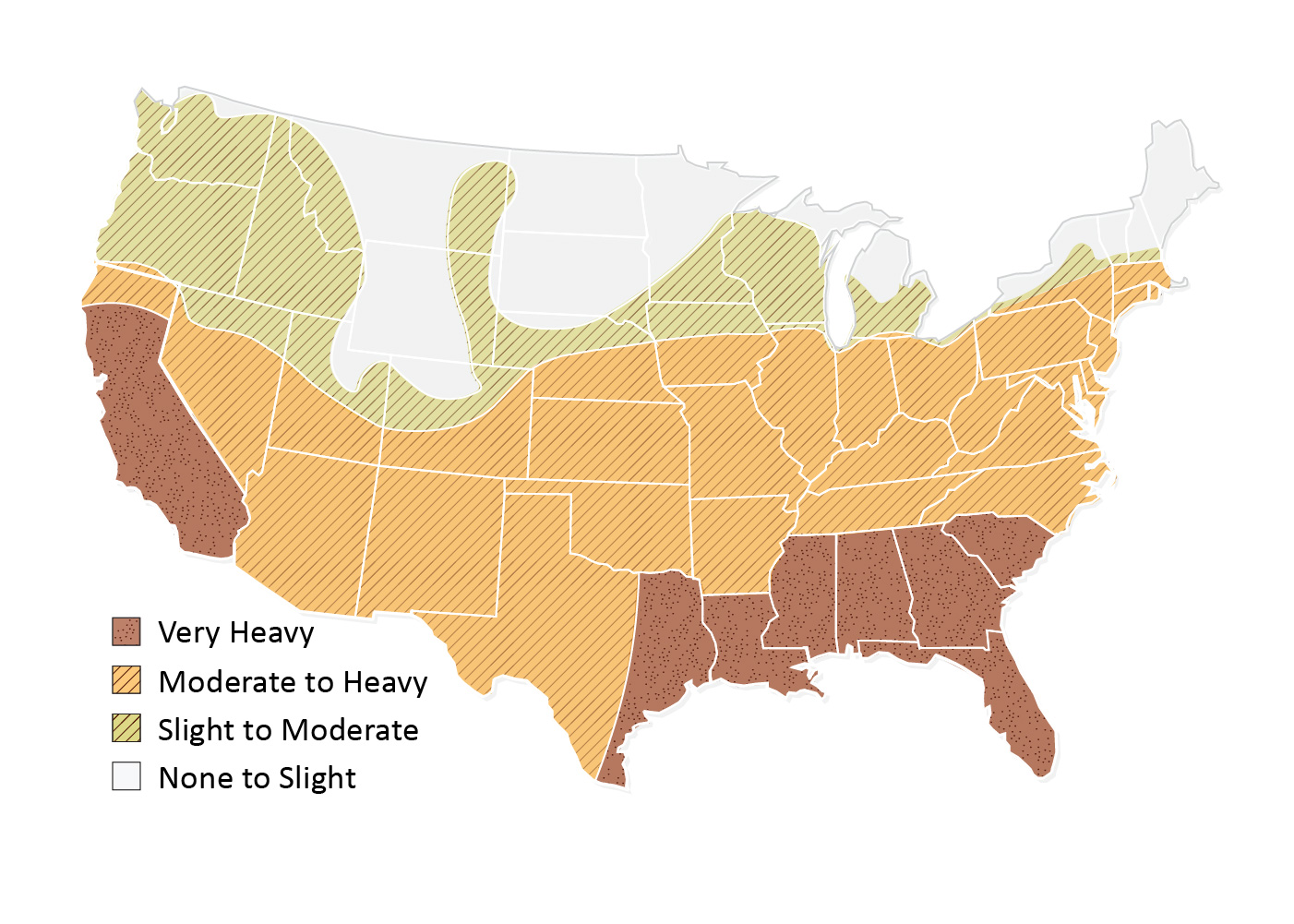
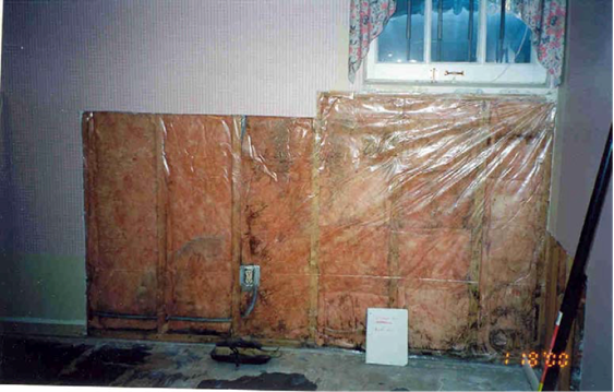
Where termite infestation is heavy (Figure 3), install termite shields at the top of the foundation wall beneath the sill plate that extend out of the wall at least 3/4 (0.75) inch on either side of the sill plate. If rigid foam is installed on the basement wall, leave a termite inspection strip or gap in the insulation to allow inspection of the wall for the presence of termite tunnels, as described in the Success tab.
Source
Training
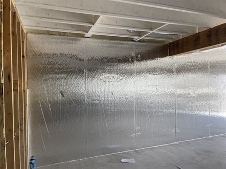
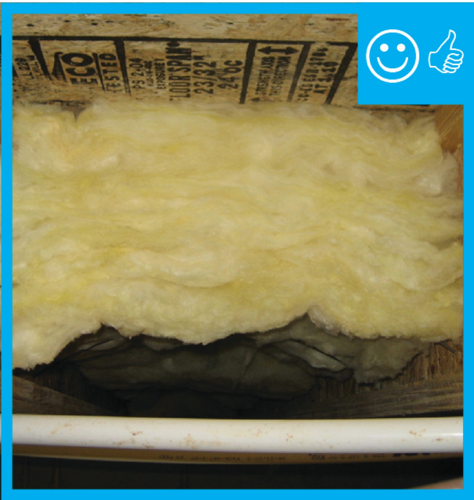
Right and Wrong Images
Source

Source
Source
Source
Website providing the technical specifications and related documents for home builders, subcontractors, architects, and other housing professionals interested in certifying a home to the EPA's Indoor airPLUS program requirements.
Source
Handbook providing guidance on the design and construction of foundations for homes, including insulation, air sealing, and water management details for basements, crawlspaces, and slabs.
Source
Handbook providing guidance on the design and construction of foundations for homes, including insulation, air sealing, and water management details for basements, crawlspaces, and slabs.
Source
Guidebook providing useful examples of high performance retrofit techniques for the building enclosure of wood frame residential construction in a cold and somewhat wet climate.
Source
Handbook providing guidance on the design and construction of foundations for homes, including insulation, air sealing, and water management details for basements, crawlspaces, and slabs.
Source
Source
Handbook providing guidance on the design and construction of foundations for homes, including insulation, air sealing, and water management details for basements, crawlspaces, and slabs.
Source
Handbook providing guidance on the design and construction of foundations for homes, including insulation, air sealing, and water management details for basements, crawlspaces, and slabs.
Source
Handbook providing guidance on the design and construction of foundations for homes, including insulation, air sealing, and water management details for basements, crawlspaces, and slabs.
Source
Source
Source
Source
Source
Source
Source
Source
Source
Handbook providing guidance on the design and construction of foundations for homes, including insulation, air sealing, and water management details for basements, crawlspaces, and slabs.
Source
Handbook providing guidance on the design and construction of foundations for homes, including insulation, air sealing, and water management details for basements, crawlspaces, and slabs.
Source
Source
Guidebook providing useful examples of high performance retrofit techniques for the building enclosure of wood frame residential construction in a cold and somewhat wet climate.
Source
Source
Source
Source
Report providing extensive guidance on controlling moisture in building envelopes through proper selection and installation on air, water, thermal, and vapor barriers.
Source
Handbook providing guidance on the design and construction of foundations for homes, including insulation, air sealing, and water management details for basements, crawlspaces, and slabs.
Source
Handbook providing guidance on the design and construction of foundations for homes, including insulation, air sealing, and water management details for basements, crawlspaces, and slabs.
Source
Handbook providing guidance on the design and construction of foundations for homes, including insulation, air sealing, and water management details for basements, crawlspaces, and slabs.
Source
Handbook providing guidance on the design and construction of foundations for homes, including insulation, air sealing, and water management details for basements, crawlspaces, and slabs.
Source
Source
Source
Source
Source
Guide describing details that serve as a visual reference for each of the line items in the Thermal Enclosure System Rater Checklist.
Source
Guide describing details that serve as a visual reference for each of the line items in the Water Management System Builder Checklist.
Source
Source
Source
Source
Source
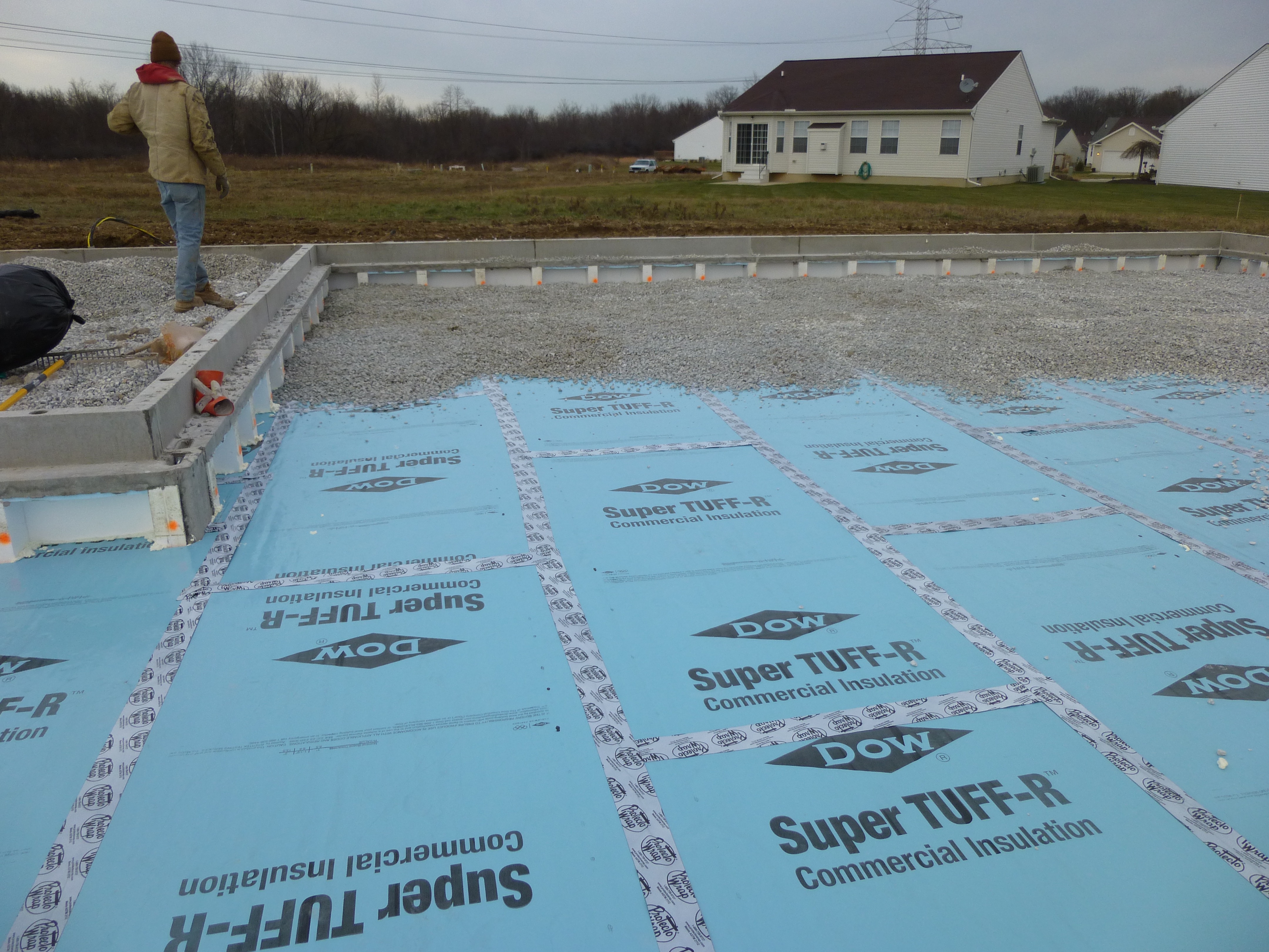
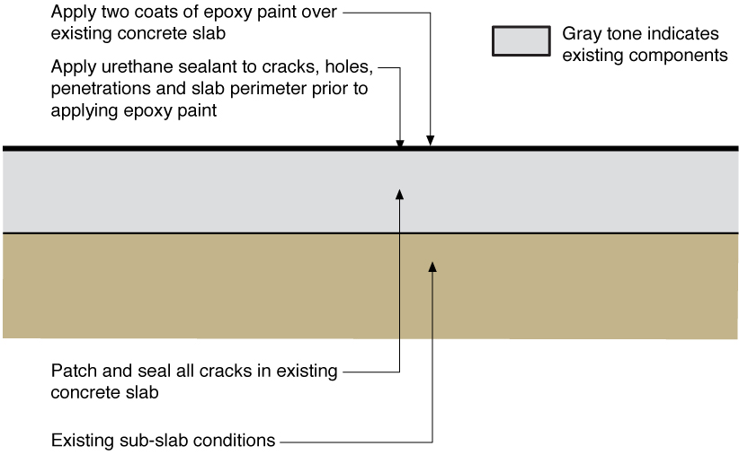
Information sheet about insulating slabs.
Source
Source
Guide describing details that serve as a visual reference for each of the line items in the Thermal Enclosure System Rater Checklist.
Source
Source
Source
Source
Source
Information sheet with methods for constructing or retrofitting basements to reduce moisture issues.


Source
Presentation describing the challenges of insulating an existing basement, presented to the Building America residential energy-efficiency stakeholder meeting.
Source
Source
Information sheet with methods for constructing or retrofitting basements to reduce moisture issues.
Source
Information sheet with methods for constructing or retrofitting basements to reduce moisture issues.
Source
Guide describing details that serve as a visual reference for each of the line items in the Thermal Enclosure System Rater Checklist.
Source
Information sheet with methods for constructing or retrofitting basements to reduce moisture issues.
Source
Guide describing details that serve as a visual reference for each of the line items in the Thermal Enclosure System Rater Checklist.
Source
Guide describing details that serve as a visual reference for each of the line items in the Thermal Enclosure System Rater Checklist.

Source
Source
Guide describing details that serve as a visual reference for each of the line items in the Water Management System Builder Checklist.
Source
Source

Source
Source
Guidebook providing useful examples of high performance retrofit techniques for the building enclosure of wood frame residential construction in a cold and somewhat wet climate.
Source

Source
Guidebook providing useful examples of high performance retrofit techniques for the building enclosure of wood frame residential construction in a cold and somewhat wet climate.
Source
Guidebook providing useful examples of high performance retrofit techniques for the building enclosure of wood frame residential construction in a cold and somewhat wet climate.

Source
Guidebook providing useful examples of high performance retrofit techniques for the building enclosure of wood frame residential construction in a cold and somewhat wet climate.
Source
Source

Source
Source
Document providing information on basement insulation, air sealing and water management retrofits.
Source
Guidebook providing useful examples of high performance retrofit techniques for the building enclosure of wood frame residential construction in a cold and somewhat wet climate.
Source
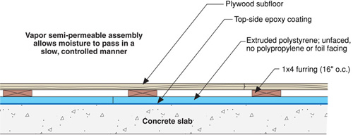
Information guide describing issues with concrete floors, in multiple climate zones.

Source
Source
Source
Presentations

Videos


CAD Files

Compliance
Retrofit
SCOPE
Before considering basement insulation for an existing home, it’s critical to examine several health and durability factors including:
- Structural integrity of foundation
- Combustion safety
- Moisture management
- Pests
- Radon.
Only when these factors are examined (and any problems are addressed) should basement insulation be implemented. See the Success tab for more information on these topics, the Compliance tab for other resources, or the following Building America Solution Center guides for more information:
The U.S. Department of Energy’s Standard Work Specifications has additional information on basements and worker safety in basements.
More Info
Case Studies
References and Resources
*For non-dated media, such as websites, the date listed is the date accessed.
Contributors to this Guide
The following authors and organizations contributed to the content in this Guide.
Steven Winter Associates, Inc. www.swinter.com
Sales
Foundation Wall Water/Damp-Proofing = Foundation Wall Water Barrier
Technical Description
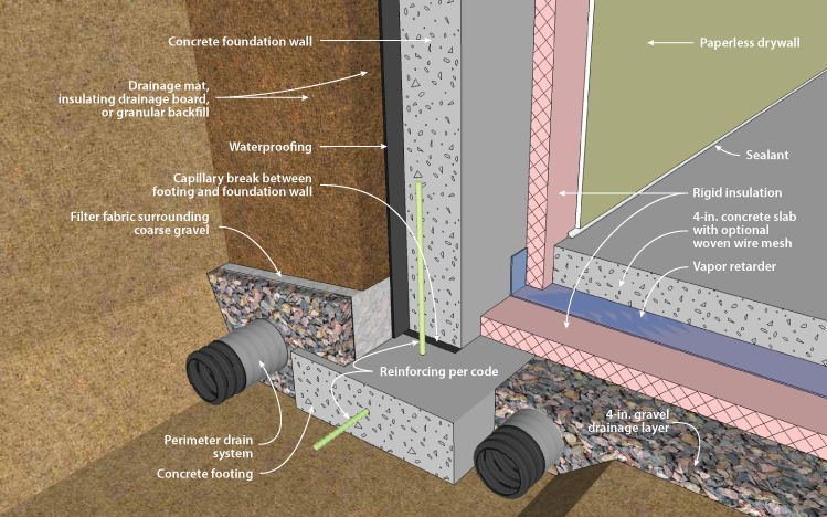
Porous concrete foundations should be treated to avoid water seepage into the home. Builders treat below-grade walls with a damp-proof coating such as an asphalt emulsion. For more reiorous protection, a plastic drainage plane may be used instead of, or in addition to, the damp proof coating. This surface coating may be joined by a layer of insulation. Rigid fiberglass allows water to drain through it; rigid polyurethane foam rated for soil contact is another option. A gravel layer is added to provide a good backfill for draining. This allows water to flow through the gravel toward the foundation footing where a perforated drain pipe will carry it away from the structure.
Questions? Comments? Contact our webmaster.