
Wind Washing

    Scope
    Scope Images
    Image
    Failure in attic insulation effectiveness caused by wind washing pushing insulation away from the edges of the attic space.
    Scope

    Identify areas of the home likely to be affected by wind washing (e.g., attic soffit vents, cantilevered floors, open porch ceilings adjacent to second-story floor cavities).

    • Install baffles at each rafter bay with a soffit vent to direct air flow and wind above rather than through attic insulation. Air seal top plate-drywall seams at ceiling corners.
    • Air seal floor cavities below attic kneewalls and cantilevered floors.
    • Air seal second-story rim joists.
    • Air seal walls separating porch attic areas from the house or house attic.

    See the Compliance Tab for related codes and standards requirements, and criteria to meet national programs such as DOE’s Zero Energy Ready Home programENERGY STAR Single-Family New Homes, and EPA Indoor airPLUS.

    Description
    Description

    Wind washing is the movement of unconditioned air around or through buildings in such a way as to diminish or nullify the intended thermal performance of the home. Wind washing can occur in attics that are vented at the soffits. It can also occur in areas of a home where conditioned spaces abut unconditioned space, for example in areas that are cantilevered (i.e., sections that bump out above the foundation) if those areas are not adequately air sealed with complete air barriers to prevent air from flowing through the floor joist cavities connecting the cantilevered area to the rest of the home. Symptoms of wind washing including cold or hot spots along exterior walls, along second-story walls that border attic spaces, over cantilevered floors, and over or along other areas of the home that border unconditioned spaces.

    Air can enter a house by means of natural infiltration (driven by wind and temperature differential forces) and by means of mechanical infiltration (driven by the heating, cooling, and ventilation mechanical systems). Natural infiltration comes into the house from outside through a variety of pathways. Mechanically induced infiltration is driven by exhaust fans, dryers and duct leakage, which can create a negative pressure inside the home, drawing unconditioned air inside.

    A common example of wind washing is when wind blows through soffit vents and pushes the attic insulation back away from the edges of the ceiling deck, leaving patches of ceiling deck bare along the outer edges of the attic. Where wind washing occurs, rooms will feel hot in the summer and cold in the winter, especially along exterior walls. This kind of wind washing can be prevented by installing baffles, which are cardboard or plastic panels installed in each roof rafter bay with a soffit vent to direct air up past the insulation and along the underside of the roof deck toward the ridge vents. The sides of the baffles are stapled to the attic ceiling or rafters; the baffles provide a 1-2-inch gap between the ceiling and the insulation to serve as a chute for ventilation air to flow from the soffit vents to the attic ridge vents. The lower edge of baffle typically angles down and is sealed to the attic floor just inside of the soffit vent; thus, it provides both a dam to keep insulation from falling through the vent and a solid barrier to keep wind from flowing laterally through the insulation. For more on the installation and use of baffles, see the guide Attic Eave Minimum Insulation.

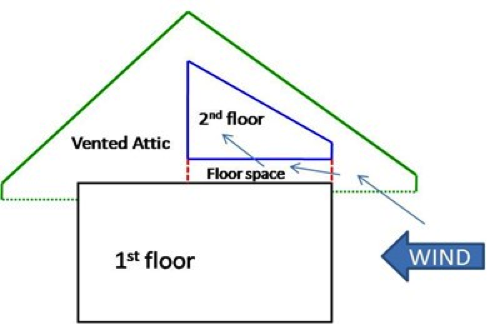
    Wind can also enter the attic or cavities between floors from cantilevered floors that aren't properly air sealed and from porches if the wall between the house and the porch attic is not properly air sealed. Wind that is allowed to flow laterally through the attic can get into interstitial floor spaces, such as under attic kneewalls (Figure 1). (For techniques for insulating and air sealing attic kneewalls, see the guide Attic Knee Walls.) 

    In cooling-dominated periods or climates, wind blowing into attic vents can push hot attic air into the inter-story floor or knee wall cavity, bypassing the typical thermal boundaries of the building and introducing considerable heat into the house. Even in the absence of wind, thermal buoyancy can create air transfer between a hot attic and the interstitial cavities. Wind washing can also occur when little or no attic is involved, where outdoor air can infiltrate directly into the floor cavities or knee walls. These breaches of the air and thermal boundaries of the house can lead to significant entry of sensible heat and, in humid climates, latent heat (water vapor) into the structure. Wind washing has been identified as a significant issue impacting energy demand, comfort, and humidity in two-story homes. Wind washing can result in substantially increased second-story cooling or heating loads. When the outside air is hotter than the inside conditioned air, first-floor cooling loads can increase due to warmer ceilings and air penetration from the floor cavity through recessed lights and other ceiling pathways (Cummings et al. 2009). Factors contributing to increased energy losses due to wind washing include the size and amount of openings between unconditioned spaces and interstitial spaces, the temperature of the air pushed into the floor cavities from the attic space (attics with tile or light-colored roofs and taller roofs will tend to be cooler in summer than dark, asphalt-shingled, and low roofs); the presence of complimentary holes on the opposite side of the building cavity from the prevailing winds, and the prevalence and strength of the wind.

    Windwashing can be prevented at initial construction by ensuring that exterior walls, cantilevered floors, and attic kneewalls are properly air sealed; and by specifying unvented attics, or by properly designing the attic eave area and installing insulation dams and baffles. The level of effort needed to repair areas impacted by wind washing can vary greatly depending on the difficulty of accessing the repair areas and the total area needing to be sealed. 

    Wind washing reduces the effectiveness of attic insulation by pushing insulation away from the edges of the attic space.
    Figure 1. Wind washing reduces the thermal performance of the home by pushing unconditioned air through insulation and into interstitial spaces causing unwanted heat loss or heat gain. (Source: Cummings, Withers, and LaHiff, 2009.)


    How to Prevent Wind Washing in New Construction

    1. In a vented attic, install baffles and insulation dams in each rafter bay with a soffit vent. See the guide Attic Eave Minimum Insulation.
      OR
      Design the home with an unvented attic. See the guide Unvented Attic Insulation.
    2. Air seal cantilevered floors. See the guide Cantilevered Floor.
    3. Air seal attic kneewalls. See the guide Attic Knee Walls.
    4. Air seal walls between porch attics and the house or attic. See the guide Walls Adjoining Porch Roof.

    How to Locate Areas of Wind Washing in Existing Construction

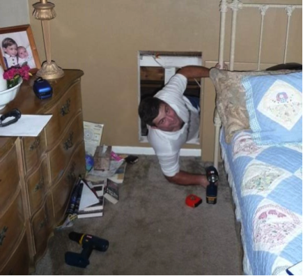
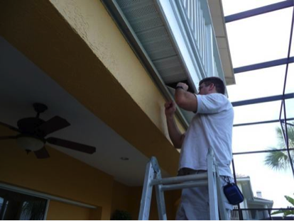
    1. Visually inspect potential areas, along attic eaves, under cantilevered floors, and under attic kneewalls to see if the air barrier is incomplete or missing. These spaces may be difficult or impossible to physically access (Figure 2).  Some disassembly or borescope investigations may be needed (Figure 3). 
    2. Use a blower door for floor cavity diagnostic pressure testing to determine the pressure difference between the house and the first-second floor cavity.
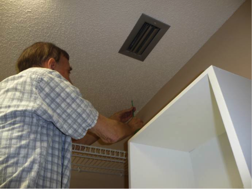
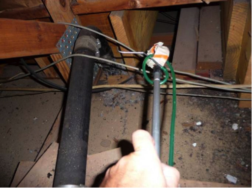
      • Place the reference tube inside the cavity of the floor between the first and second stories. This can be done by drilling a small hole through first-floor ceiling into the floor cavity (Figure 4), by pushing the end of the tube into the space with an extension pole from within the attic (Figure 5), or by pushing the tube through a leaky can light or other ceiling fixture located in the floor cavity.
      • Set up the blower door and bring the house to -50 Pa with respect to (wrt) the outdoors; turn off all HVAC.
      • Measure the house wrt to the floor cavity pressure.
      • With the house depressurized by the blower door to -50 Pa, the house pressure is measured wrt the floor cavity. The house wrt floor cavity will be negative (less than zero) as long as the floor cavity has some connection to a vented attic space. (This test could also be done in the pressurization mode if preferred.) If the floor cavity is much more connected to a vented attic space, the reading will be closer to -50 Pa. If the floor cavity is relatively tight to the attic and leakier to the indoor space, the reading will be closer to 0 Pa. Use of an IR camera while the blower door test is underway will help you identify the locations of greatest air flow and heat loss. If the measurement is -34 Pa or more negative, more detailed visual investigation of the floor cavity is warranted.
    Limited attic access can make inspections for missing air barriers and insulation challenging.
    Figure 2. Limited attic access can make inspections for missing air barriers and insulation challenging.


    Limited attic access may make it necessary to use a bore scope when inspecting for missing air barriers and insulation.
    Figure 3. Limited attic access may make it necessary to use a bore scope when inspecting for missing air barriers and insulation.


    Floor cavity air pressure is measured by placing a tube into the floor cavity through a small drilled hole.
    Figure 4. Floor cavity air pressure is measured by placing a tube into the floor cavity through a small drilled hole.


    Floor cavity pressure is measured by inserting a tube into the floor cavity using an extension pole.
    Figure 5. Floor cavity pressure is measured by inserting a tube into the floor cavity using an extension pole.


    How to Repair Attic Areas Affected by Wind Washing

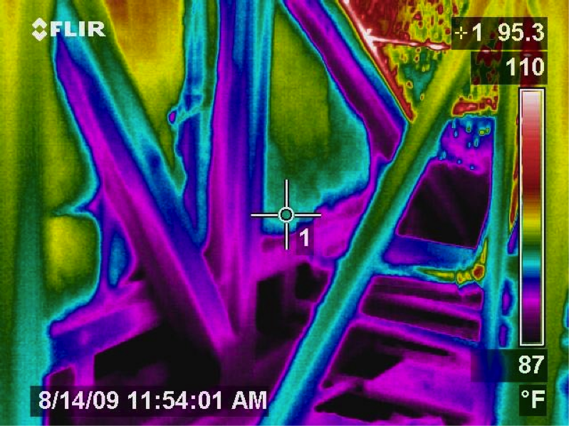
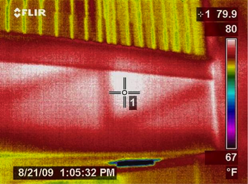
    1. Inspect for locations of wind washing using visual inspection, blower door testing, and infrared thermography as described above.  Locate open floor joist cavities under second stories and other uninsulated, un-airsealed areas that connect to ventilated unconditioned space. Figure 6 shows an attic kneewall that is insulated but the floor joist cavities underneath this second-story room are completely open to the vented attic, allowing unconditioned air to flow through the floor space. Figure 7 shows the same view with an infrared camera. The dark purple and blue areas show cold conditioned air pouring into the hot attic from the interstitial floor space.
    2. Air seal the open floor joists with spray foam, rigid foam or another solid sheet good that is cut to fit and sealed in place over the open joist cavities with caulk or foam. The space could also be filled with rolled fiberglass batt insulation that is stuffed into each cavity and covered with spray foam to air seal.
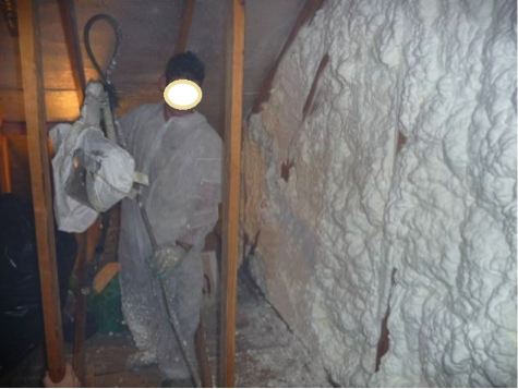
    3. Add insulation to the attic knee wall if the wall is currently uninsulated, under insulated, or poorly insulated. The wall should be airsealed by caulking all holes and seams prior to insulating. If it is not desirable to remove the existing insulation to air seal the wall, than the wall can be airsealed by spray foaming (or installing a rigid air barrier that is sealed at all seams) over the fibrous insulation. The wall and floor joist cavities can be sealed and insulated in one step by using spray foam as shown in Figure 8.
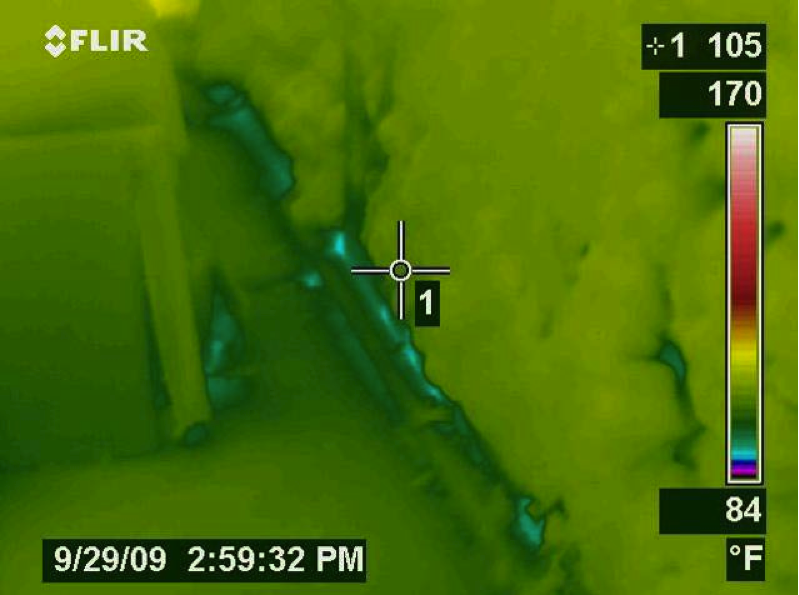
    4. Conduct a post-retrofit inspection including a blower door test and infrared thermography to determine the effectiveness of the repair, as shown in Figure 9.
    5. Install baffles at soffit vents as described in the guide Attic Eave Minimum Insulation to minimize lateral air flow in the attic while maintaining desired ventilation along the underside of the roof deck.
    The floor cavities under this attic kneewall are completely open to the unconditioned attic space and a prime target for wind washing.
    Figure 6. The floor cavities under this attic kneewall are completely open to the unconditioned attic space and a prime target for wind washing.


    Infrared imaging shows cold conditioned air pouring out of the open floor cavities under this attic kneewall into the hot unconditioned attic.
    Figure 7. Infrared imaging shows cold conditioned air pouring out of the open floor cavities under this attic kneewall into the hot unconditioned attic.


    The attic kneewall and the open floor cavities under kneewall are both sealed and insulated in one step with spray foam insulation.
    Figure 8. The attic kneewall and the open floor cavities under kneewall are both sealed and insulated in one step with spray foam insulation.


    Infrared photography shows how effectively the spray foam insulated and air sealed the attic kneewall and the floor cavities under the kneewall almost completely blocking air flow and heat loss under the kneewall.
    Figure 9. Infrared photography shows how effectively the spray foam insulated and air sealed the attic kneewall and the floor cavities under the kneewall almost completely blocking air flow and heat loss under the kneewall.


    Success
    Ensuring Success

    Air seal exterior walls and walls separating porch attics from the home, air seal floor joist cavities under attic knee walls and cantilever floors, and install baffles and insulation dams in vented attics. Use blower door testing in combination with visual inspection and infrared thermography to identify areas of wind washing and to verify repair.

    Climate
    Climate

    Wind washing occurs in all climates. In humid, cooling-dominated climates, ensure that ducts in vented attics are insulated to at least R-8 and covered with a continuous vapor barrier before adding insulation that may come in contact with the ducts. Condensation can form on the exterior of cold air supply ducts that lack adequate insulation and a continuous vapor barrier.

    Training
    Right and Wrong Images
    Image
    Right-- IR photo shows how effectively spray foam insulated/air sealed attic kneewall and the floor cavities under kneewall
    Right-- IR photo shows how effectively spray foam insulated/air sealed attic kneewall and the floor cavities under kneewall
    Image
    Right – This attic knee wall and the floor joist cavity openings beneath it are being sealed and insulated with spray foam.
    Right – This attic knee wall and the floor joist cavity openings beneath it are being sealed and insulated with spray foam.
    Image
    Wrong - This IR image shows where hot attic air has penetrated into the floor cavity that lies behind the stairwell wall
    Wrong - This IR image shows where hot attic air has penetrated into the floor cavity that lies behind the stairwell wall
    Image
    Wrong - This IR image of a second-floor landing shows that attic air is flowing far into the interstitial floor cavity of the second-floor landing
    Wrong - This IR image of a second-floor landing shows that attic air is flowing far into the interstitial floor cavity of the second-floor landing
    Image
    Wrong – This second-story floor plan has red lines that indicate openings from the attic into the interstitial floor space
    Wrong – This second-story floor plan has red lines that indicate openings from the attic into the interstitial floor space
    Compliance

    Compliance

    The Compliance tab contains both program and code information. Code language is excerpted and summarized below. For exact code language, refer to the applicable code, which may require purchase from the publisher. While we continually update our database, links may have changed since posting. Please contact our webmaster if you find broken links.


    ENERGY STAR Single-Family New Homes, Version 3/3.1 (Rev. 11)

    Rater Field Checklist

    Thermal Enclosure System.
    2. Fully-Aligned Air Barriers.7 At each insulated location below, a complete air barrier is provided that is fully aligned as follows:
    Ceilings: At interior or exterior horizontal surface of ceiling insulation in Climate Zones 1-3; at interior horizontal surface of ceiling insulation in Climate Zones 4-8. Also, at exterior vertical surface of ceiling insulation in all climate zones (e.g., using a wind baffle that extends to the full height of the insulation in every bay or a tabbed baffle in each bay with a soffit vent that prevents wind washing in adjacent bays).8​
    2.1 Dropped ceilings / soffits below unconditioned attics, and all other ceilings.

    Footnote 7) For purposes of this Checklist, an air barrier is defined as any durable solid material that blocks air flow between conditioned space and unconditioned space, including necessary sealing to block excessive air flow at edges and seams and adequate support to resist positive and negative pressures without displacement or damage. EPA recommends, but does not require, rigid air barriers. Open-cell or closed-cell foam shall have a finished thickness ≥ 5.5 in. or 1.5 in., respectively, to qualify as an air barrier unless the manufacturer indicates otherwise. If flexible air barriers such as house wrap are used, they shall be fully sealed at all seams and edges and supported using fasteners with caps or heads ≥ 1 in. diameter unless otherwise indicated by the manufacturer. Flexible air barriers shall not be made of kraft paper, paper-based products, or other materials that are easily torn. If polyethylene is used, its thickness shall be ≥ 6 mil.

    Footnote 8) All insulated ceiling surfaces, regardless of slope (e.g., cathedral ceilings, tray ceilings, conditioned attic roof decks, flat ceilings, sloped ceilings), must meet the requirements for ceilings.

    Please see the ENERGY STAR Single-Family New Homes Implementation Timeline for the program version and revision currently applicable in in your state.


    DOE Zero Energy Ready Home (Revision 07)

    Exhibit 1 Mandatory Requirements.
    Exhibit 1, Item 1) Certified under the ENERGY STAR Qualified Homes Program or the ENERGY STAR Multifamily New Construction Program.
    Exhibit 2, Item 2) Ceiling, wall, floor, and slab insulation shall meet or exceed 2015 IECC levels and achieve Grade 1 installation, per RESNET standards.

    Exhibit 2 DOE Zero Energy Ready Home Target Home.
    The U.S. Department of Energy’s Zero Energy Ready Home program allows builders to choose a prescriptive or performance path. The DOE Zero Energy Ready Home prescriptive path requires builders to meet or exceed the minimum HVAC efficiencies listed in Exhibit 2 of the National Program Requirements (Rev 07), as shown below. The DOE Zero Energy Ready Home performance path allows builders to select a custom combination of measures for each home that is equivalent in performance to the minimum HERS index of a modeled target home that meets the requirements of Exhibit 2 as well as the mandatory requirements of Zero Energy Ready Home Exhibit 1.

    Exhibit 2, Insulation and Infiltration) Insulation levels shall meet the 2015 IECC and achieve Grade 1 installation, per RESNET standards. Whole house leakage must be tested and meet the following infiltration limits:

    • Zones 1-2: ≤ 3 ACH50;
    • Zones 3-4: ≤ 2.5 ACH50;
    • Zones 5-7: ≤ 2 ACH50;
    • Zone 8: ≤ 1.5 ACH50;
    • Attached dwellings: ≤ 3 ACH50.

    Footnote 23) Envelope leakage shall be determined by an approved verifier using a RESNET-approved testing protocol.


    2009 International Energy Conservation Code (IECC)

    Table 402.4.2, Air barrier and thermal barrier: Exterior wall insulation is installed in substantial contact and continuous alignment with the air barrier. Air permeable insulation is not used as a sealing material.

    2012 IECC

    The IECC 2012 requires new construction to have a tested air tightness with whole house air leakage not to exceed 5 ACH50 for Climate Zones 1 and 2. An even tighter restriction of 3 ACH50 is mandatory for Climate Zones 3 through 8. IECC 2012 has language in Table R402.4.1.1 that may be interpreted that floor cavities are required to be insulated and air sealed from unconditioned spaces, however floor cavities are not specifically mentioned. Without more specific language addressing floor cavities, code enforcement is more likely to be missed. Florida code has adopted more specific language that requires an “Air barrier on perimeter of floor cavities between floors” for multi-story homes.

    Table R402.4.1.1, Air barrier and thermal barrier: A continuous air barrier is installed in the building envelope including rim joists and exposed edges of insulation. Breaks or joints in the air barrier are sealed. Air permeable insulation is not used as a sealing material.

    20152018, and 2021 IECC

    Table R402.4.1.1 requires that a continuous air barrier be installed in the building envelope including at the junction of the top plate and the tops of exterior walls, all kneewalls, all rim joists, and at any exposed edges of insulation in floors.

    Retrofit:  2009, 2012, 2015, 2018,  and 2021 IECC

    Section R101.4.3 (in 2009 and 2012). Additions, alterations, renovations, or repairs shall conform to the provisions of this code, without requiring the unaltered portions of the existing building to comply with this code. (See code for additional requirements and exceptions.)

    Chapter 5 (in 2015, 2018, 2021). The provisions of this chapter shall control the alteration, repair, addition, and change of occupancy of existing buildings and structures.


    2009 International Residential Code (IRC)

    Table N1102.4.2, Air barrier and thermal barrier: Exterior wall insulation is installed in substantial contact and continuous alignment with the air barrier. Air permeable insulation is not used as a sealing material.

    2012 IRC

    Table N1102.4.1.1, Air barrier and thermal barrier: A continuous air barrier is installed in the building envelope including rim joists and exposed edges of insulation. Breaks or joints in the air barrier are sealed. Air permeable insulation is not used as a sealing material.

    20152018, and 2021 IRC

    N1102.4.1.1 Air Barrier and Insulation Installation, Ceiling/attic: Air barrier in any dropped ceiling/soffit is substantially aligned with insulation and any gaps are sealed. General requirements: A continuous air barrier is installed in the building envelope; breaks and joints in the air barrier are sealed. Air-permeable insulation is not used as an air-sealing material.

    Retrofit:  2009, 2012, 2015, 2018,  and 2021 IRC

    Section R102.7.1 Additions, alterations, or repairs. Additions, alterations, renovations, or repairs shall conform to the provisions of this code, without requiring the unaltered portions of the existing building to comply with the requirements of this code, unless otherwise stated. (See code for additional requirements and exceptions.)

    Appendix J regulates the repair, renovation, alteration, and reconstruction of existing buildings and is intended to encourage their continued safe use.

    More

    More Info.

    Access to some references may require purchase from the publisher. While we continually update our database, links may have changed since posting. Please contact our webmaster if you find broken links.

    Case Studies
    References and Resources*
    Author(s)
    Lstiburek Joseph W
    Organization(s)
    Building Science Corporation,
    BSC
    Publication Date
    Description
    The Builder's Guide provides the building industry with the latest and best practical information on how to apply building science principles to structures as systems in hot-humid climate regions.
    Author(s)
    Southface Energy Institute,
    Oak Ridge National Laboratory
    Organization(s)
    ORNL,
    SEI
    Publication Date
    Description
    Information sheet with information about insulating and ventilating attics.
    *For non-dated media, such as websites, the date listed is the date accessed.
    Contributors to this Guide

    The following authors and organizations contributed to the content in this Guide.

    Pacific Northwest National Laboratory

    Building America Partnership for Improved Residential Construction/Florida Solar Energy Center

    Sales
    Building Science Measures
    Building Science-to-Sales Translator

    Fully Aligned Air Barriers = Whole-House Draft Barrier

    Image(s)
    Technical Description

    A whole-house draft barrier is a continuous layer of air-tight materials that block air leaks. This barrier can be integrated with other materials to also function as a water barrier, thermal barrier, and vapor barrier. For example, rigid foam insulation can be used to block thermal flow as well as air flow when seams are sealed with tape, caulk, adhesives, or liquid-applied sealants. Some rigid foams have an integrated water control layer as well. Additionally, drywall can serve as an interior air barrier when the seams are taped and spackled, and caulk, spray foam, or gaskets are used to seal around wiring, plumbing, and other penetrations. It also serves as the vapor barrier when finished with paint. Insulation should be in full contact with the air barrier layer.

    Whole-House Draft Barrier
    Sales Message

    Whole-house draft barriers block air flow that can undermine the thermal protection with a complete high-performance insulation system. What this means to you is less wasted energy along with enhanced comfort, quiet, and durability. Wouldn’t you agree it would be a shame to only get a partial return on your investment in advanced insulation?

    Last Updated

    Did you find this information helpful?

    If you have questions and/or would like a reply to this feedback, please include your e-mail address in the message.
    This question is for testing whether or not you are a human visitor and to prevent automated spam submissions.