
Unvented Attic Insulation

    Scope
    Scope Images
    Image
    An unvented cathedralized attic has the air, thermal, and vapor control layers at the roof line
    Scope

    Install insulation along the underside of the roof deck of an unvented attic rather than on the ceiling deck of a vented attic for either of two reasons:  to provide an unvented, conditioned space for locating HVAC equipment in the attic, and/or to provide a continuous thermal barrier for designs that have complex coffered ceiling planes and/or numerous penetrations for lights, speakers, vents, soffits, etc., which make it difficult to achieve an airtight ceiling plane.

    Install insulation to levels that meet or exceed code or energy-efficiency program requirements.

    See the Compliance Tab for related codes and standards requirements, and criteria to meet national programs such as DOE’s Zero Energy Ready Home programENERGY STAR Single-Family New Homes, and EPA Indoor airPLUS.

    Description
    Description

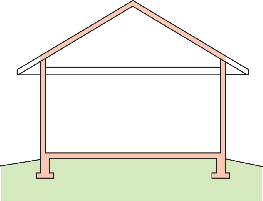
    Unvented roof assemblies, such as conditioned attics and unvented cathedral ceilings, are created by eliminating ventilation openings and moving the thermal (insulation), moisture, and air control boundaries to the plane of the roof deck. These unvented cathedralized attic assemblies (also known as a “compact” or “hot roof” assemblies) can be used to overcome two major problems associated with vented attics:

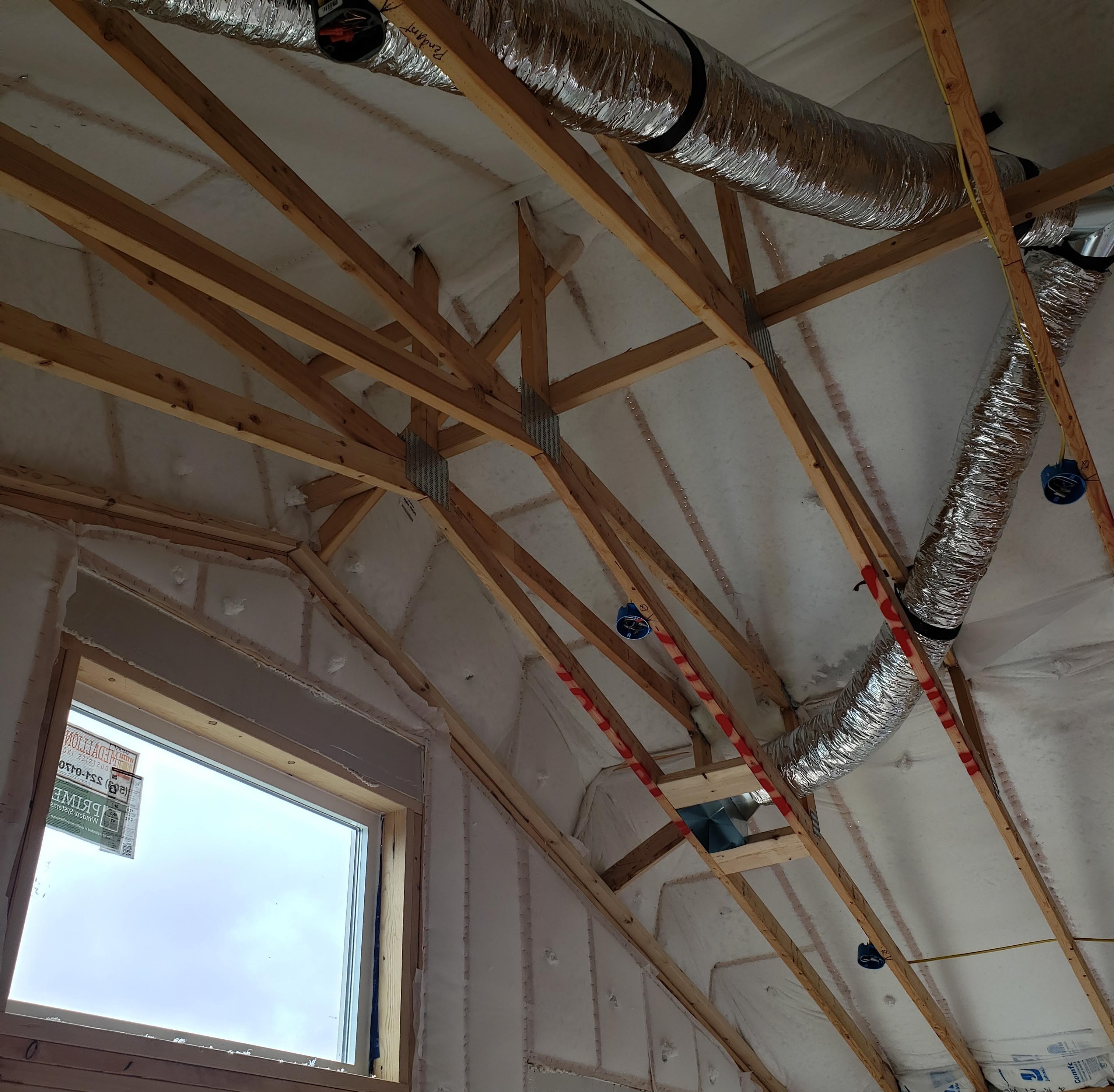
    1. Locating ducts/air handling units in the attic space can be a cause of major air leaks of conditioned air to unconditioned space (and thus forced infiltration/exfiltration), and heat/loss gain through the ductwork.
    2. Designs with complex coffered ceiling planes, and numerous penetrations by lights, speakers, vents, etc., make it practically difficult to achieve the airtightness required just below the insulation layer.

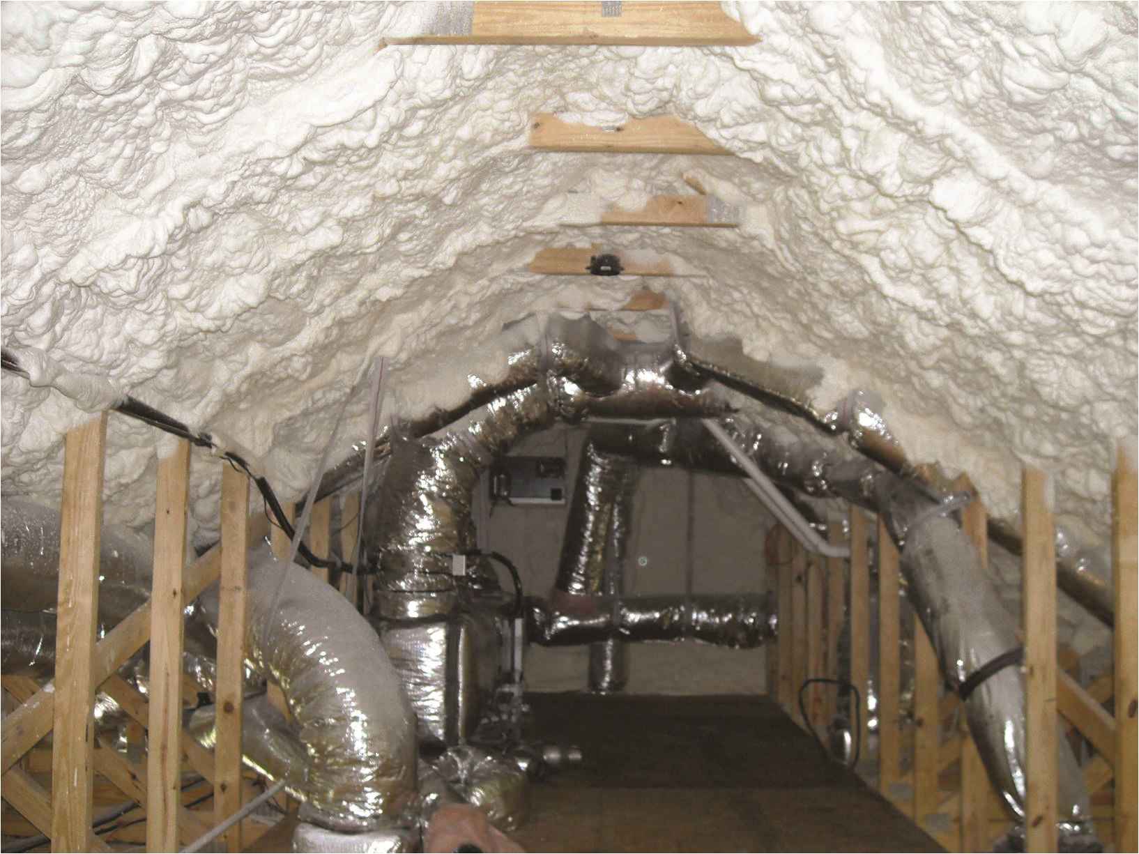
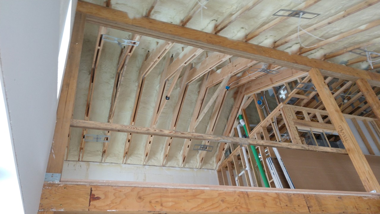
    In cases where mechanical systems are located in attics, moving the air control layer and thermal control layer to the the roof deck has particularly large advantages compared to sealing and insulating attic ceilings and ductwork.  In addition it might not be desirable (in hurricane or wildfire areas) or practical (in retrofit) to add roof vents at soffit locations.  Accordingly, there may not be any practical alternative to moving the air control layer and thermal control layer to the roof deck (Figure 1). When this design choice is made, spray foams have advantages over alternative insulation methods because of the ability of spray foams to effectively air seal complex assemblies. Spray foam can provide the thermal and vapor control layers in both new and retrofit construction.

    Ductwork in an unvented attic.
    Figure 1. Ductwork in an unvented attic that is insulated along the roof line.


    All unvented attic and cathedral ceiling designs must provide for either a very high degree of airtightness or avoidance of condensation due to warming of cold surfaces. To meet durability goals in most applications, the airtightness must be provided by a continuous membrane—preferably adhered to the top surface of the structural roof deck and under rigid insulation that provides condensation control.  In designs where the air tightness is provided between framing elements, spray foam has been found to be a practical solution.  However, all wood-to-wood joints in the framing must still be sealed. 

    The key to creating an unvented roof assembly is to keep the roof deck – the principle condensing surface in roof assemblies – sufficiently warm throughout the year such that condensation will not occur, or to prevent interior moisture laden air from accessing the roof deck (Lstiburek 2014). This is done by using what is referred to as “air-impermeable insulation,” such as rigid foam board or spray foam.

    Two acceptable methods for insulating an unvented attic assembly in all climates are as follows:

    1. Air-impermeable insulation (typically spray foam) installed to the underside of the roof sheathing. For more information on this technique see the guides Unvented Conditioned Attic with Spray Foam Insulation Below Roof Deck and Below Deck Spray Foam Insulation for Existing Roofs.
    2. Air-impermeable insulation (typically rigid foam insulating sheathing) installed over the roof sheathing. For more information on this technique see the guide Above Deck Rigid Foam Insulation for Existing Roofs.

    In both assemblies, air-permeable insulation (such as batt or loose fill) can be used to increase overall insulation value.  This is by no means a requirement; however, it is typically the most economical way to achieve target (or code minimum) R-values.  Alternately, “air-impermeable insulation” alone could be used for the entire insulation thickness, assuming that all climate-specific code requirements are met (see Climate section).

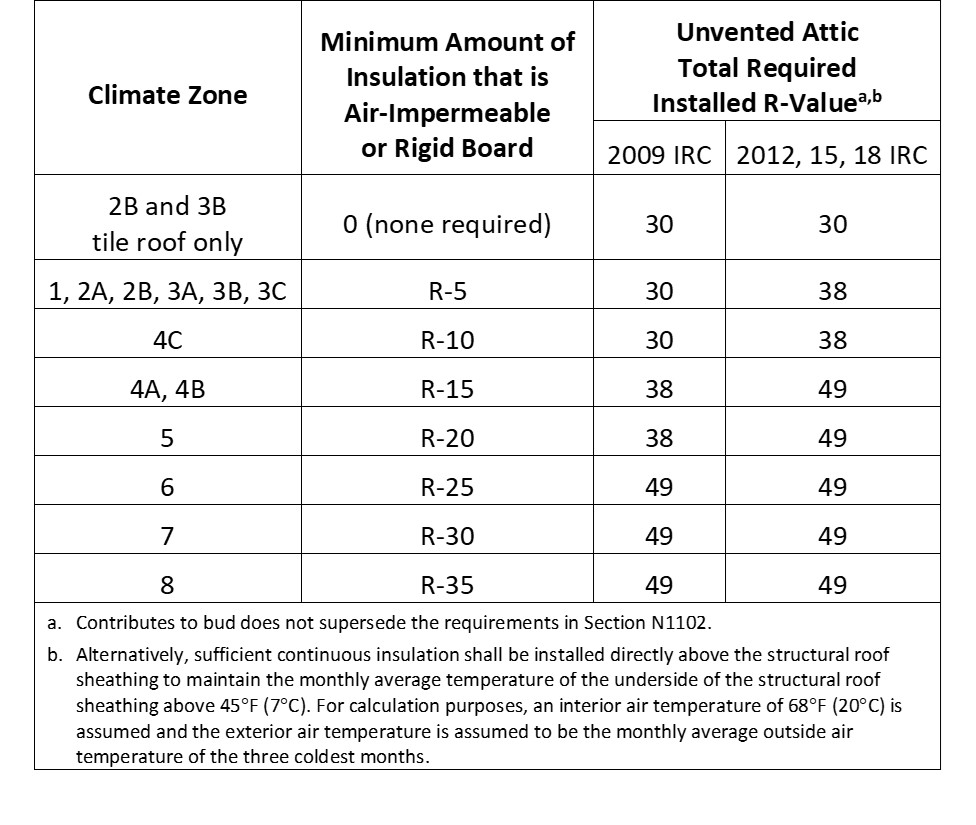
    The minimum required thickness of the “air-impermeable insulation” is stated in Table R806.5 - Insulation for Condensation Control of the 2012 IRC, which provides prescriptive requirements for minimum rigid board or air-impermeable insulation R-values based on climate zone, in order to manage the condensation potential in the assembly. See the Climate tab for details.

    When designing a highly insulated roof (high-R value roof), it is important, especially in cold climates, to note the ratio of vapor-impermeable to vapor-permeable R-values. For cold climates, the air-impermeable insulation is maintained at 50% or more of the total R-value of the roof system. This is for condensation control. When building high-R-value roof systems, Building Science Corporation (BSC) recommends that this ratio be maintained or exceeded. If an R-80 unvented cathedralized attic is to be constructed in a cold climate, it is recommended that a minimum of R-40 (50%) be air-impermeable insulation installed and layered according to Section R806.5 of the 2012 IRC. (see the case study “Application of Spray Foam Insulation Under Plywood and OSB Roof Sheathing” at the More Info tab.)

    Below are general instructions for the two unvented attic designs.

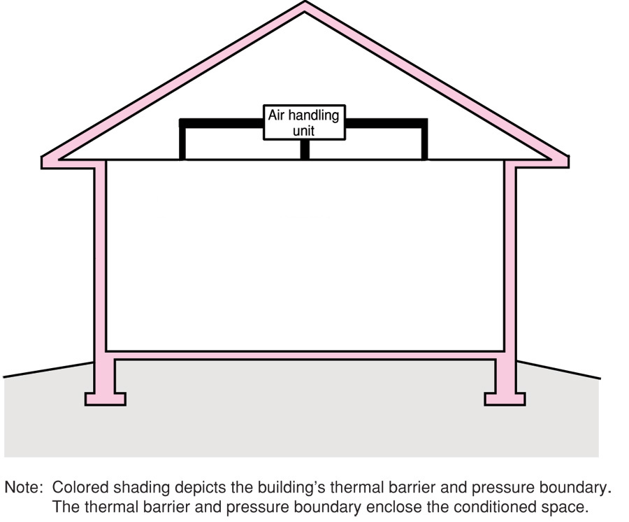
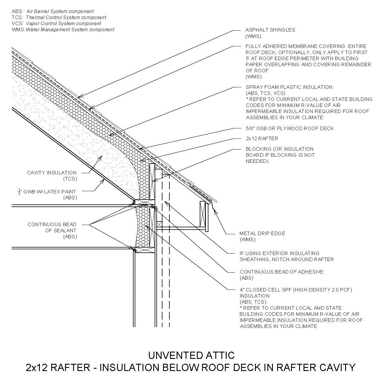
    Air-Impermeable Insulation Installed to the Underside of the Roof Sheathing in a Cathedral Ceiling

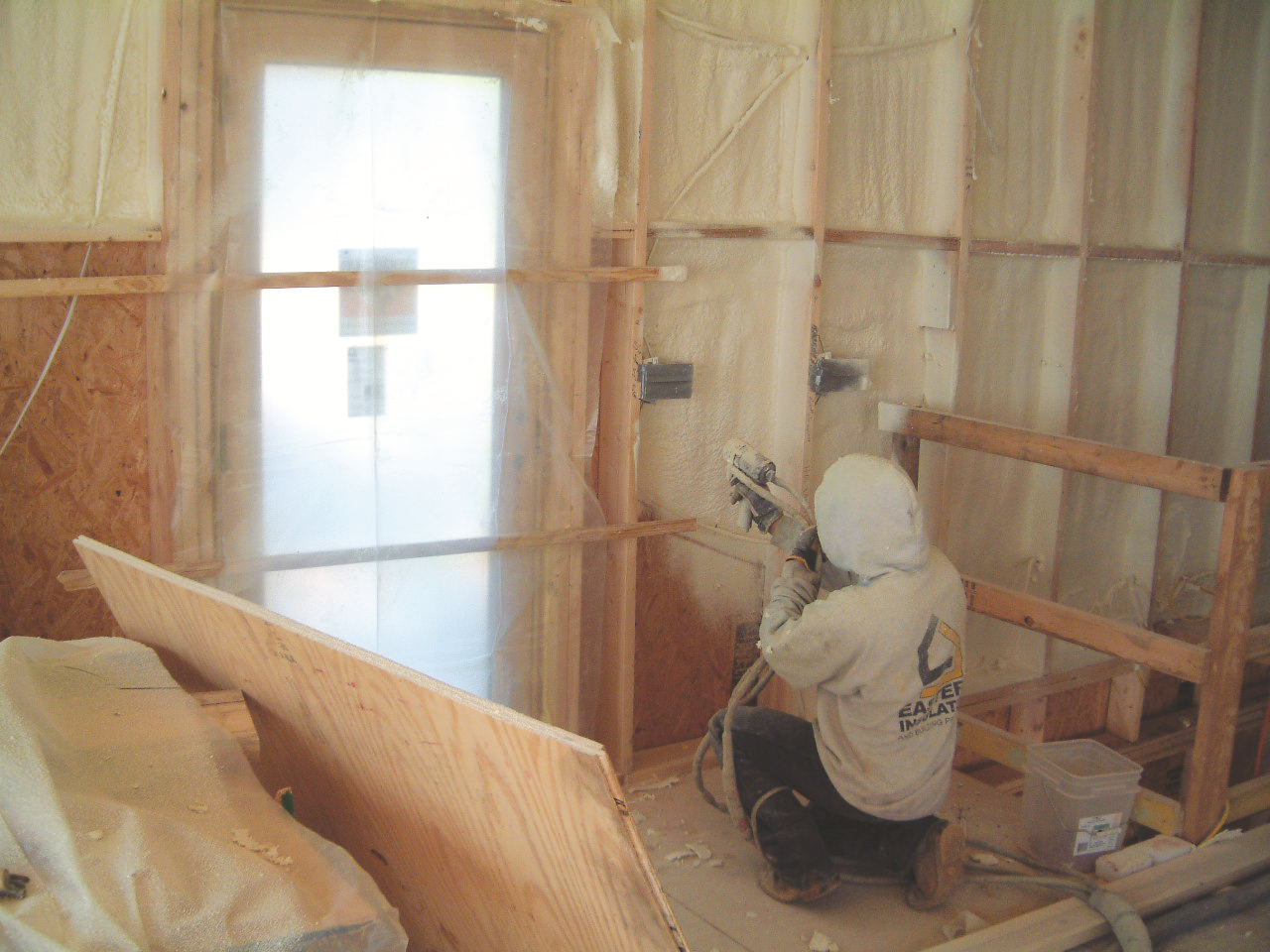
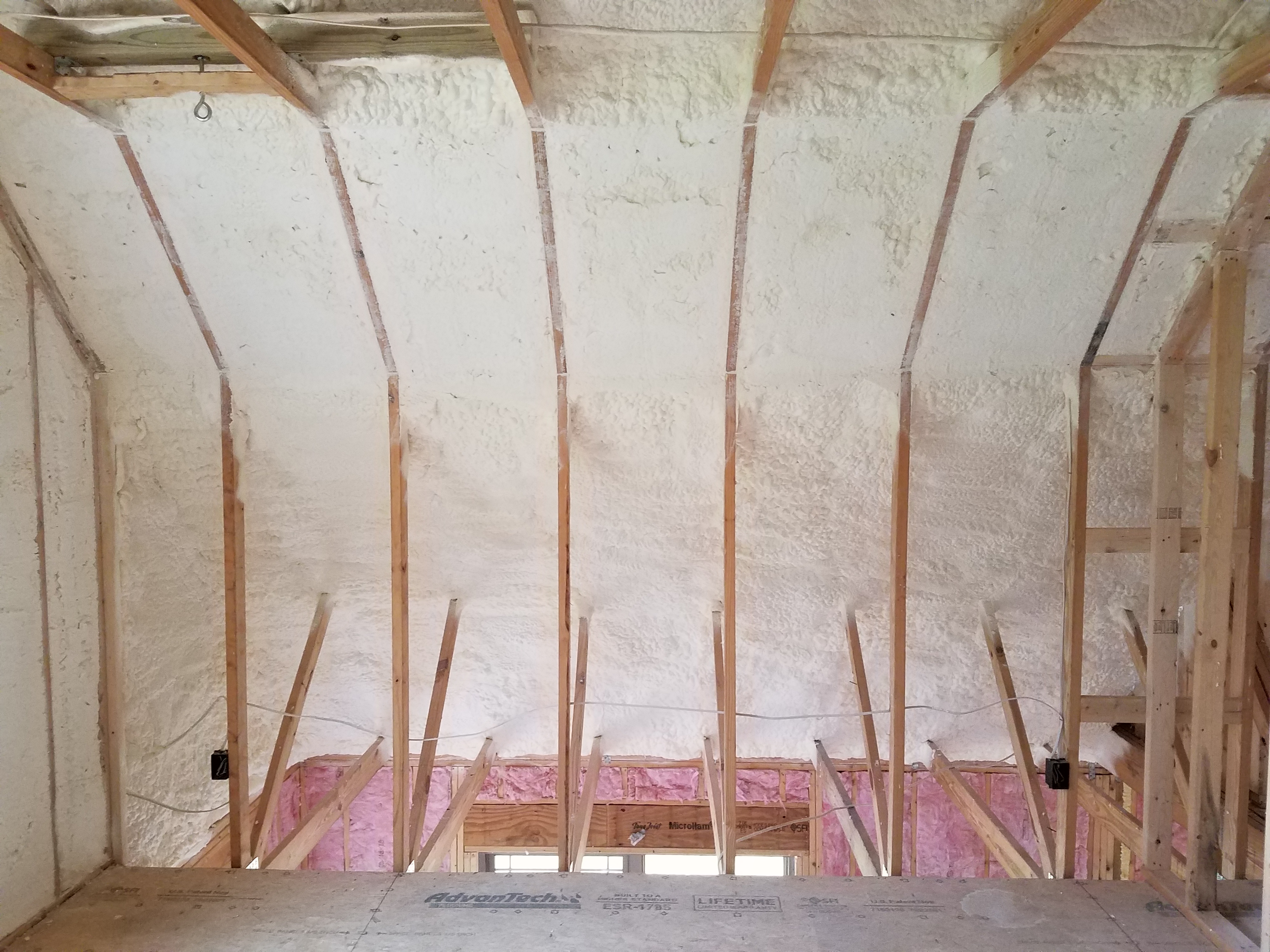
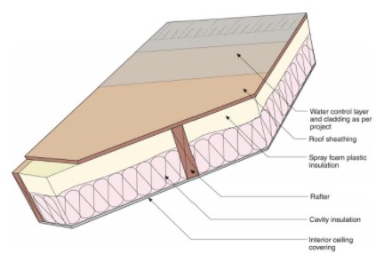
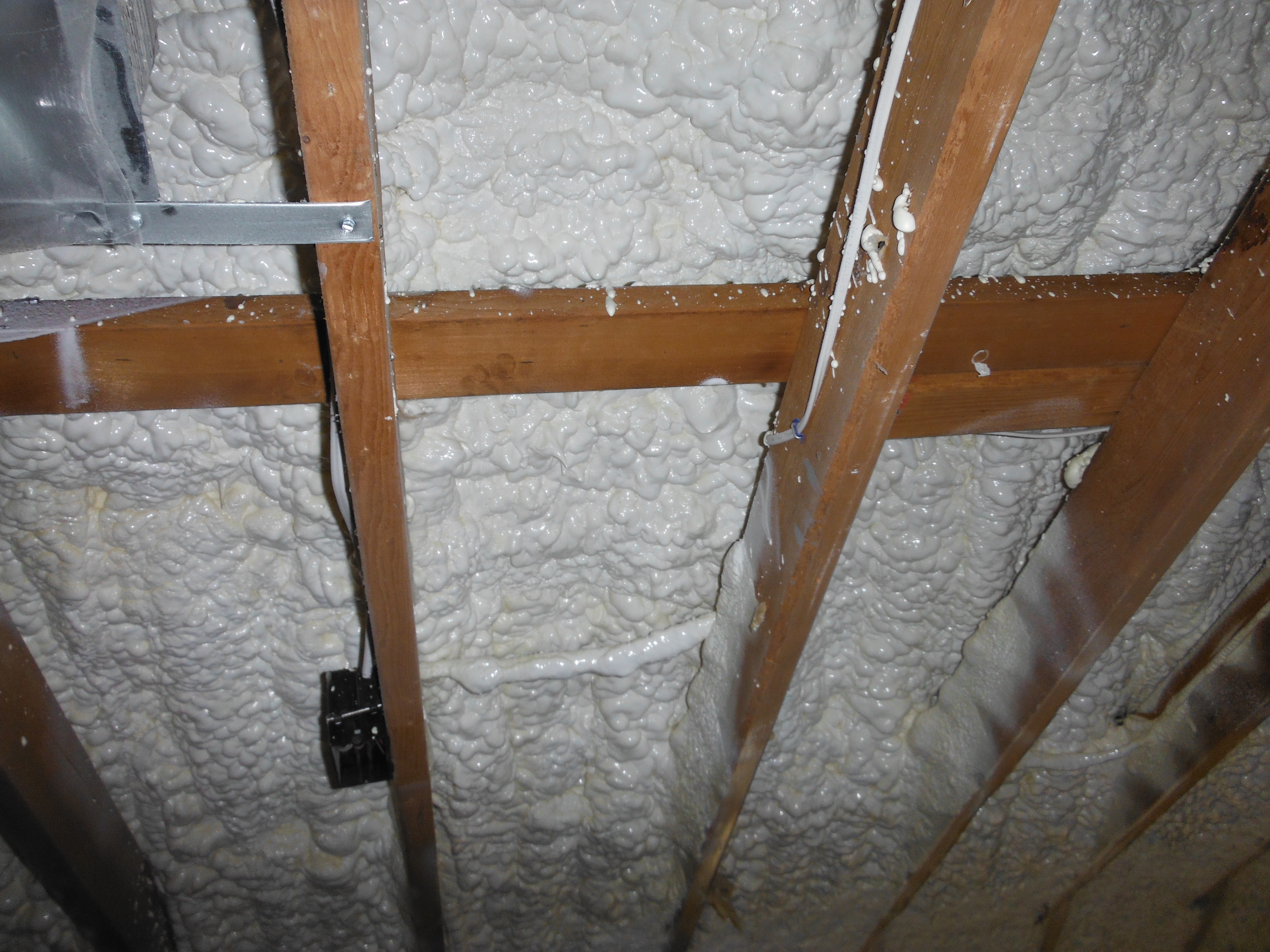
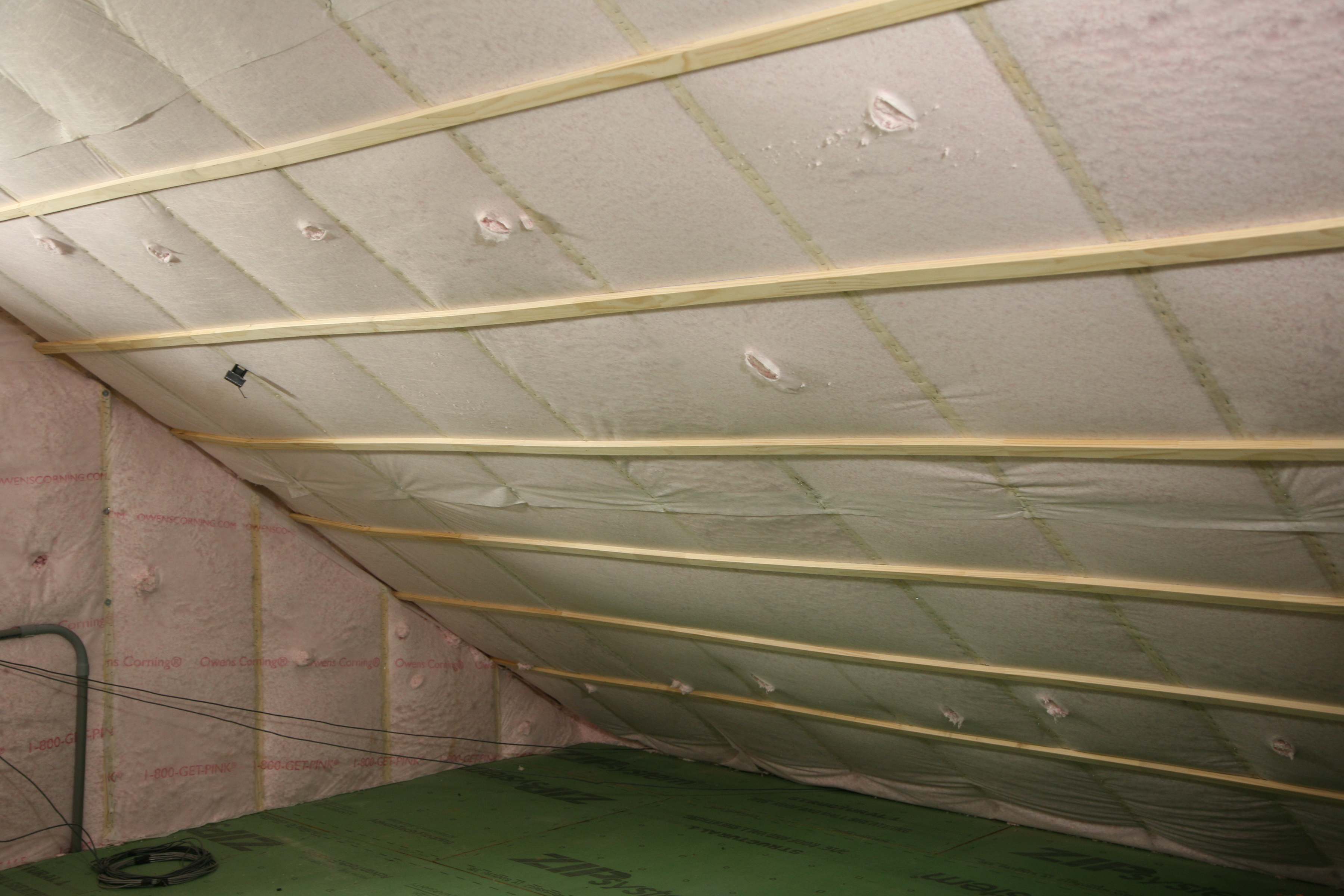
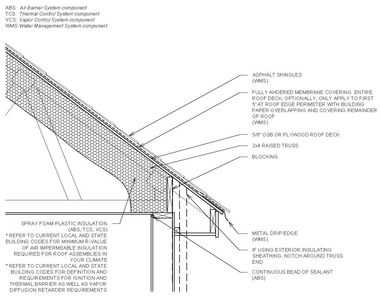
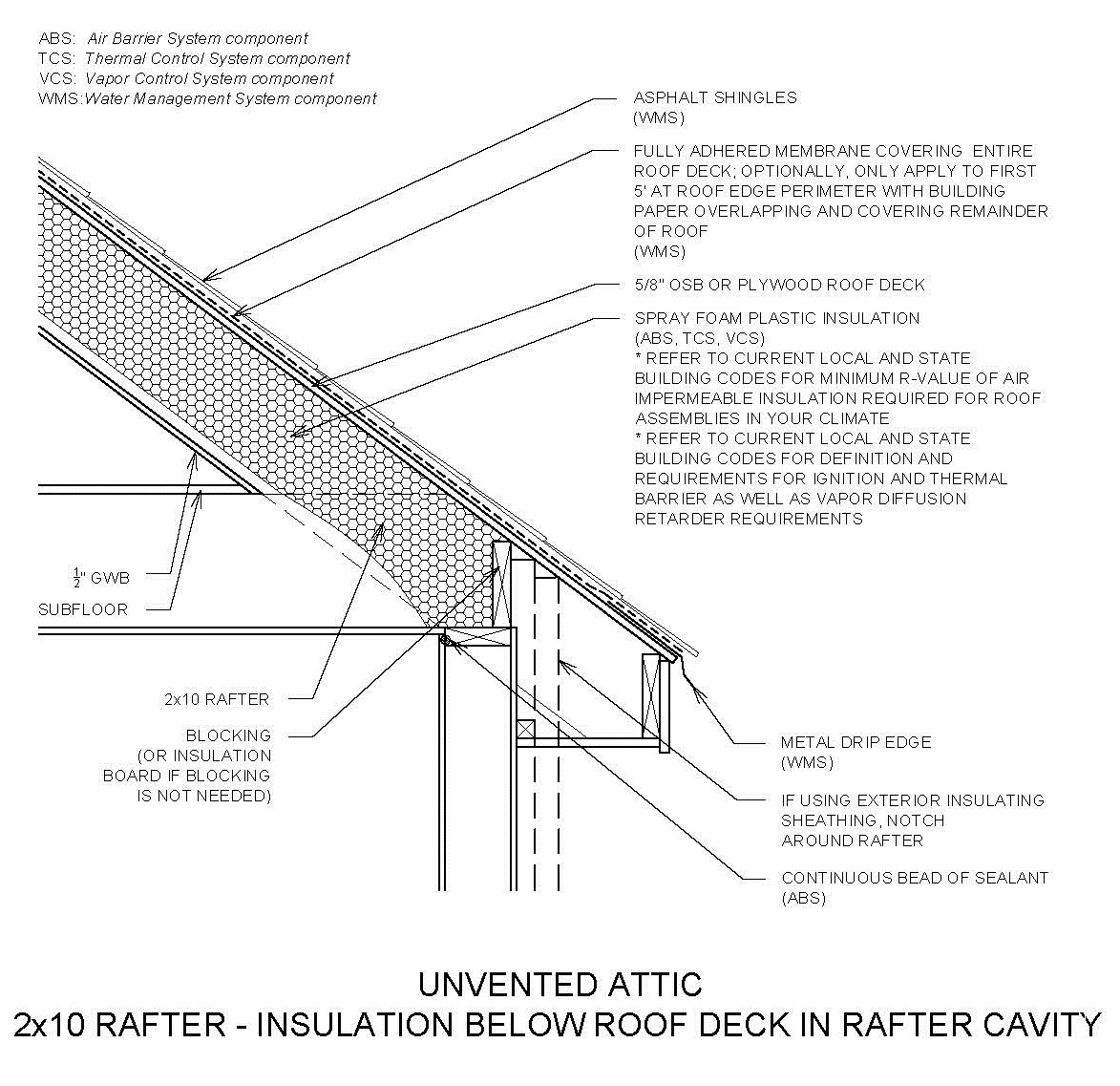
    Figure 2 shows an unvented cathedralized attic design with air-impermeable expanding spray foam insulation installed at the underside of the roof deck.

    Unvented cathedralized attic detail.
    Figure 2. Unvented cathedralized attic detail, with air-impermeable spray foam insulation installed to the underside of the roof deck.


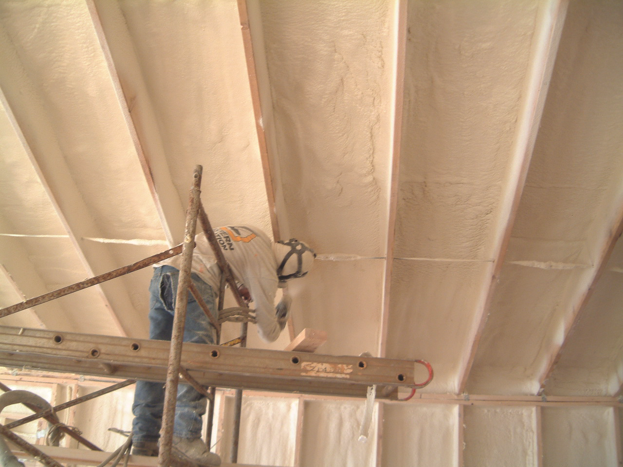
    How to Install Spray Foam under the Roof Deck in a Cathedral Ceiling

    *  It is recommended that the spray foam insulation is installed by a licensed professional applicator.

    1. Refer to the current state and local building codes for the minimum R-value of air-impermeable insulation required for the roof assemblies in your climate.
    2. Inspect the roof assembly to ensure it has proper drainage protection above the roof deck.
    3. Measure the moisture content of the wood prior to applying spray foam insulation to ensure it has dried to the levels recommended by the spray foam manufacturer.
    4. Ensure the weather conditions and temperatures for installing the insulation are as recommended by the spray foam manufacturer.
    5. Clean the surfaces of the roof sheathing and structural members so they are clear of any debris or dust to ensure proper adhesion of the spray foam.
    6. Cover any mechanical and electrical equipment and wiring prior to applying the insulation.
    7. Provide proper ventilation in the work area during application.
    8. It is recommended to hire a licensed professional applicator for the spray foam installation.
    9. Visually inspect the insulation installation.
    10. Refer to the current state and local building codes for definition and requirements for the ignition and thermal barrier as well as vapor diffusion retarder requirements.
    11. Install cavity insulation.

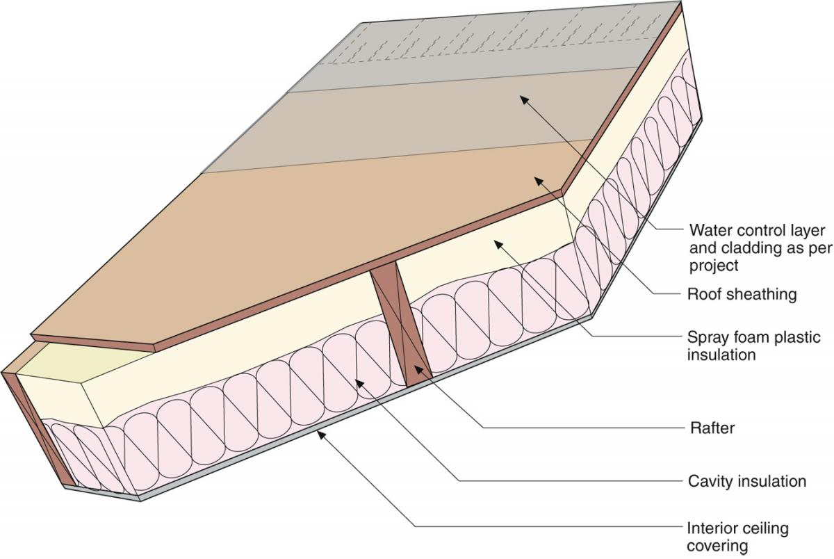
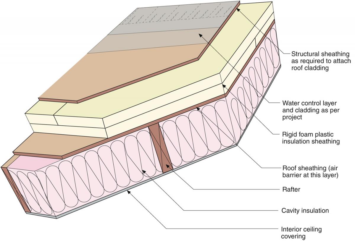
    Air-Impermeable Insulation Installed Over the Roof Sheathing with a Cathedral Ceiling

    Figure 3 shows an unvented cathedralized attic design with air-impermeable insulating sheathing installed over the roof deck. A structural nail base would typically be required over the rigid foam for a roof cladding such as asphalt shingles. To meet durability goals in most applications, the airtightness must be provided by a continuous membrane—preferably adhered to the top surface of the structural roof deck and under rigid insulation that provides condensation control. 

    Unvented cathedralized attic detail, with air-impermeable insulating sheathing installed over the roof deck.
    Figure 3. Unvented cathedralized attic detail, with air-impermeable insulating sheathing installed over the roof deck.


    How to Install Insulating Sheathing over the Roof Deck with a Cathedral Ceiling

    1. Refer to the current state and local building codes for the minimum R-value of air-impermeable insulation required for the roof assemblies in your climate.
    2. Install a weather-resistive, air-impermeable roofing underlayment (i.e., fully adhered membrane), properly lapped, and ensure it is integrated with the wall weather resistive barrier (e.g., house wrap). 
    3. Inspect roof deck weather resistive barrier for any leaks or any inconsistencies.
    4. Install insulating sheathing in multiple layers with joints offset in both directions and taped.
    5. Install OSB/plywood over the insulating sheathing to serve as a nailbase.
    6. Install proper roofing underlayment and roof cladding according to manufacturer’s instruction.
    7. Install cavity insulation.

    How to Install Ducts in an Unvented Attic

    When installing HVAC equipment in an insulated conditioned attic, good HVAC design principles still apply:

    1. Design a compact, duct layout with short, straight ducts runs. Seal and test ductwork for air leakage.
    2. Install a balanced ventilation system such as a heat recovery ventilator or central fan-integrated ventilation with a fresh air intake and timered exhaust. (For more information, see Whole-Building Delivered Ventilation.)
    3. Do not install low-efficiency heating systems that draw their combustion air from the attic. Instead install direct-vent sealed-combustion furnaces or heat pumps. (For more information, see Combustion Furnaces, Traditional Split Heat Pumps)
    Success
    Ensuring Success

    Regular inspections should be conducted between major points in construction to check on the integrity of the water, air, thermal and vapor control layers of the roof. Monitor the moisture content of the roof sheathing, when possible, during the construction process.  Take measurements before the installation of the air-impermeable insulation to ensure that the roof deck is dry enough to be covered.  This is especially true for spray foam installed to the underside of the roof deck. Ensure correct ambient temperature for spray foam application and ensure that framing and underside of roof decking has been swept clean of dust and debris before installing spray foam.

    When installing HVAC equipment in an insulated, conditioned attic, design a compact duct layout with short, straight ducts runs. Seal and test ductwork for air leakage. Install a balanced ventilation system. Install high-efficiency direct-vent sealed-combustion furnaces or heat pumps.

    Climate
    Climate

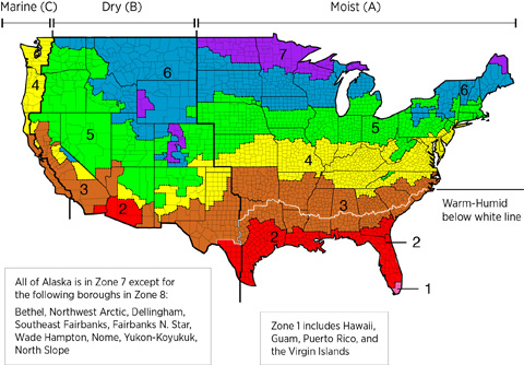
    The International Energy Conservation Code (IECC) requires minimum levels of air-impermeable insulation for each climate zone.

    The map in Figure 1 shows the climate zones for states that have adopted energy codes equivalent to the International Energy Conservation Code (IECC) 2009, 12, 15, and 18. The map in Figure 2 shows the climate zones for states that have adopted energy codes equivalent to the IECC 2021. Climate zone-specific requirements specified in the IECC are shown in the Compliance Tab of this guide. 

    Climate Zone Map from IECC 2009, 12, 15, and 18.
    Figure 1. Climate Zone Map from IECC 2009, 12, 15, and 18. (Source: 2012 IECC)


    Climate Zone Map from IECC 2021.
    Figure 2. Climate Zone Map from IECC 2021. (Source: 2021 IECC)


    Cold Climates

     In high snow load climates it is preferable to keep heating equipment out of the attic, because heat transfer from the ducts or heating equipment to the roof deck of the attic can warm the deck, causing snow melt that could lead to ice dam formation. If HVAC equipment is installed in attics in cold climates, installers must be especially careful to thoroughly air seal and insulate the equipment.  

    See Lstiburek 2014 for additional discussion about insulating attics at the roof line in very cold climates with either closed-cell spray foam on the underside of the roof deck or rigid foam on top of the roof deck separated from the cladding by a ventilating air gap.

    Training
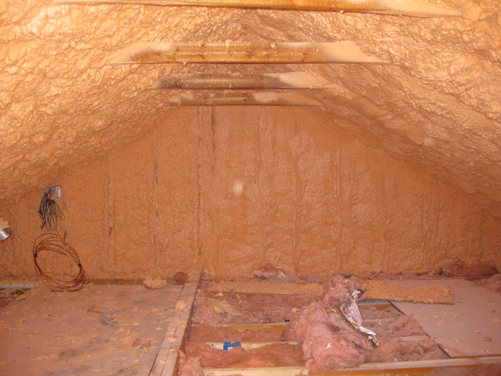
    Right and Wrong Images
    Image
    Right - Closed-cell spray foam is installed as a skim coat to provide air tightness to an exterior wall cavity before installing batt or blown cavity insulation.
    Right - Closed-cell spray foam is installed as a skim coat to provide air tightness to an exterior wall cavity before installing batt or blown cavity insulation.
    Image
    Right - The underside of the attic roof deck is insulated with open-cell spray foam to provide an insulated space for HVAC equipment.
    Right - The underside of the attic roof deck is insulated with open-cell spray foam to provide an insulated space for HVAC equipment.
    Image
    Right - A technician applies a thin layer of closed-cell foam to air seal an unvented attic assembly before filling the ceiling joists with batt or blown insulation.
    Right - A technician applies a thin layer of closed-cell foam to air seal an unvented attic assembly before filling the ceiling joists with batt or blown insulation.
    Image
    Right – Spray foam insulates the unvented attic.
    Right – Spray foam insulates the unvented attic.
    Image
    Spray foam insulation was installed on the underside of the roof deck and on gable end attic walls to create an unvented attic
    Spray foam insulation was installed on the underside of the roof deck and on gable end attic walls to create an unvented attic
    Image
    Air-Impermeable Insulation for Condensation Control in Unvented Attics, per IRC Table 806.5.
    Air-Impermeable Insulation for Condensation Control in Unvented Attics, per IRC Table 806.5.
    Image
    Detail of an unvented cathedralized attic showing air-impermeable spray foam insulation plus batt insulation installed on the underside of the roof deck.
    Detail of an unvented cathedralized attic showing air-impermeable spray foam insulation plus batt insulation installed on the underside of the roof deck.
    Image
    The builders sprayed the underside of the roof assembly with 6 inches of open-cell spray foam to create an unvented, R-48 insulated attic.
    The builders sprayed the underside of the roof assembly with 6 inches of open-cell spray foam to create an unvented, R-48 insulated attic.
    Image
    Underneath the roof sheathing and two exterior layers of rigid foam, the builder stapled netting to the underside of the rafters and filled the roof cavities of the unvented attic with blown-in fiberglass insulation.
    Underneath the roof sheathing and two exterior layers of rigid foam, the builder stapled netting to the underside of the rafters and filled the roof cavities of the unvented attic with blown-in fiberglass insulation.
    Image
    The unvented attic is insulated along the underside of the roof deck with 7 inches (R-49) of closed-cell spray foam, providing vaulted ceilings and a conditioned knee wall space for ducting.
    The unvented attic is insulated along the underside of the roof deck with 7 inches (R-49) of closed-cell spray foam, providing vaulted ceilings and a conditioned knee wall space for ducting.
    Image
    Right – Spray foam insulates the unvented attic.
    Right – Spray foam insulates the unvented attic.
    Image
    Right – Spray foam fills the roof joist cavities of this vaulted, unvented attic.
    Right – Spray foam fills the roof joist cavities of this vaulted, unvented attic.
    Image
    Right – R-23 of blown fiberglass fills the walls and unvented vaulted attic cavities of this marine-climate home while an additional R-20 (4-inches) of graphite-enhanced expanded polystyrene is installed above the roof sheathing.
    Right – R-23 of blown fiberglass fills the walls and unvented vaulted attic cavities of this marine-climate home while an additional R-20 (4-inches) of graphite-enhanced expanded polystyrene is installed above the roof sheathing.
    Presentations
    Videos
    CAD
    CAD Files
    2x4 Raised Truss - Insulation Below Roof Deck CAD
    2x4 Raised Truss - Insulation Below Roof Deck CAD
    Download: DWG PDF
    2x10 Rafter - Insulation Above Roof Deck and In Rafter Cavity CAD
    2x10 Rafter - Insulation Above Roof Deck and In Rafter Cavity CAD
    Download: DWG PDF
    2x10 Rafter - Insulation Below Roof Deck In Rafter Cavity CAD
    2x10 Rafter - Insulation Below Roof Deck In Rafter Cavity CAD
    Download: DWG PDF
    2x12 Rafter - Insulation Above Roof Deck and In Rafter Cavity CAD
    2x12 Rafter - Insulation Above Roof Deck and In Rafter Cavity CAD
    Download: DWG PDF
    2x12 Rafter - Insulation Below Roof Deck In Rafter Cavity CAD
    2x12 Rafter - Insulation Below Roof Deck In Rafter Cavity CAD
    Download: DWG PDF
    Compliance

    Compliance

    The Compliance tab contains both program and code information. Code language is excerpted and summarized below. For exact code language, refer to the applicable code, which may require purchase from the publisher. While we continually update our database, links may have changed since posting. Please contact our webmaster if you find broken links.


    ENERGY STAR Single-Family New Homes, Version 3/3.1 (Rev. 11)

    ENERGY STAR Single-Family New Homes requires that ceiling, wall, floor, and slab insulation levels meet or exceed those specified in the 2009 International Energy Conservation Code (IECC) with some alternatives and exceptions, and achieve Grade 1 installation per RESNET Standards (see 2009 and 2012 IECC Code Level Insulation – ENERGY STAR Requirements and Insulation Installation (RESNET Grade 1). If the state or local residential building energy code requires higher insulation levels than those specified in the 2009 IECC, you must meet or exceed the locally mandated requirements. Visit the U.S. DOE Building Energy Codes Program to see what code has been adopted in each state.


    DOE Zero Energy Ready Home (Revision 07)

    Exhibit 1 Mandatory Requirements.
    Exhibit 1, Item 1) Certified under the ENERGY STAR Qualified Homes Program or the ENERGY STAR Multifamily New Construction Program.
    Exhibit 2, Item 2) Ceiling, wall, floor, and slab insulation shall meet or exceed 2015 IECC levels and achieve Grade 1 installation, per RESNET standards. See the guide 2015 IECC Code Level Insulation – DOE Zero Energy Ready Home Requirements for more details.
    Exhibit 1, Item 3) Duct distribution systems located within the home’s thermal and air barrier boundary or an optimized location to achieve comparable performance.

    Footnote 14) Exceptions and alternative compliance paths to locating 100% of forced-air ducts in home’s thermal and air barrier boundary are:

    1. Up to 10’ of total duct length is permitted to be outside of the home’s thermal and air barrier boundary.
    2. Ducts are located in an unvented attic, regardless of whether this space is conditioned with a supply register.
    3. Ducts are located in a vented attic with all of the following characteristics: [​Note that in either of these designs the HVAC equipment must still be located within the home’s thermal and air barrier boundary.
      1. In Moist climates (Zones 1A, 2A, 3A, 4A, 5A, 6A and 7A per 2015 IECC Figure R301.1) and Marine climates (all “C” Zones per 2015 IECC Figure R301.1), minimum R-8 duct insulation with an additional minimum 1.5” of closed-cell spray foam insulation encapsulating the ducts; duct leakage to outdoors ≤ 3 CFM25 per 100 ft2 of conditioned floor area (in addition to meeting total duct leakage requirements from Section 4.1 of the ENERGY STAR HVAC Rater checklist); and ductwork buried under at least 2” of blown-in insulation.
      2. In Dry climates (all “B” Zones per 2015 IECC Figure R301.1), minimum R-8 duct insulation; duct leakage to outdoors ≤ 3 CFM25 per 100 ft2 of conditioned floor area (in addition to meeting total duct leakage requirements from Section 4.1 of the ENERGY STAR HVAC Rater checklist); and ductwork buried under at least 3.5” of blown-in insulation.
    4. Systems which meet the criteria for “Ducts Located in Conditioned Space” as defined by the 2018 IECC Section R403.3.7
    5. Jump ducts which do not directly deliver conditioned air from the HVAC unit may be located in attics if all joints, including boot-to-drywall, are fully air sealed with mastic or foam, and the jump duct is fully buried under the attic insulation.
    6. Ducts are located within an unvented crawl space.
    7. Ducts are located in a basement which is within the home’s thermal boundary.
    8. Ductless HVAC system is used.


    2009-2021 IECC and IRC Insulation Requirements Table

    The minimum insulation requirements for ceilings, walls, floors, and foundations in new homes, as listed in the 2009, 2012, 2015, 2018, and 2021 IECC and IRC, can be found in this table


    2009, 2012, 2015, 2018, and 2021 International Energy Conservation Code (IECC)

    Total ceiling insulation values are shown by climate zone in Table R402.1.1 (R402.1.2 in 2015 and 2018  IECC); excerpts are shown in Table 1 below.

    2009 IECC Sec. 402.2.1 and 2012, 2015, and 2018 IECC Sec. R402.2.1 note that where the table specifies R-38, R-30 will be sufficient if the full height of R-30 extends uncompressed over the wall top plate at the eaves. Similarly R-38 will be sufficient where R-49 is required if a full thickness of R-38 extends over the top plates. This is extended in the 2021 IECC: R-49 will be sufficient for an R-60 requirement if a full thickness of R-49 extends over the top plates. Sec R402.2.2 notes that in parts of the ceiling where the attic design does not allow space to install more than R-30 of insulation, R-30 will suffice; however, this exception is limited to no more than 500 square feet of total ceiling area.

    Retrofit:  2009, 2012, 2015, 2018,  and 2021 IECC

    Section R101.4.3 (in 2009 and 2012). Additions, alterations, renovations, or repairs shall conform to the provisions of this code, without requiring the unaltered portions of the existing building to comply with this code. (See code for additional requirements and exceptions.)

    Chapter 5 (in 2015, 2018, 2021). The provisions of this chapter shall control the alteration, repair, addition, and change of occupancy of existing buildings and structures.


    2009, 2012, 20152018, and  2021 International Residential Code (IRC)

    The 2009 and 2012 IRC Section R202 defines vapor retarders class information.  A vapor retarder is defined as “a measure of the ability of a material or assembly to limit the amount of moisture that passes through that material or assembly.”  Vapor retarder classes are defined by the IRC using the desiccant method with Procedure A of ASTM E96. These classes are:

    Class I: 0.1 perm or less
    Class II: 0.1 perm to 1.0 perm
    Class III: 1 perm to 10 perms

    The IRC has had information on unvented attics for several editions.  The 2012 IRC Section R806 contains the following requirements, with slight modifications from the 2009 edition, with the most notable addition being identification of vapor retarders by class in R806.5 items 2 and 4. In IRC 2018, see Section R806.5 for additional information about the vapor permeability of the insulation used.

    R806.5 Unvented attic and unvented enclosed rafter assemblies.  Unvented attic assemblies and unvented enclosed rafter assemblies are permitted if all the following conditions are met:

    1. The unvented attic space is completely contained within the building thermal envelope.
    2. No interior Class I vapor retarders are installed on the ceiling side (attic floor) of the unvented attic assembly or on the ceiling side of the unvented enclosed rafter assembly.
    3. Where wood shingles or shakes are used, a minimum ¼” (6mm) vented air space separates the shingles or shakes and the roofing underlayment above the structural sheathing.
    4. In Climate Zones 5, 6, 7, and 8, any air-impermeable insulation shall be a Class II vapor retarder or shall have a Class II vapor retarder coating or covering in direct contact with the underside of the insulation. [Note, the 2012 IRC says “or be coated with a Class III vapor retarder.” “Class III” is a typo that has been corrected to Class II in the 2015 I codes (BSC personal communication 6-27-14).]
    5. Meet one of the following conditions, depending on the air permeability of the insulation directly under the structural roof sheathing.
      1. Air-impermeable insulation only.  Insulation shall be applied in direct contact with the underside of the structural roof sheathing.
      2. Air-permeable insulation only.  In addition to the air-permeable insulation installed directly below the structural sheathing, rigid board or sheet insulation shall be installed directly above the structural roof sheathing as specified in Table R806.5 for condensation control.
      3. Air-impermeable and air-permeable insulation.  The air-impermeable insulation shall be applied in direct contact with the underside of the structural roof sheathing as specified in Table R806.5 for condensation control.  The air-permeable insulation shall be installed directly under the air-impermeable insulation.
      4. Where preformed insulation board is used as the air impermeable insulation layer, it shall be sealed at the perimeter of each individual sheet interior surface to form a continuous layer.
    1. Up to 10’ of total duct length is permitted to be outside of the home’s thermal and air barrier boundary.
    2. Ducts are located in an unvented attic, regardless of whether this space is conditioned with a supply register.
    3. Ducts are located in a vented attic with all of the following characteristics: [​Note that in either of these designs the HVAC equipment must still be located within the home’s thermal and air barrier boundary.

    Wording in the 2018 IRC differs for #5:

    5. Insulation shall comply with Item 5.3 and either item 5.1 or 5.2:

    5.1. Item 5.1.1, 5.1.2, 5.1.3, or 5.1.4 shall be met, depending on the air permeability of the insulation directly under the structural roof sheathing.

    5.1.1. Where only air-impermeable insulation is provided, it shall be applied in direct contact with the underside of the structural roof sheathing.

    5.1.2. Where air-permeable insulation is installed directly below the structural sheathing, rigid board or sheet insulation shall be installed directly above the structural roof sheathing in accordance with the R-values in Table R806.5 for condensation control.

    5.1.3. Where both air-impermeable and air-permeable insulation are provided, the air-impermeable insulation shall be applied in direct contact with the underside of the structural roof sheathing in accordance with item 5.1.1 and shall be in accordance with the R-values in Table R806.5 for condensation control. The air-permeable insulation shall be installed directly under the air-impermeable insulation.

    5.1.4. Alternatively, sufficient rigid board or sheet insulation shall be installed directly above the structural roof sheathing to maintain the monthly average temperature of the underside of the structural roof sheathing above 45°F (7°C). For calculation purposes, an interior air temperature of 68°F (20°C) is assumed and the exterior air temperature is assumed to be the monthly average outside air temperature of the three coldest months. 

    5.2. In Climate Zones 1, 2 and 3, air-permeable insulation installed in unvented attics shall meet the following requirements:

    5.2.1 An approved vapor diffusion port shall be installed not more than 12 inches (305 mm) from the highest point of the roof, measured vertically from the highest point of the roof to the lower edge of the port.

    5.2.2. The port area shall be greater than or equal to 1:600 of the ceiling area. Where there are multiple ports in the attic, the sum of the port areas shall be greater than or equal to the area requirement.

    5.2.3 The vapor-permeable membrane in the vapor diffusion port shall have a vapor permeance rating of greater than or equal to 20 perms when tested in accordance with Procedure A of ASTM E96.

    5.2.4. The vapor diffusion port shall serve as an air barrier between the attic and the exterior of the building.

    5.2.5. The vapor diffusion port shall protect the attic against the entrance of rain and snow.

    5.2.6. Framing members and blocking shall not block the free flow of water vapor to the port. Not less than a 2-inch (51 mm) space shall be provided between any blocking and the roof sheathing. Air-permeable insulation shall be permitted within that space.

    5.2.7. The roof slope shall be greater than or equal to 3:12 (vertical/horizontal).

    5.2.8 Where only air-permable insulation is used, it shall be installed directly below the structural roof sheathing.

    5.2.9. Air-impermeable insulation, if any, shall be directly above or below the structural roof sheathing and is not required to meet the R-value in Table 806.5. Where direclty below the structural roof sheathing, there shall be no  space between the air-impermeable insulation and air-permeable insulation.

    5.2.10. The air shall be supplied at a flow rate greater than or equal to 50 cfm (23.6 L/s)per 1,000 square feet (93 m2) of ceiling. The air shall be supplied from ductwork providing supply air to the occupiable space when the conditioning system is operating. Alternatively, the air shall be supplied by a supply fan when the condition system is operating.

    5.3. Where pre-formed insulation board is used as the air-impermeable insulation layer, it shall be sealed at the perimeter of each individual sheet interior surface to form a continuous layer.

    The IRC for Climate Zones 1, 2, 3, or 4 requires that a Class I vapor control layer not be installed on the interior side of the assembly.  This is to prevent inward-driven moisture from being trapped in the wall assembly.  Installing a low-permeance vapor control layer on the interior in a cooling dominated climate can quickly deteriorate the assembly. 

    Table N1102.1.1 of the 2012 IRC (N1102.1.2 in 2015 and 2018 IRC) lists the thermal insulation requirements for each assembly. A summary of the requirements combining Table R806.5 and Table N1102.1.1 from the 2009, 12, 15, and 18 IRC editions is shown in Table 2. This table shows the total amount of insulation required in unvented attics and unvented enclosed roof framing assemblies and the minimum amount of that insulation that should be impermeable, based on climate zone.

    Air-Impermeable Insulation for Condensation Control in Unvented Attics, per IRC Table 806.5
    Table 2. Air-Impermeable Insulation for Condensation Control in Unvented Attics, per IRC Table 806.5


    In cold climates it is important to note the ratio of vapor impermeable to vapor permeable R-values.  For cold climates, the air impermeable insulation is maintained at 50% or more of the total R-value of the roof system. This is for condensation control.  When building high-R value roof systems Building Science Corporation recommends that this ratio be maintained or exceeded.  If an R-80 cathedral ceiling or cathedralized attic is to be constructed in a cold climate, it is recommended that a minimum of R-40 (50%) be air impermeable insulation installed and layered according to Section R806.5 of the 2012 IRC.

    Retrofit:  2009, 2012, 2015, 2018,  and 2021 IRC

    Section R102.7.1 Additions, alterations, or repairs. Additions, alterations, renovations, or repairs shall conform to the provisions of this code, without requiring the unaltered portions of the existing building to comply with the requirements of this code, unless otherwise stated. (See code for additional requirements and exceptions.)

    Appendix J regulates the repair, renovation, alteration, and reconstruction of existing buildings and is intended to encourage their continued safe use.

    Retrofit
    Existing Homes

    SCOPE

    Convert a vented attic to an unvented attic and insulate using one of the methods described in the Description tab or similar.

    • Close and seal all attic vents, including roof deck and soffit vents.
    • If installing insulation above the decking, remove existing roof tiles or shingles and replace weather-resistant barrier if needed.
    • Install above- or below-deck insulation.

    See the U.S. Department of Energy Standard Work Specifications for additional guidance on preparing the roof deck for spray foam, insulating the underside of the roof deck with spray foam insulation, using polyurethane spray foam, and air sealing a cathedralized attic.

    For guidance on working in attics, see the Pre-Retrofit Assessment of Attics, Ceilings, and Roofs.

    DESCRIPTION

    Convert a vented attic to an unvented attic and insulate using one of the methods described in the Description tab or similar. Prior to installing insulation, close off and seal all attic vents, including roof deck and soffit vents. If installing insulation above the decking, remove existing roof tiles or shingles and replace weather-resistant barrier if needed. Follow the installation guidance provided in the Description tab and as recommended by the manufacturer. Prior to installation, verify installation method with roofing contractor and local code officials.

    More

    More Info.

    Access to some references may require purchase from the publisher. While we continually update our database, links may have changed since posting. Please contact our webmaster if you find broken links.

    Case Studies
    References and Resources*
    Author(s)
    Building Science Corporation
    Organization(s)
    BSC
    Publication Date
    Description
    Report discussing how to create livable space in the attic that meets IRC code requirements by either creating a ventilated roof assembly, or and unvented attic assembly.
    Author(s)
    Lstiburek
    Organization(s)
    Building Science Corporation,
    BSC
    Publication Date
    Description
    BSD-102 report providing guidance about whether to construct a vented or unvented attic based on hygro-thermal zone.
    Author(s)
    Holladay
    Organization(s)
    Green Building Advisor
    Publication Date
    Description
    Information sheet presenting the correct methods for building an insulated cathedral ceiling.
    Author(s)
    Kohta
    Organization(s)
    Building Science Corporation
    Publication Date
    Description
    Document summarizing the various papers on unvented conditioned cathedralized attics found on BSC's website.
    Author(s)
    Schumacher
    Organization(s)
    Building Science Corporation,
    BSC
    Publication Date
    Description
    Report reviewing unvented roof assemblies, such as conditioned attics and unvented cathedral ceilings that are becoming common in North American construction.
    Author(s)
    Coble Brian
    Organization(s)
    Home Energy Magazine
    Publication Date
    Description
    Article describing how insulating and air sealing unfinished attic spaces can lead to reduced energy bills in some homes.
    Author(s)
    Lstiburek
    Organization(s)
    BSC
    Publication Date
    Description
    Article describing the difference between conditioned or unvented attics and unconditioned or vented attics.
    Author(s)
    Lstiburek
    Organization(s)
    BSC
    Publication Date
    Description
    Article describing issues with condensation in unvented attics insulated with open-cell spray foam.
    Author(s)
    Yost
    Organization(s)
    Journal of Light Construction
    Publication Date
    Description
    Article describing the building science implications of insulating vented or unvented attics.
    Author(s)
    Yost
    Organization(s)
    Journal of Light Construction
    Publication Date
    Description
    Article describing the research into insulating vented versus unvented attics.
    Author(s)
    Lstiburek
    Organization(s)
    Building Science Corporation,
    BSC
    Publication Date
    Description
    Article describing methods for insulating and air sealing vented and unvented roofs in various climates zones.
    *For non-dated media, such as websites, the date listed is the date accessed.
    Contributors to this Guide

    The following authors and organizations contributed to the content in this Guide.

    Sales
    Building Science Measures
    Building Science-to-Sales Translator

    High-R Attic Insulation = High-Efficiency or Ultra-Efficient Attic Insulation

    Image(s)
    Technical Description

    There are two levels of attic insulation: high-efficiency insulation, which meets the 2015 International Energy Conservation Code, and ultra-efficient insulation, which is 25% more efficient than this national code. Using high-efficiency and ultra-efficient insulation along with professional installation (e.g., no gaps, voids, compression, or misalignment with air barriers;  complete air barriers; and minimal thermal bridging) creates conditioned spaces that require very little heating  and cooling, along with even comfort and quiet throughout the house.

    High-Efficiency or Ultra-Efficient Attic Insulation
    Sales Message

    High-efficiency attic insulation helps provide added thermal protection. What this means to you is less wasted energy along with enhanced comfort and quiet. Knowing there is one opportunity to optimize performance during construction, wouldn’t you agree it’s a great opportunity to meet or exceed future codes?

    Last Updated

    Mobile Field Kit

    The Building America Field Kit allows you to save items to your profile for review or use on-site.

    Sign Up  or  Log In

    Did you find this information helpful?

    If you have questions and/or would like a reply to this feedback, please include your e-mail address in the message.
    This question is for testing whether or not you are a human visitor and to prevent automated spam submissions.