
Building Cavities Not Used as Supply or Return Ducts

    Scope
    Scope Images
    Image
    Building cavities not used as supply or return ducts unless they meet Items 3.2, 3.3, 4.1, and 4.2 of this Checklist
    Scope

    Do not use building cavities as part of a forced air supply or return system.

    See the Compliance Tab for related codes and standards requirements, and criteria to meet national programs such as DOE’s Zero Energy Ready Home programENERGY STAR Single-Family New Homes, and Indoor airPLUS.

    Description
    Description

    Nearly all codes restrict the use of cavity spaces as supply ducts. However, it has been common practice to use cavity spaces as return air pathways. Building cavities used as return air plenums are probably the biggest duct leakage culprits we have in the HVAC industry today.

    Still commonly used is the panned floor joist. Using floor joists as return ducts by panning can cause leakage because negative pressure in the cavity will draw air from the outside into the cavity through the construction joints of the rim area at the end of the joist cavity.

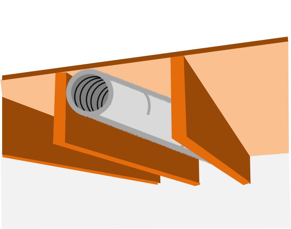
    Figure 1 shows a floor joist cavity used as a return air duct by nailing a sheet good, such as gypsum board, sheet metal, foil insulation, or OSB to the bottom of the floor joists. There are manufacturers advertising “insulating” sheet good products to aid in this practice; however, using panned floor joists as an HVAC air pathway is highly discouraged because air leakage will be very difficult, if not impossible, to prevent.

    Some builders create pan joists by attaching a solid sheet good to the bottom of a floor joist to create a return air pathway
    Figure 1. Some builders create pan joists by attaching a solid sheet good to the bottom of a floor joist to create a return air pathway. Pan joists should not be used as return air pathways because they cannot be air sealed properly (Source: Courtesy of CalcsPlus). 

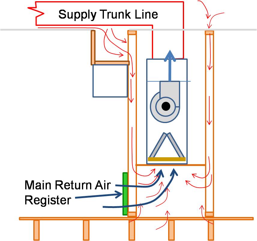
    Cavities (or interstitial spaces) within walls are also sometimes used as supply or return air pathways. These cavities often connect inside air with outside air from an attic or crawlspace. It is very difficult to make such cavity spaces airtight. When cavity spaces are used as return air pathways or supply air ducts, a few issues will arise. Because cavity spaces are leaky, building pressure imbalances across the building envelope will occur, driving building infiltration. A cavity space used as a return air pathway will pull pollutants into the building from unknown sources. Another issue (less talked about) with using cavity spaces as return air pathways is fire safety. Building materials such as wood products do not meet the flame and smoke spread criteria as do approved duct materials. Using cavities as return or supply ducts is not a fire hazard in itself but will encourage a fire to spread throughout the building. In humid climates, a cavity space used as a return air pathway will pull humid air into the cavity space, possibly encouraging mold or rotting of building materials.

    Other common framing cavities used as return air pathways or plenums are air handler platforms, open floor truss cavities, and dropped ceilings.
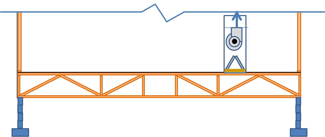
    Open floor trusses used as return air plenums can draw air from any place connected to that floor.
    Figure 2. Open floor trusses used as return air plenums can draw air from any place connected to that floor (Source: Courtesy of CalcsPlus).


    Air handler platforms used as return air plenums can draw air from vented attics and crawlspaces through other connected framing cavities
    Figure 3. Air handler platforms used as return air plenums can draw air from vented attics and crawlspaces through other connected framing cavities (Source: Courtesy of CalcsPlus).

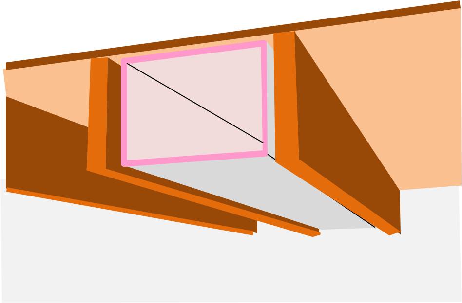
    While none of these spaces make acceptable air pathways on their own, some building cavities such as floor joists can make acceptable duct chases to contain an insulated, air-sealed, metal or flex supply or return duct.


    How to Use Building Cavities as Duct Chases for Supply and Return Pathways:

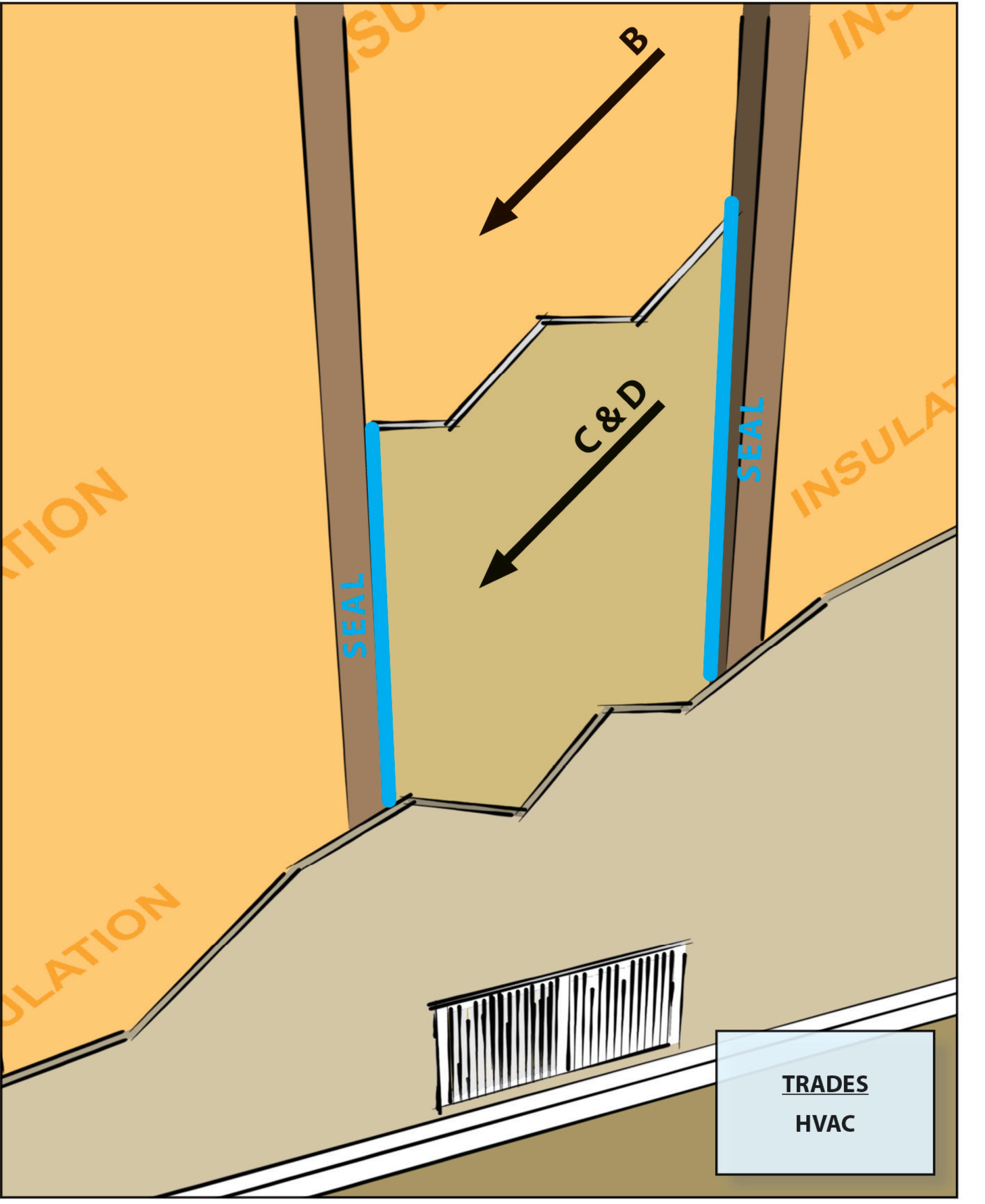
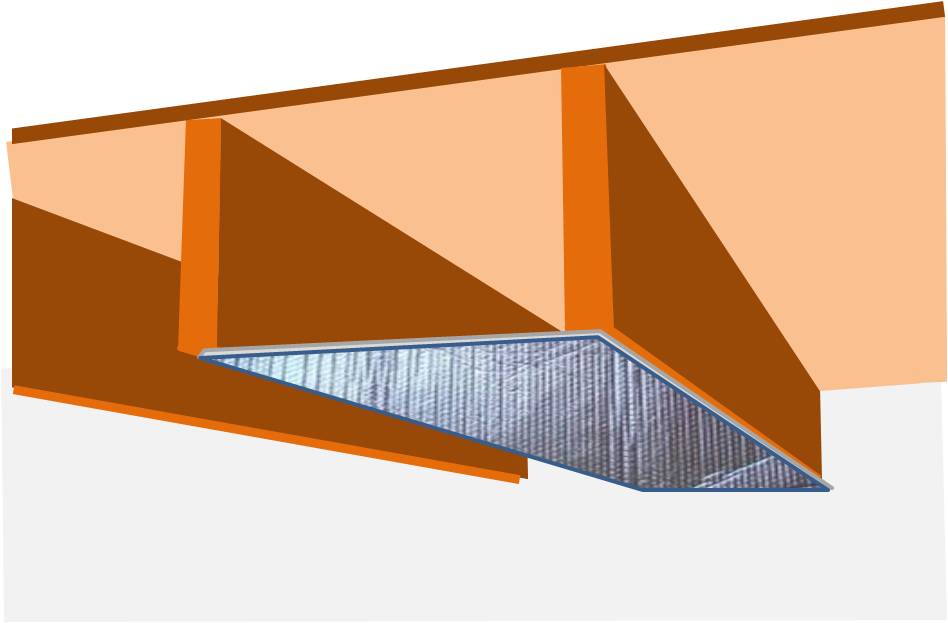
    1. Plan duct layout at the design stage. Indicate floor joist cavities, dropped ceiling soffits, or other building cavities that will be used as duct chases. Calculate required duct sizes using ACCA Manual D (ACCA 2009). Ensure that the cavity spaces are free of obstructions and large enough to hold the duct plus insulation.
    2. Use only approved duct materials such as galvanized steel, aluminum, fiberglass duct board, and flexible duct that meet local code smoke and flame spread criteria.
    3. Make sure that all supply and return duct connections are sealed with mastic or approved tape.
    4. Because ductwork in cavity spaces is likely to be inaccessible, test the duct system for airtightness with a duct blaster test before installing the drywall.
    5. At a minimum, line the air handler platform with duct board and mastic seal the corners.
    floor joist cavity used as duct chase
    Figure 4. Floor joist cavities can make acceptable duct chases for insulated, air-sealed metal, flex, or fiberboard duct (Source: Courtesy of CalcsPlus).
    floor joist cavity used as duct chase
    Figure 5. Floor joist cavities can make acceptable duct chases for insulated, air-sealed metal, flex, or fiberboard duct (Source: Courtesy of CalcsPlus).


    Success
    Ensuring Success

    Use recognized and acceptable duct materials for all HVAC airways. For residential construction, acceptable duct materials include galvanized steel, aluminum, fiberglass duct board, and flexible duct. Consider duct layout in the initial framing design stage. Do not use a building cavity space alone as a supply or return air pathway. For the cavity to serve as a supply or return air pathway, it must contain a sealed, insulated duct made of approved duct materials. Use a duct blaster test to detect duct leakage and to confirm proper air flow at each duct supply outlet.

    Climate
    Climate

    No climate specific information applies. 

    Training
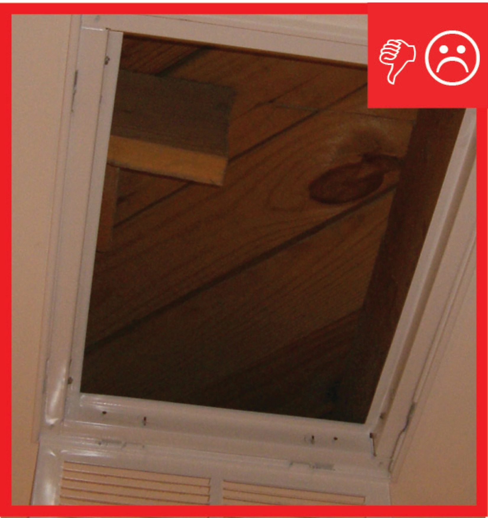
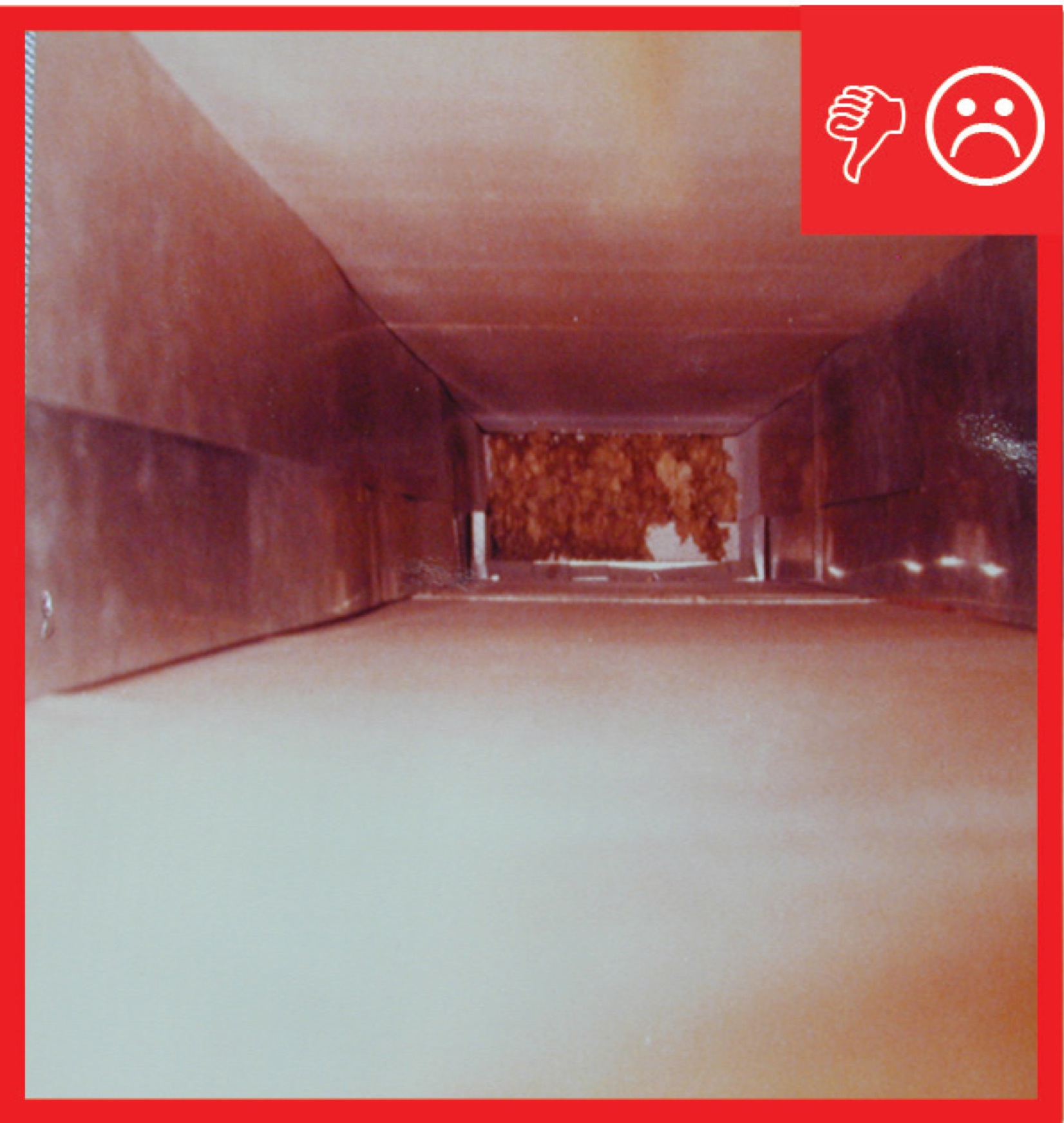
    Right and Wrong Images
    Image
    Cavity used for return is not insulated and is not air sealed, which will pull in air from outside
    Cavity used for return is not insulated and is not air sealed, which will pull in air from outside
    Image
    Cavity was not air sealed
    Cavity was not air sealed
    Compliance

    Compliance

    The Compliance tab contains both program and code information. Code language is excerpted and summarized below. For exact code language, refer to the applicable code, which may require purchase from the publisher. While we continually update our database, links may have changed since posting. Please contact our webmaster if you find broken links.


    ENERGY STAR Single-Family New Homes, Version 3/3.1 (Rev. 11)

    National Program Requirements

    Version 3.0: The ENERGY STAR Reference Design Home is modeled with supply ducts in unconditioned attics with R-8 insulation; all other ducts in unconditioned space modeled with R-6 insulation.

    Version 3.1: All ducts and air handlers are modeled within conditioned space in the ENERGY STAR Reference Design Home.

    The ENERGY STAR Reference Design Home is the set of efficiency features modeled to determine the ENERGY STAR ERI Target for each home pursuing certification. Therefore, while the features below are not mandatory, if they are not used then other measures will be needed to achieve the ENERGY STAR ERI Target. In addition, note that the Mandatory Requirements for All Certified Homes, Exhibit 2, contain additional requirements such as total duct leakage limits, minimum allowed insulation levels, and minimum allowed fenestration performance. Therefore, EPA recommends that partners review the documents in Exhibit 2 prior to selecting measures.

    National Rater Field Checklist

    HVAC System.
    6. Duct Quality Installation - Applies to Heating, Cooling, Ventilation, Exhaust, & Pressure Balancing Ducts, Unless Noted in Footnote.
    6.3 All supply and return ducts in unconditioned space, including connections to trunk ducts, are insulated to ≥ R-6.38
    6.4 Rater-measured total duct leakage meets one of the following two options. Alternative in Footnote 40:39, 40, 41
    6.4.1 Rough-in: The greater of ≤ 4 CFM25 per 100 sq. ft. of CFA or ≤ 40 CFM25, with air handler & all ducts, building cavities used as ducts, & duct boots installed. All duct boots sealed to finished surface, Rater-verified at final.42
    6.4.2 Final: The greater of ≤ 8 CFM25 per 100 sq. ft. of CFA or ≤ 80 CFM25, with the air handler & all ducts, building cavities used as ducts, duct boots, & register grilles atop the finished surface (e.g., drywall, floor) installed.43
    6.5 Rater-measured duct leakage to outdoors the greater of ≤ 4 CFM25 per 100 sq. ft. of CFA or ≤ 40 CFM25.39, 44

    Footnote 38) Item 6.3 does not apply to ducts that are a part of local mechanical exhaust and exhaust-only dwelling unit mechanical ventilation systems. EPA recommends, but does not require, that all metal ductwork not encompassed by Section 6 (e.g., exhaust ducts, duct boots, ducts in conditioned space) also be insulated and that insulation be sealed to duct boots to prevent condensation.

    Footnote 39) Items 6.4 and 6.5 generally apply to the ducts of space heating, space cooling, and dwelling unit mechanical ventilation systems. However, visual inspection is permitted in lieu of testing for a dwelling unit mechanical ventilation system not connected to the space heating or space cooling system, regardless of the number of dwelling units it serves. In such cases, a Rater shall visually verify that all seams and connections are sealed with mastic or metal tape and all duct boots are sealed to floor, wall, or ceiling using caulk, foam, or mastic tape. For duct systems requiring testing, duct leakage shall be determined and documented by a Rater using ANSI / RESNET / ICC Std. 380 including all Addenda and Normative Appendices, with new versions and Addenda implemented according to the schedule defined by the HCO that the home is being certified under. Leakage limits shall be assessed on a per-system, rather than per-home, basis.

    Footnote 40) For a duct system with three or more returns, the total Rater-measured duct leakage is permitted to be the greater of ≤ 6 CFM25 per 100 sq. ft. of CFA or ≤ 60 CFM25 at ‘rough-in’ or the greater of ≤ 12 CFM25 per 100 sq. ft. of CFA or ≤ 120 CFM25 at ‘final’.

    Footnote 41) Note that compliance with Item 6.4.1 or 6.4.2 in conjunction with Section 4a of the National Rater Design Review Checklist automatically achieves Grade I total duct leakage per ANSI / RESNET / ACCA Std. 310.

    Footnote 42) Cabinets (e.g., kitchen, bath, multimedia) or ducts that connect duct boots to toe-kick registers are not required to be in place during the ‘rough-in’ test.

    Footnote 43) Registers atop carpets are permitted to be removed and the face of the duct boot temporarily sealed during testing. In such cases, the Rater shall visually verify that the boot has been durably sealed to the subfloor (e.g., using duct mastic or caulk) to prevent leakage during normal operation.

    Footnote 44) Testing of duct leakage to the outdoors can be waived in accordance with the 2nd or 3rd alternative of ANSI / RESNET / ICC Std. 301, Table 4.2.2 (1), footnote (w). Alternatively, testing of duct leakage to outdoors can be waived in accordance with Section 5.5.2 of ANSI / RESNET / ICC Std. 380 if total duct leakage, at rough-in or final, is ≤ 4 CFM25 per 100 sq. ft. of conditioned floor area or 40 CFM25, whichever is larger. Guidance to assist partners with these alternatives, including modeling inputs, is available at http://www.energystar.gov/newhomesguidance.

    Please see the ENERGY STAR Single-Family New Homes Implementation Timeline for the program version and revision currently applicable in your state.


    DOE Zero Energy Ready Home (Revision 07)

    Exhibit 1 Mandatory Requirements.
    Exhibit 1, Item 1) Certified under the ENERGY STAR Qualified Homes Program or the ENERGY STAR Multifamily New Construction Program.
    Exhibit 1, Item 6) Certified under EPA Indoor airPLUS.


    EPA Indoor airPLUS (Revision 04)

    4.2 Duct System Design and Installation. Do not use building cavities as part of the forced air supply or return systems.


    2009 International Energy Conservation Code (IECC)

    Section 403.2.3 Building cavities (Mandatory). Building framing cavities cannot be used as supply ducts. Section 403.2.1 Insulation (Prescriptive). Supply ducts in attics are insulated to a minimum of R-8. All other ducts in unconditioned spaces or outside the building envelope are insulated to at least R-6.

    2012 IECC

    Section R403.2.3 Building cavities (Mandatory). Building framing cavities cannot be used as supply ducts or plenums. Section R403.2.1 Insulation (Prescriptive). Supply ducts in attics are insulated to a minimum of R-8. All other ducts in unconditioned spaces or outside the building envelope are insulated to at least R-6.

    20152018, and 2021 IECC

    Section R403.3.5 ( R403.3.7 in 2021 IECC) Building cavities (Mandatory).  Building framing cavities cannot be used as supply ducts or plenums. 

    Section 403.3.1 Insulation (Prescriptive).  Supply and return ducts in attics insulated to at least R-8 if 3 inches in diameter or more or R-6 if less than 3 inches.  All other ducts insulated to at least R-6 if 3 inches in diameter or more and R-4.2 (R-6 in 2021 IECC) if less than 3 inches. 

    Retrofit:  2009, 2012, 2015, 2018,  and 2021 IECC

    Section R101.4.3 (in 2009 and 2012). Additions, alterations, renovations, or repairs shall conform to the provisions of this code, without requiring the unaltered portions of the existing building to comply with this code. (See code for additional requirements and exceptions.)

    Chapter 5 (in 2015, 2018, 2021). The provisions of this chapter shall control the alteration, repair, addition, and change of occupancy of existing buildings and structures.


    2009 International Residential Code (IRC)

    Section M1601.1.1 Above-ground duct systems. Stud wall cavities and spaces between solid floor joists cannot be used as supply air plenums.

    2012 IRC

    Section M1601.1.1 Above-ground duct systems. Stud wall cavities and spaces between solid floor joists cannot be used as supply air plenums. Stud wall cavities in building envelope exterior walls cannot be used as air plenums.

    20152018, and 2021 IRC

    Section M1601.1.1 Above-ground duct systems. Stud wall cavities and spaces between solid floor joists cannot be used as supply air plenums. Stud wall cavities in building envelope exterior walls cannot be used as air plenums.

    Section N1103.3.5 Building cavities (Mandatory).  Building framing cavities cannot be used as supply ducts or plenums.  Section N1103.3.1 Insulation (Prescriptive).  Supply and return ducts in attics insulated to at least R-8 if 3 inches in diameter or more or R-6 if less than 3 inches.  All other ducts insulated to at least R-6 if 3 inches in diameter or more and R-4.2 (R-6 in 2021 IRC) if less than 3 inches.

    Retrofit:  2009, 2012, 2015, 2018,  and 2021 IRC

    Section R102.7.1 Additions, alterations, or repairs. Additions, alterations, renovations, or repairs shall conform to the provisions of this code, without requiring the unaltered portions of the existing building to comply with the requirements of this code, unless otherwise stated. (See code for additional requirements and exceptions.)

    Appendix J regulates the repair, renovation, alteration, and reconstruction of existing buildings and is intended to encourage their continued safe use.

    More

    More Info.

    Access to some references may require purchase from the publisher. While we continually update our database, links may have changed since posting. Please contact our webmaster if you find broken links.

    References and Resources*
    Author(s)
    Air Conditioning Contractors of America
    Organization(s)
    ACCA
    Publication Date
    Description
    Standard outlining industry procedure for sizing residential duct systems.
    Author(s)
    Air Diffusion Council
    Organization(s)
    ADC
    Publication Date
    Description
    Standard providing a comprehensive approach to evaluating, selecting, specifying and installing flexible duct in HVAC systems.
    *For non-dated media, such as websites, the date listed is the date accessed.
    Contributors to this Guide

    The following authors and organizations contributed to the content in this Guide.

    Last Updated

    Mobile Field Kit

    The Building America Field Kit allows you to save items to your profile for review or use on-site.

    Sign Up  or  Log In

    Did you find this information helpful?

    If you have questions and/or would like a reply to this feedback, please include your e-mail address in the message.
    This question is for testing whether or not you are a human visitor and to prevent automated spam submissions.