

Scope
Ensure proper air sealing and insulation of attic knee walls.
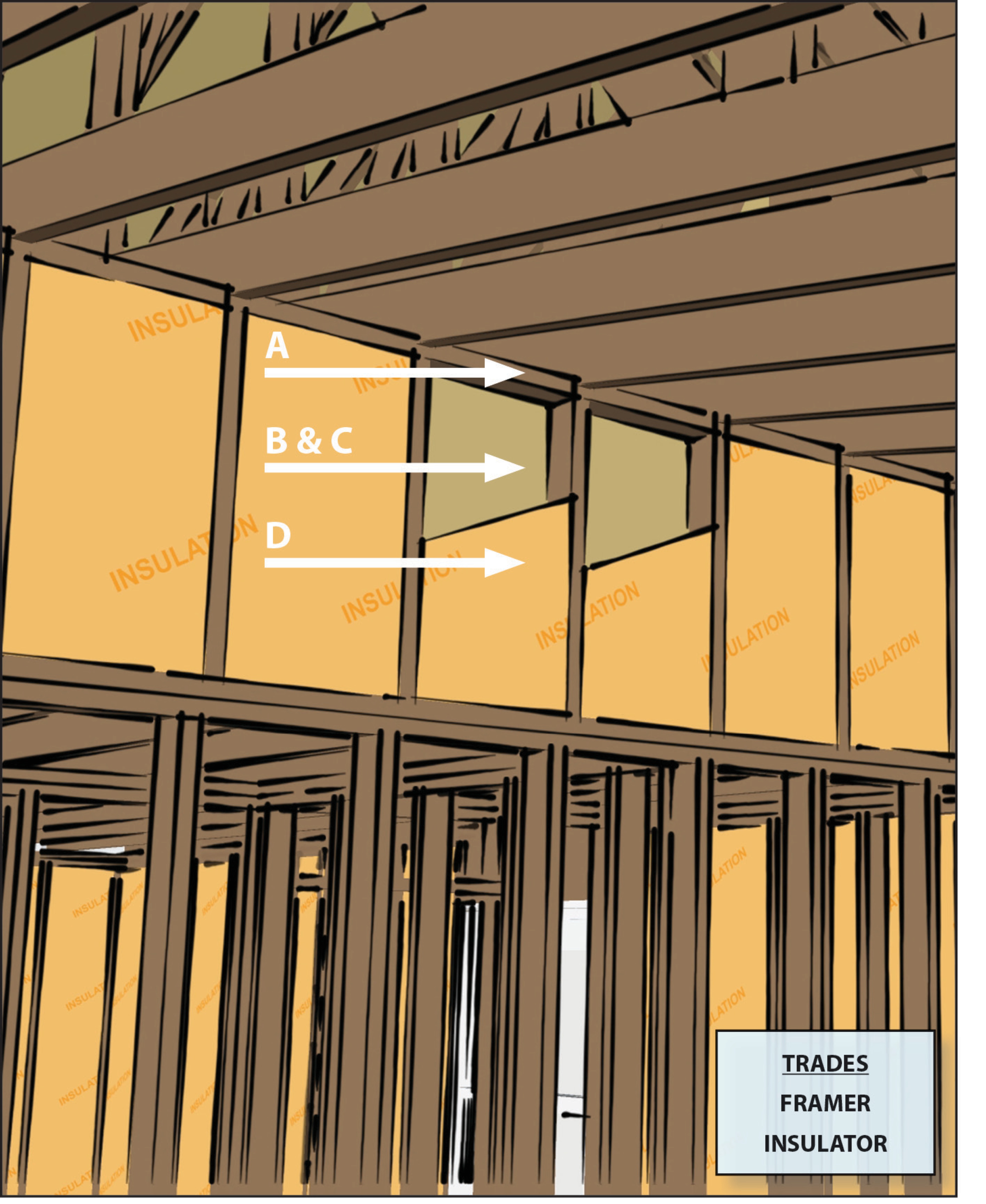
- Install a top and bottom plate or blocking at the top and bottom of all knee wall cavities.
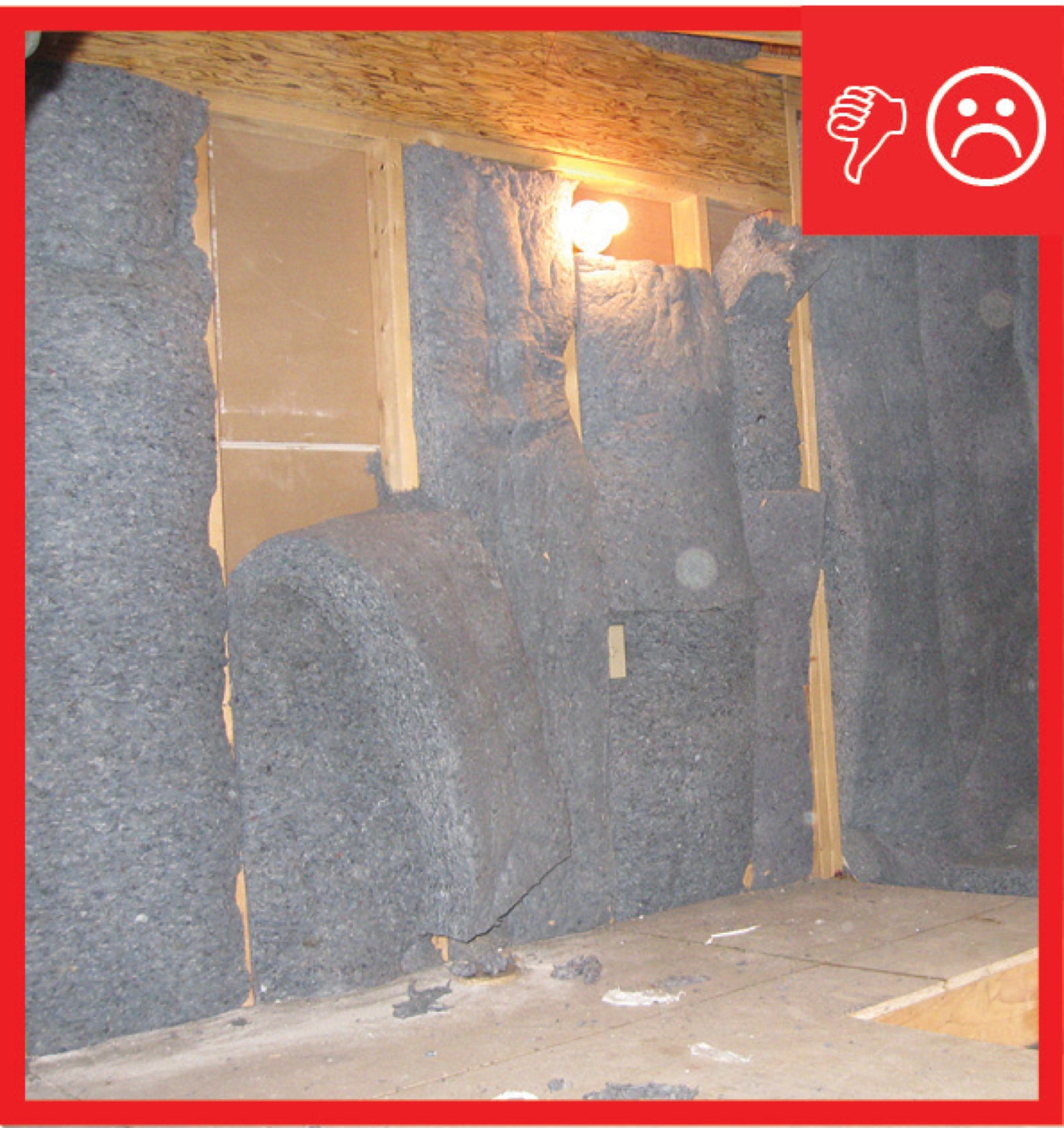
- Install insulation without misalignments, compressions, gaps, or voids in all knee wall cavities.
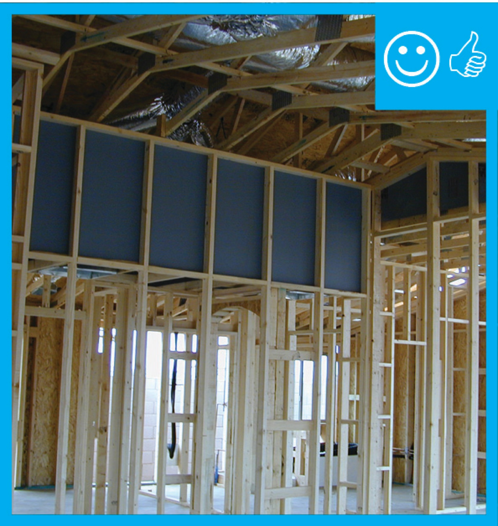
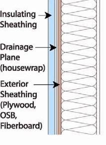
- Install a continuous air barrier on the exterior side of the attic knee wall framing with a rigid air barrier or other supporting material to prevent the knee wall cavity insulation from sagging and to create a continuous thermal barrier. Rigid air barrier material could include rigid foam insulation, drywall, plywood, or OSB, among others.
- Seal all seams, gaps, and holes in the air barrier with caulk or foam.
- If spray foam is used for the wall cavity insulation, the spray foam can serve as the air barrier if it is at least 5.5 inches thick if open-cell or at least 1.5 inches thick if closed-cell.
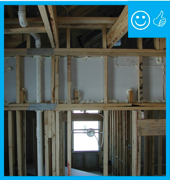
- Install blocking in the joist bays below the knee walls to prevent air flow under the knee walls.
See the Compliance Tab for links to related codes and standards and voluntary federal energy-efficiency program requirements.
Description
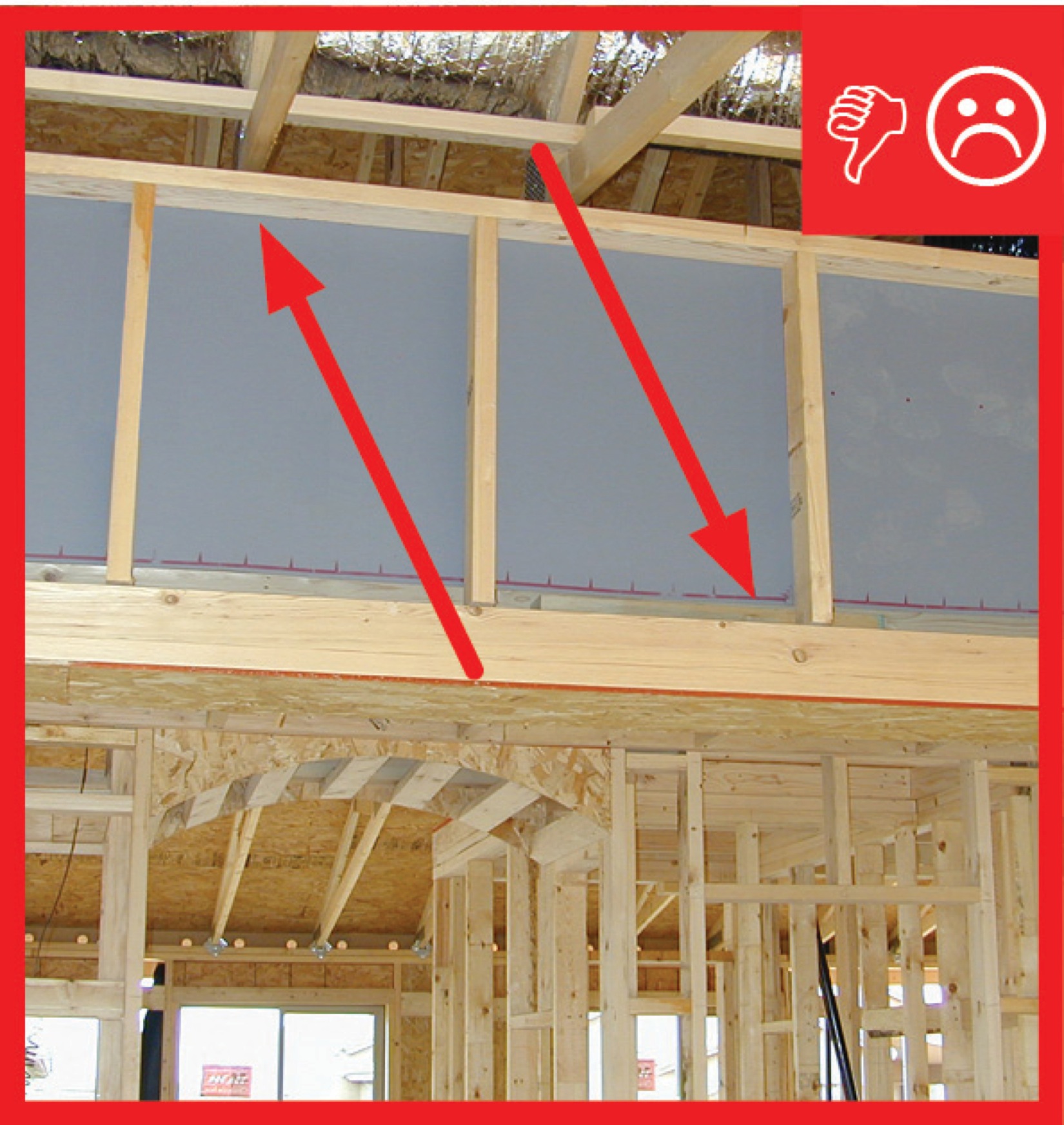
Knee walls, the walls that separate conditioned from unconditioned space in an attic, can be a source of significant air leakage if a continuous air barrier is not provided to prevent unconditioned air from flowing under the knee wall and under the floor boards of the attic room. There are two ways to block this air flow:
1) Install a continuous air barrier on the exterior of the knee wall framing from the top of the knee wall down to the attic floor, including the spaces between the attic floor joists from the bottom of the knee wall to the ceiling deck below, or
2) Install a continuous air barrier along the underside of the attic roofline from the top of the knee wall to the top plate of the home’s exterior wall.
With either method, the air barrier should be installed before installing the attic floor insulation in the unconditioned portion of the attic.
An air barrier is defined as any durable, solid material that blocks air flow between conditioned space and unconditioned space. It should include the air sealing necessary to stop air flow at the edges and seams and adequate support to resist positive and negative pressures without displacement or damage (ENERGY STAR). Air barrier material can include thin sheet goods such as rigid insulation, dry wall, OSB, plywood, or rolled batt insulation that is covered with spray foam. When the kneewall is part of the exterior wall separating conditioned from unconditioned space, it should be insulated to code. This can be accomplished by installing rigid insulation over the wall cavity insulation, or installing a rigid barrier over the wall cavity, air sealing the rigid barrier then applying additional spray foam or batt insulation over the rigid air barrier up to code. These materials may be installed by insulators, framers, or drywallers. This task should be included in the contract for the appropriate trade depending on the workflow at the specific job site.
Air barrier effectiveness is measured at the whole-house level. High-performance branding programs and the 2021 IECC require that builders meet specified infiltration rates at the whole-house level. See the Compliance tab for more details.
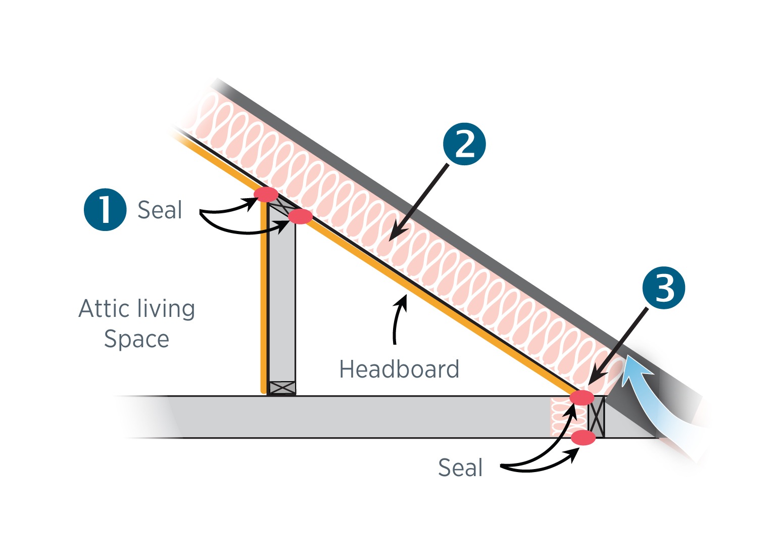
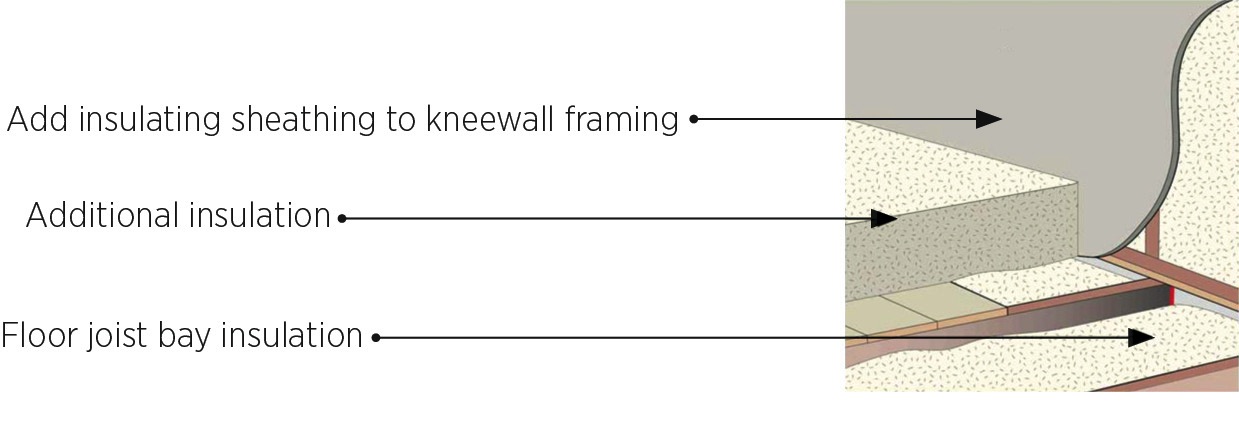
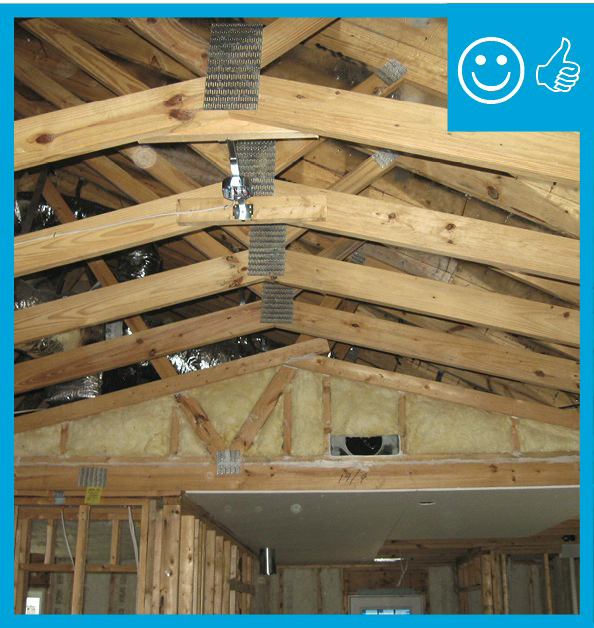
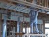
How to Air Seal Knee Walls along the Roofline
Step 1: Insulate and air seal the ceiling of the attic room.
Step 2: Continue the insulation along the roofline to the roof edge (Figure 1).
Step 3: Cover the insulation with a rigid air barrier that is caulked where it meets the plywood floor sheathing, which is extended to the outside wall.
Source
Brochure describing the benefits of air-sealing for homeowners.
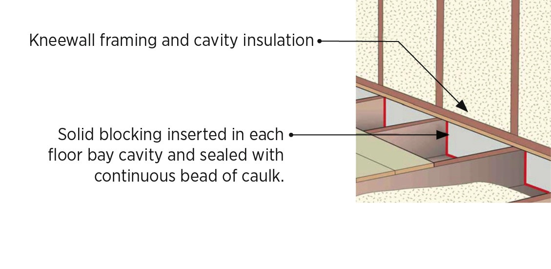
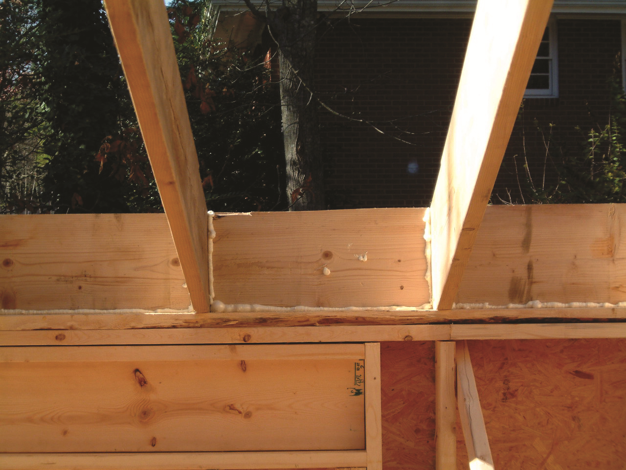
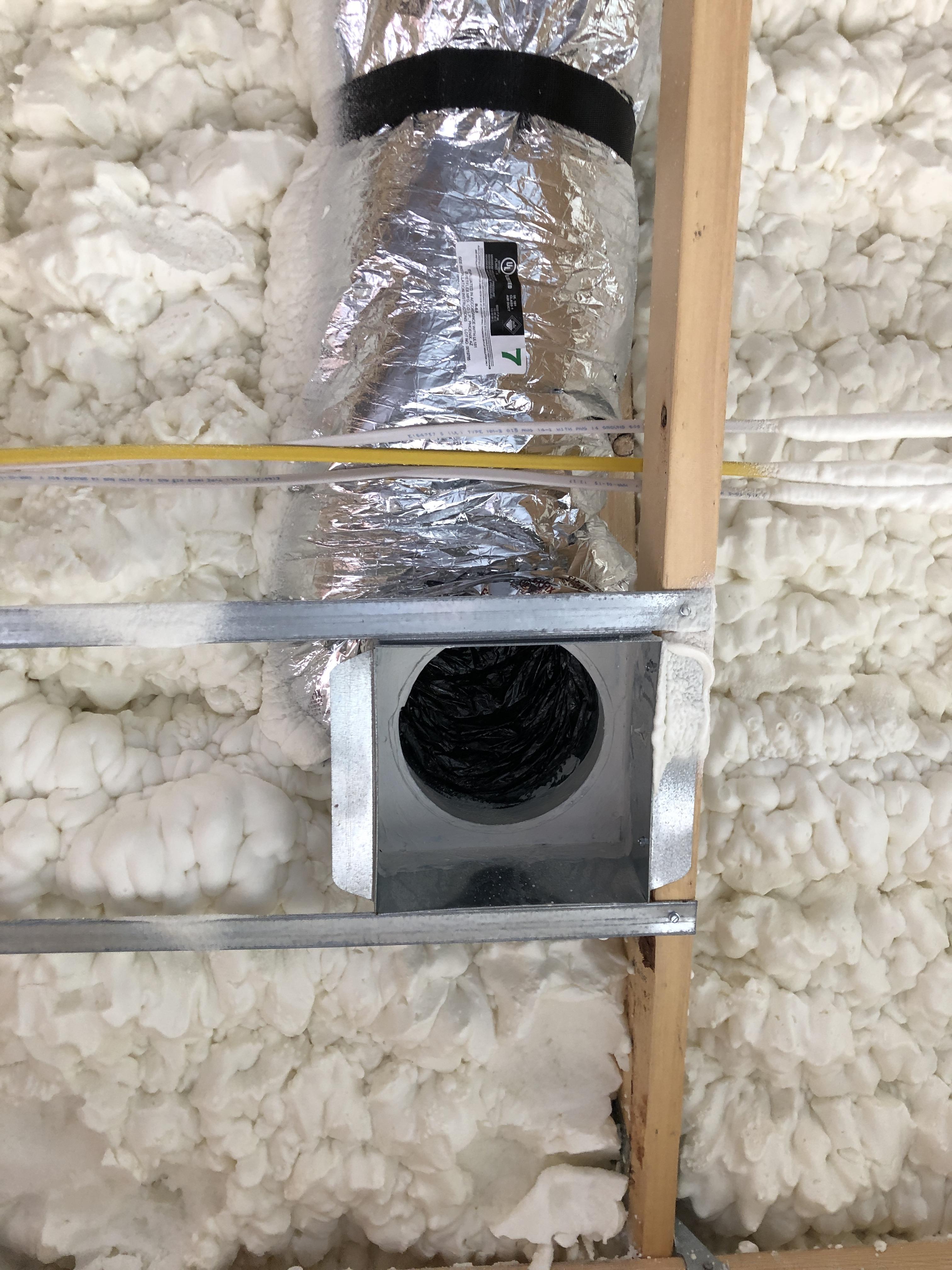
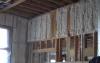
How to Insulate and Air Seal Floor Joist Cavities under Knee Walls
Step 1a: Insert solid wood blocking or a rigid air barrier in the floor joist cavity openings under the knee wall (Figure 2). Seal the edges with a continuous bead of caulk or foam sealant.
Source
-OR-
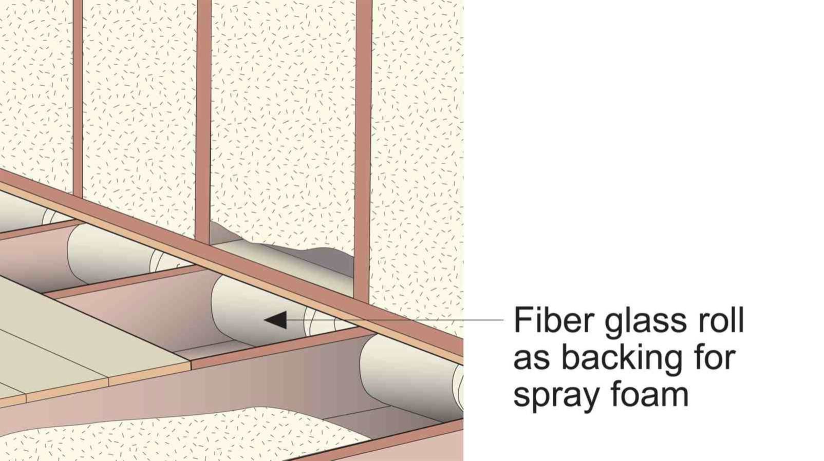
Step 1b: Stuff floor joist cavities with rolls of fiberglass batt and cover them with spray foam to the edges (Figure 3).
Source
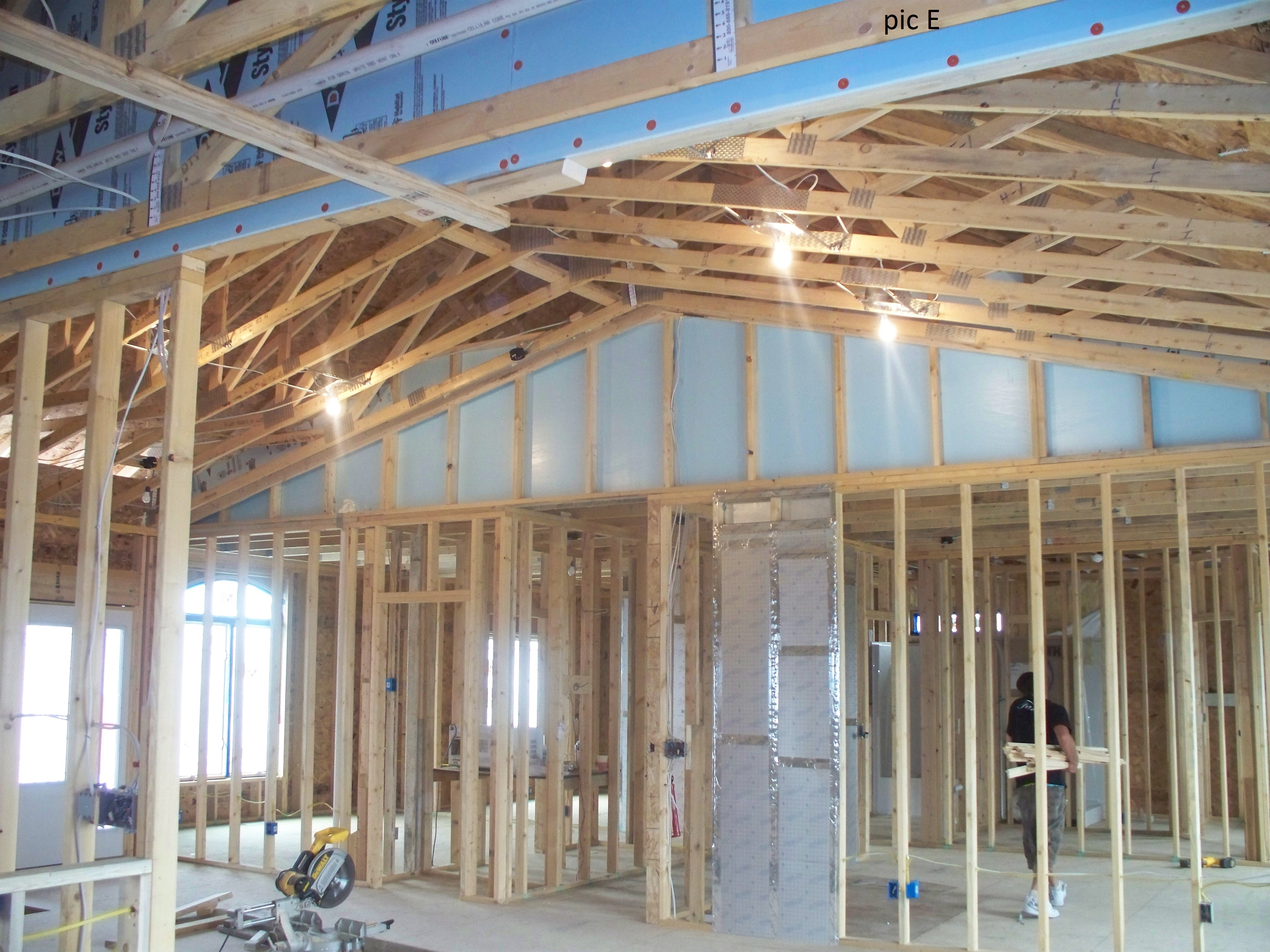
Step 2: Apply caulk to the exterior face of the top plate, bottom plate, and framing at each side of the knee wall. Install a rigid air barrier over the knee wall framing (Figure 4). Seal any seams in the rigid barrier with tape or caulk.
Source
Step 3: Fill the attic floor joist bays with insulation to meet or exceed the code minimum R-value (Figure 4).
Ensuring Success
Blower door testing, conducted as part of whole-house energy performance testing, may help indicate whether air leakage at knee walls has been successfully sealed. An infrared camera and/or visual inspection may also be used to determine locations of air leakage at the knee wall.
Region
Colder climates will increase the potential for and impacts of heat loss and air leakage if the attic knee walls are not properly insulated and air sealed. Heat loss into the attic can warm the underside of the roof deck which can contribute to snow melt and ice dam formation. Significant air leakage from the house into the attic increases the potential for condensation and frost formation in the attic, if warm, humid conditioned air is allowed to escape into a wintertime attic with cold surfaces.
The map in Figure 1 shows the climate zones for states that have adopted energy codes equivalent to the International Energy Conservation Code (IECC) 2009, 12, 15, and 18. The map in Figure 2 shows the climate zones for states that have adopted energy codes equivalent to the IECC 2021. Climate-specific air leakage requirements in the IECC are shown in the Compliance Tab of this guide.

Source
2012 edition of code establishing a baseline for energy efficiency by setting performance standards for the building envelope (defined as the boundary that separates heated/cooled air from unconditioned, outside air), mechanical systems, lighting systems and service water heating systems in homes and commercial businesses.

Source
2021 edition of code establishing a baseline for energy efficiency by setting performance standards for the building envelope (defined as the boundary that separates heated/cooled air from unconditioned, outside air), mechanical systems, lighting systems and service water heating systems in homes and commercial businesses.
Training
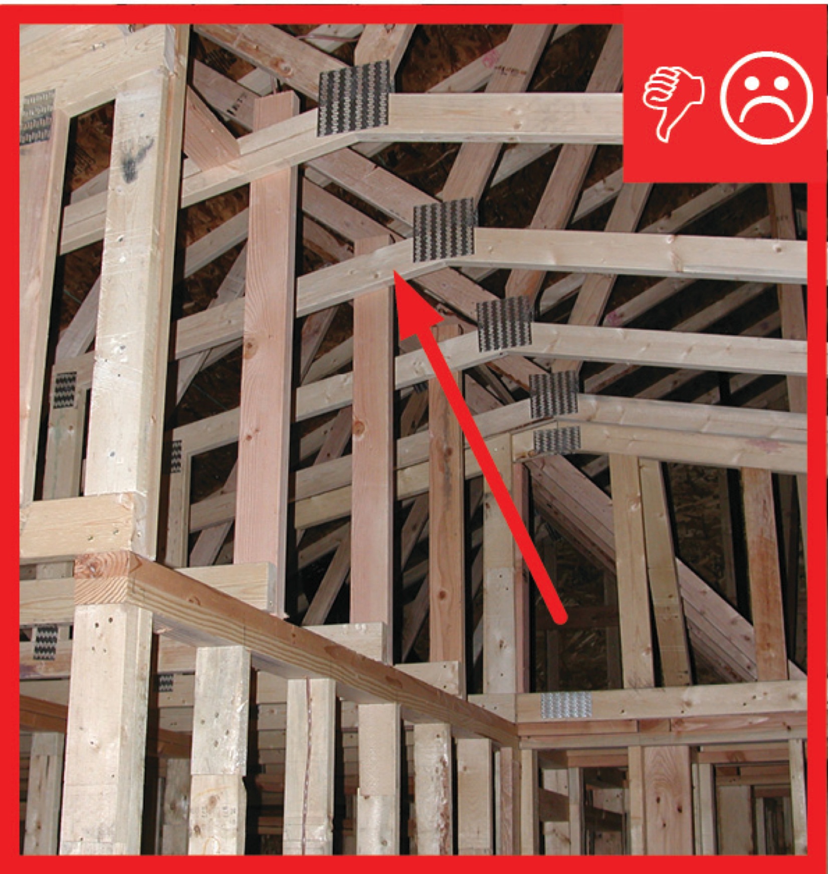
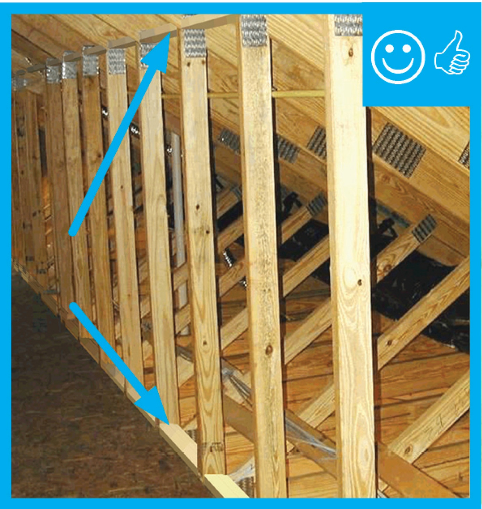
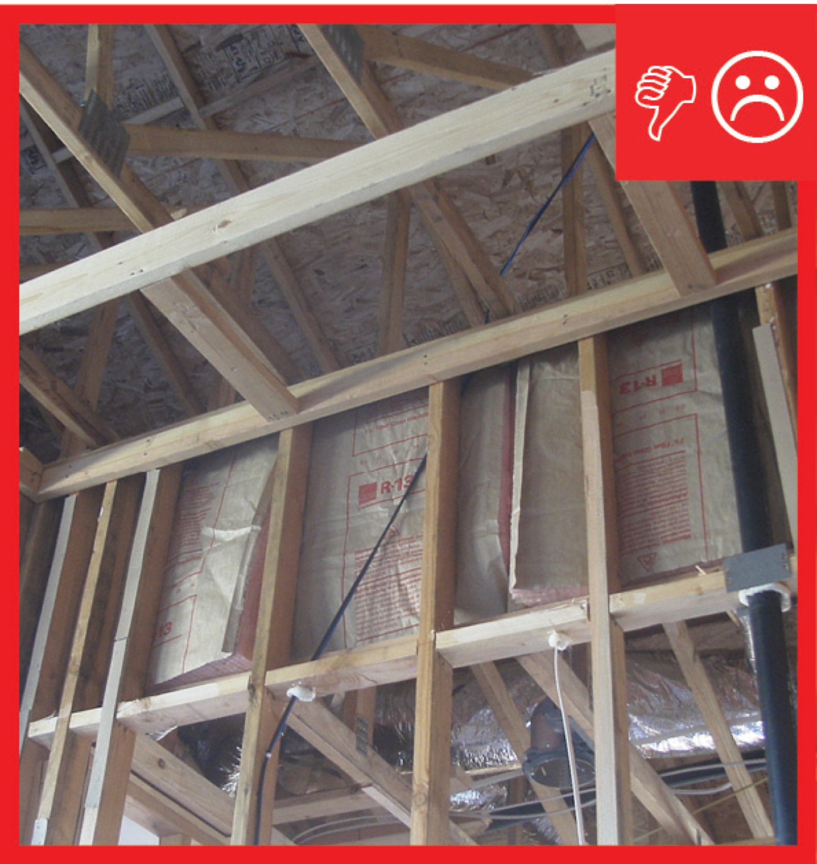
Right and Wrong Images
Source
Guide describing details that serve as a visual reference for each of the line items in the Thermal Enclosure System Rater Checklist.
Source
Guide describing details that serve as a visual reference for each of the line items in the Thermal Enclosure System Rater Checklist.
Source
Guide describing details that serve as a visual reference for each of the line items in the Thermal Enclosure System Rater Checklist.
Source
Guide describing details that serve as a visual reference for each of the line items in the Thermal Enclosure System Rater Checklist.
Source
Guide describing details that serve as a visual reference for each of the line items in the Thermal Enclosure System Rater Checklist.
Source
Guide describing details that serve as a visual reference for each of the line items in the Thermal Enclosure System Rater Checklist.
Source
Guide describing details that serve as a visual reference for each of the line items in the Thermal Enclosure System Rater Checklist.
Source
Guide describing details that serve as a visual reference for each of the line items in the Thermal Enclosure System Rater Checklist.
Source
Article describing how insulating and air sealing unfinished attic spaces can lead to reduced energy bills in some homes.
Source

Source
Research study describing field testing performed in 32 two-story Florida homes to characterize wind washing failures of the house air and thermal boundary.
Source
Videos
CAD Files


Compliance
ENERGY STAR New Homes and Apartments
American Society for Testing Materials (ASTM) E1677-11
Air Barrier Association of America (ABBA) Standards
International Energy Conservation Code (IECC)
International Residential Code (IRC)
American Society of Heating, Refrigeration and Air-Conditioning Engineers (ASHRAE)
More Info
Case Studies
References and Resources
*For non-dated media, such as websites, the date listed is the date accessed.
Contributors to this Guide
The following authors and organizations contributed to the content in this Guide.
Pacific Northwest National Laboratory
Building Science Corporation, lead for the Building Science Consortium (BSC), a DOE Building America Research Team
Sales
Fully Aligned Air Barriers = Whole-House Draft Barrier
Technical Description
A whole-house draft barrier is a continuous layer of air-tight materials that block air leaks. This barrier can be integrated with other materials to also function as a water barrier, thermal barrier, and vapor barrier. For example, rigid foam insulation can be used to block thermal flow as well as air flow when seams are sealed with tape, caulk, adhesives, or liquid-applied sealants. Some rigid foams have an integrated water control layer as well. Additionally, drywall can serve as an interior air barrier when the seams are taped and spackled, and caulk, spray foam, or gaskets are used to seal around wiring, plumbing, and other penetrations. It also serves as the vapor barrier when finished with paint. Insulation should be in full contact with the air barrier layer.
Questions? Comments? Contact our webmaster.