

Scope
Design and build roofs and attics to control condensation during cold weather events.
- Warm the primary condensing surfaces, typically the interior faces of roof joists and roof sheathing.
- Limit air leakage into the attic from conditioned space.
- Reduce indoor air humidity.
- Use materials in the roof assembly that can safely store water, like solid wood, treated cellulose, and plywood.
- Install good roof vents and insulation baffles and dams to encourage under-roof ventilation to speed drying when condensation does occur.
See the Compliance Tab for links to related codes and standards and voluntary federal energy-efficiency program requirements.
Description
Condensation can occur in attics during cold weather if warm moist air from the house or ducts in the attic escapes into the attic and water vapor in that warm air condenses on cold surfaces in the attic such as roof trusses or the underside of the roof sheathing.
Roofs and attics should be designed and built to control condensation during cold weather events. Condensation control includes reducing and limiting the potential for condensation, safely storing any condensation that does occur, and quickly drying out moisture when drying conditions return. Condensation control is important in order to avoid moisture-related roof issues such as mold growth, rot, corrosion, and delamination.
This guide will cover the following topics:
- conditions that cause condensation
- general approaches to limit condensation in roofs
- roof construction and building operation techniques that follow these approaches
- condensation control issues related to roof retrofits.
Problems Caused by Condensation
Condensation in roofs is an important concern to address for several reasons. While well-designed roofs can handle low levels of moisture, elevated levels of moisture due to condensation can quickly lead to mold growth, which may pose a significant indoor air quality issue for building occupants. Repeated episodes or long periods of condensation can cause serious structural damage due to rot, swelling, and delamination of wood products such as OSB and plywood as well as corrosion and eventual failure of metal fasteners. These conditions can cause roofing attachment issues or serious weakening of load-bearing components within the roof assembly.
Conditions that Cause Condensation
Condensation can occur on building materials when their surface temperatures drop below the dewpoint of the air they are exposed to. Cold conditions make condensation more likely by reducing the temperature of the roof to below the dewpoint. During these cold conditions, condensation often occurs as frost. Frost itself generally does not cause the issues discussed above. However, when warmer conditions arrive, the deposited moisture returns to a liquid state and this moisture must be safely stored by the material(s) until it can be dried. Therefore, roof assemblies built with materials that provide some safe moisture storage capacity are desirable, as are roof assemblies that are designed to dry rapidly.
During cold weather, the exterior air is generally very dry. However, air from the interior of the house is warm and often carries a much higher moisture load. If this interior air escapes into a cold roof assembly or attic that is not well ventilated, condensation is likely. A pressure differential is needed to force interior air through holes in the air barrier from the house into the attic or roof assembly. Even the natural buoyancy of warm humid air within the building is enough to create this pressure differential. But greater pressure differentials, caused by wind, unbalanced mechanical ventilation, or leaky ducts installed in the attic, can exacerbate air leakage and therefore worsen condensation issues.
In summary, condensation is caused by
- cold surfaces (below the dewpoint)
- a pressure differential and a hole in the air barrier, causing air leakage
- high humidity in warm indoor air
- lack of ventilation or drying potential.
General Approaches to Limit Condensation and its Effects
There are a number of effective approaches to limit condensation and/or to limit the damage caused by condensation. To limit condensation:
- Warm the primary condensing surfaces. Generally, these surfaces are the interior faces of roof joists, trusses, and roof sheathing.
- Limit air leakage from the house to the attic or roof assembly. This can be done by ensuring a continuous air barrier and managing pressure differentials between the house’s conditioned space and the attic.
- Reduce indoor air humidity. This lowers the dewpoint, which makes condensation less likely, and reduces the amount of moisture that is deposited if condensation occurs.
To limit the impacts of condensation:
- Use materials in the roof assembly that can safely store water. These include solid wood, treated cellulose, and plywood. Try to avoid materials that are more easily susceptible to moisture such as OSB. Also, be aware that many modern materials such as fiberglass and foams have little to no moisture storage capacity and therefore can concentrate moisture on more sensitive materials within the roof assembly.
- Use proper roof ventilation to speed drying when condensation does occur – for example, continuous ridge and soffit vents with insulation baffles to keep the soffit vents clear for air flow.
The Ventilated Attic
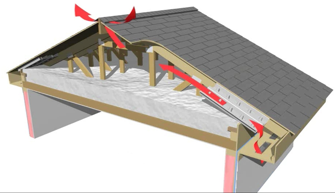
A ventilated attic is the most robust and most easily assembled roof to build when it comes to managing condensation from interior sources of moisture. It can perform well in all climate zones and provides multiple advantages in terms of durability and performance (Figure 1). From inside to outside, a ventilated attic consists of
- a finished ceiling plane (typically gypsum board)
- an air barrier and sometimes a vapor retarder (taped mudded gypsum board with all penetrations sealed can serve as the air barrier)
- insulation resting on the ceiling lid (such as blown fiberglass, blown cellulose, or batt)
- a large airspace ventilated with a combination of intake vents (placed low) and exhaust vents (placed high)
- structural roof joists or trusses
- roof sheathing/decking
- roofing underlayment or membrane
- roof cladding (such as shingles, tiles, or metal roofing).
Source
The key feature of a ventilated attic is the large airspace that separates the ceiling plane from the roof deck. This airspace provides many important benefits that are more difficult to replicate in compact roof designs:
- a large cavity that can easily accommodate thick layers (high R-value) of inexpensive insulation
- a simpler, more continuous ceiling plane for installation of the thermal barrier, air barrier, and vapor retarder
- a large volume of ventilation air that can keep the roof deck cold in the winter (helping to prevent snow melt and ice dams)
- a roof deck that is back-ventilated to help dry out any leaks or condensation that may occur
- a roof deck that is easily inspected for water leaks or signs of moisture damage.
Many of these benefits help to eliminate or control the effects of condensation. However, it is important to realize that the roof deck in a ventilated attic will be cold, often below the dewpoint. Therefore, the primary mechanisms to control condensation in a ventilated attic are 1) controlling air leakage from the house into the attic space and 2) providing proper intake and exhaust ventilation within the attic, for example, continuous ridge and soffit vents, with insulation baffles to keep the soffit vents clear for air flow.
The Vented Compact Roof
Sometimes a compact roof (i.e., a vaulted or cathedral ceiling) is chosen instead of a ventilated attic, whether for architectural reasons or to create additional interior space. In these cases, a vented compact roof (Figure 2) can provide some of the same benefits as a ventilated attic, although typically at a higher cost.
From inside to outside, a vented compact roof is comprised of
- a finished ceiling plane (typically taped, mudded gypsum board which serves as an air barrier)
- sometimes a vapor retarder, which can also serve as an air barrier
- dense-packed insulation or spray foam sandwiched between structural roof joists
- a thin, vented airspace, typically created by vent chutes stapled to the underside of the roof deck
- roof decking
- roofing underlayment or membrane
- roof cladding (such as shingles, tiles, or metal roofing).
The Unvented Compact Roof with Vented Over-Roof
Sometimes a compact roof (i.e., a vaulted or cathedral ceiling) is constructed with no ventilating air gap between the insulation and the underside of the roof deck. (The joist cavity could be completely filled with blown insulation or the underside of the roof deck could be covered with spray foam insulation.) This could be built as an unvented “hot roof” assembly with the underlayment and roof cladding attached directly to the roof sheathing. However, an unvented compact roof is not recommended, especially in cold climates in high snow load regions, because the under-deck venting with cold outside air is what keeps the roof deck cold, which helps to prevent ice dams.
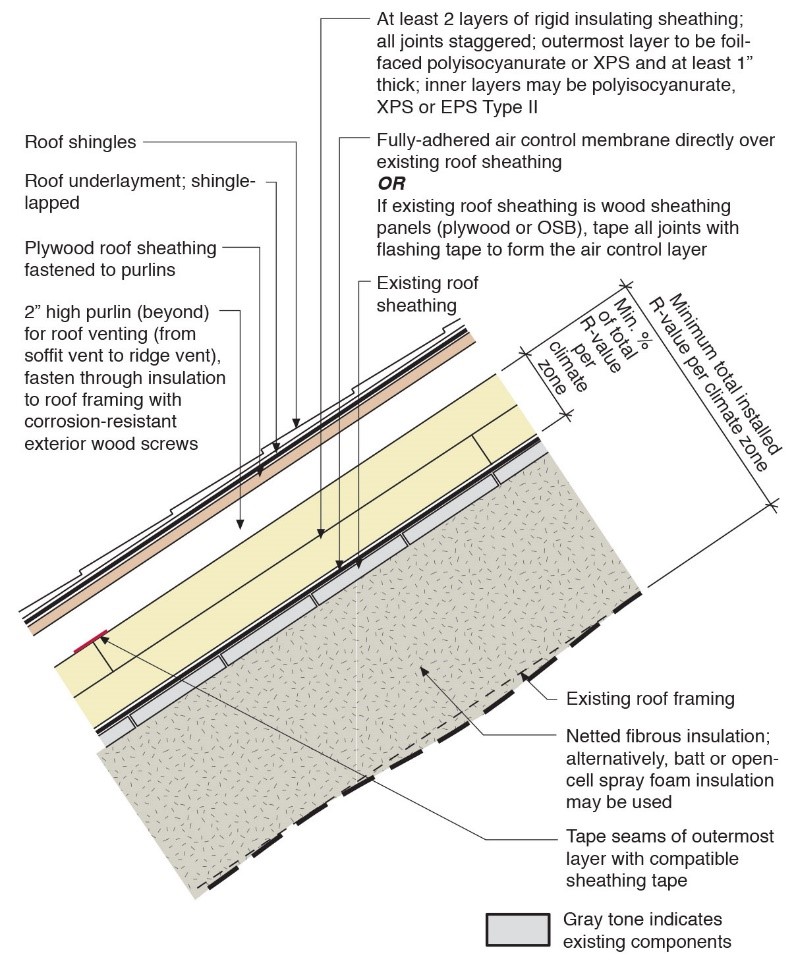
The ice dam risk can be avoided by installing a vented “over-roof” over an unvented roof. A vent space is created above the roof deck through the use of furring strips fastened on top of the roof deck and underlayment (Figure 3). In such an approach, this first roof deck installed on top of the joists should consist of a sheathing that is vapor permeable, such as fiberboard or gypsum board. The furring strips then support a second roof deck, which acts as the nail base for the roofing. One advantage of this approach is that it accommodates the use of exterior insulation, which can be installed outboard of the roof joist cavity over the first sheathing layer and under the furring strips. See the Solution Center guide Above Deck Rigid Foam Insulation for Existing Roofs for more information. This insulation warms the roof sheathing below it, helping to prevent condensation on the inside face of the roof deck and joist cavities.
Source
From inside to outside, an unvented compact roof with vented over-roof is comprised of the following layers. Figure 3 depicts these layers in a retrofit but the same layers would be used in new construction.
- a finished ceiling plane (typically taped, mudded gypsum board which serves as an air barrier)
- sometimes a vapor retarder, which can also serve as an air barrier
- dense-packed insulation or spray foam sandwiched between structural roof joists
- roof decking with seams taped
- roofing underlayment or membrane
- one or more layers of rigid foam with seams staggered and joints taped.
- furring straps
- a second sheathing layer
- underlayment or membrane
- roof cladding (such as shingles, tiles, or metal roofing).
How to Construct Attic Assemblies to Avoid Condensation during Cold Weather
The likelihood of getting damaging condensation in roof assemblies can be reduced by following the construction techniques described below.
Use back-ventilated roof sheathing.
- Design and construct a ventilated attic. Install ridge and soffit vents. Install baffles and insulation dams to keep soffit vents clear. Baffles should maintain 2 inches of clearance between roof deck and top of insulation. Design roof with raised heel trusses if needed to maintain full insulation depth plus 2-inch ventilation gap between insulation and roof deck at eaves.
- Or, design and construct a vented compact roof assembly (vaulted ceiling). Install baffles as described above.
- Or, design and construct an unvented compact roof assembly that is vented above the roof deck by installing furring strips over the first deck to provide a ventilation gap under a second roof deck/nail base for the roof cladding.
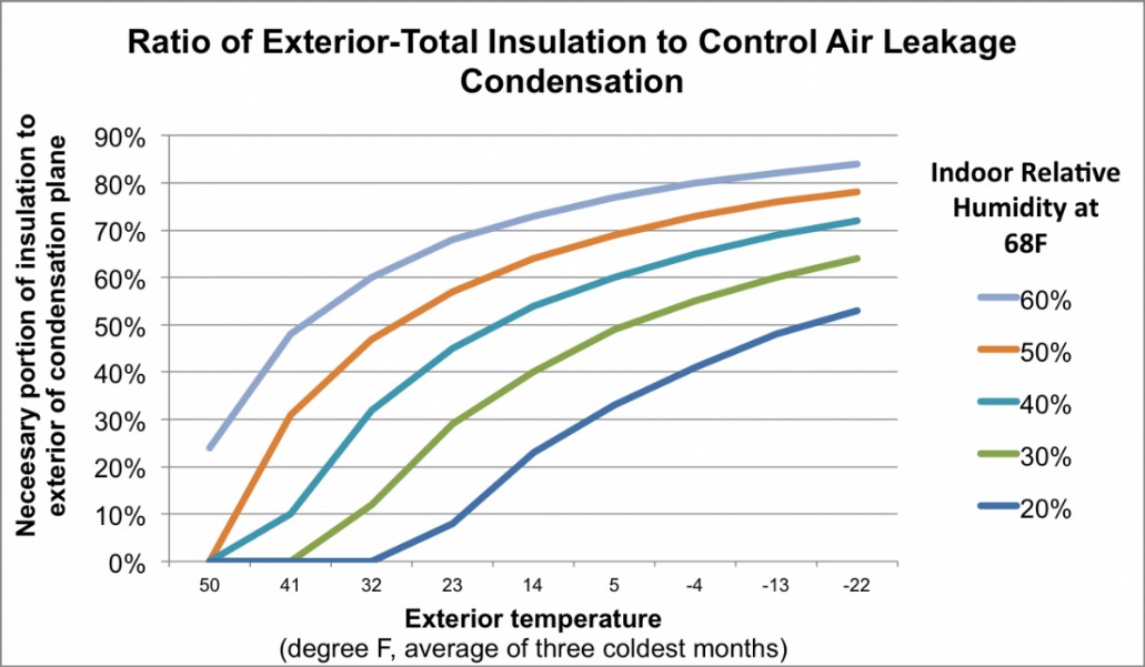
In cold climates, install insulation over the first layer of decking to keep the roof deck and roof framing warm and above dewpoint (see Figure 3 above and the Solution Center guide Above Deck Rigid Foam Insulation for Existing Roofs for installation details. Add dense-packed insulation in the roof joists if desired but more R-value must be outboard of the roof deck than in the cavity to effectively limit condensation. See Figure 4 (Straube 2011).
Source
Article describing research encouraging use of exterior insulation to warm interior sheathing surfaces in walls and roof assemblies to reduce the likelihood of condensation during cold weather
- In ventilated attics, ensure adequate attic venting area.
Residential building codes typically require 1 square foot of net free area (NFA) per 150 (up to 300) square feet of attic floor space, measured at the ceiling plane. In cold climates where condensation is likely, increased ventilation is a priority and it is helpful to meet the 1/150 ratio. See the Solution Center guide Calculating Attic Passive Ventilation for more information. Ideally, the net free area should be divided equally between passive exhaust and intake vents. The exhaust vent area should never exceed the intake area, although it may be acceptable and/or desirable to increase the intake area beyond the code minimum. Intake vents should be located low in the roof, typically in the soffits of the roof eaves, while exhaust vents should be located high, typically at the ridge. Although the residential building code does not require it, ventilation product manufacturers often suggest increased ventilation for steeper roof pitches: 1.2 x NFA for 7:12 to 10:12 pitches and 1.3 x NFA for 11:12 and higher pitches. These guidelines are helpful because steeply pitched roofs enclose a greater volume of air. Adequately ventilating that increased volume requires increased venting area. - For both compact roofs and attics, ensure the air barrier is complete and well-sealed.
This can be a challenge in many new homes due to the frequent penetrations made in the ceiling for recessed lighting, wiring, vent piping, and/or ducts. In some cases, a thin application (1 to 2 inches) of spray foam is applied over the entire ceiling lid to help seal these many holes and penetrations (see Figure 5). Loose fill insulation is then blown over the top to the desired R-value. Another option is to use furring strips to create a dropped ceiling below the first ceiling. This creates an empty cavity of a few inches that can be used for installing lighting and running wires without penetrating the air barrier above. For compact roofs with insulated and framed cavities, limit the air flow within the framing cavities by using dense-packed insulation or spray foam. Batt insulation is susceptible to poor installation and/or slumping, creating open air pathways and gaps where convection currents can form that may pull warm humid interior air throughout the cavity and increasing the likelihood of condensation.
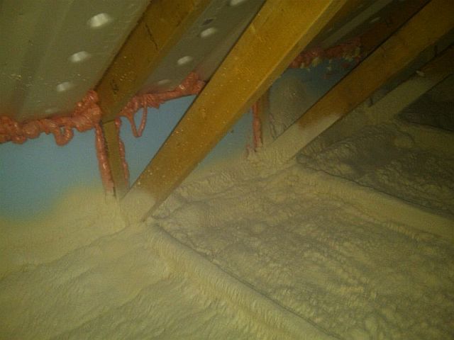
Source
There are several Solution Center guides that describe installation best practices for attic air sealing; here are some of them. See also the report Measure Guideline: Guide to Attic Air Sealing by Lstiburek 2014.
- Air Sealing Bathroom and Kitchen Exhaust Fans
- Air Sealing Attic Access Panels/Doors/Stairs
- Air Sealing Recessed Light Fixtures Below Unconditioned Space
- Attic Eave Minimum Insulation
- Ceilings
- Dropped Ceiling/Soffit Below Unconditioned Attic
- Insulating and Air Sealing Existing Non-ICAT Recessed Lights
- Roof Vents
- Roof/Attic to Exterior Wall Air Control Upgrade
- Unvented Attic Insulation
- Unvented Conditioned Attic with Spray Foam Insulation Below Roof Deck
- Unvented Insulated Sloped Roofs
- Vented vs Unvented Attic
- Manage pressure differences between indoor and outdoor air to help reduce air leakage.
Although it’s not feasible to entirely eliminate pressure differences, there are a number of important strategies that can minimize them and reduce the amount of indoor air driven into the attic or compact roof assembly. These strategies include the following:- Use balanced ventilation (such as an HRV- or ERV-based system) and minimize exhaust or supply-only fans.
- Use well-sealed ducts rather than framing cavities to move conditioned air around the building.
- Place ducts and HVAC equipment in conditioned space within the air barrier of the home. If this equipment needs to be placed in the attic, consider moving the air barrier to the roof deck and turning the attic into conditioned space.
- Install sealed-combustion appliances.
- Provide dedicated make-up air for exhaust devices such as clothes dryers and kitchen range hoods.
- Ensure adequate indoor ventilation to keep relative humidity at an acceptable level during the heating season.
As new buildings become more airtight, humidity from daily activities such as showering and cooking can build up inside the building and the importance of balanced mechanical ventilation increases. Most sources recommend an indoor relative humidity of between 30% and 50% during the heating season. (See Figure 6).
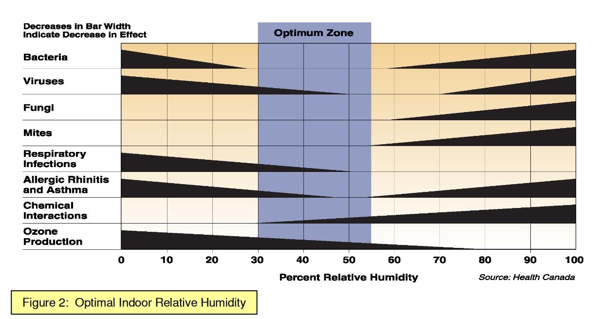
Source
3. Use building materials that provide safe moisture storage when possible.
Solid wood, treated cellulose, treated fiberboard, and plywood have safe moisture storage capacities. Many wood products made from smaller wood pieces (OSB, MDF, and the paper facing on gypsum board) offer some storage as well but are more easily damaged by moisture and provide more readily available nutrients for mold growth. Plastics, foams, and fiberglass have little to no storage capacity and tend to concentrate water on sensitive materials in the roof assembly.
Ensuring Success
Ensure the integrity of the air barrier between the home’s conditioned space and the attic. Inspect the air barrier for continuity and check its performance with a blower door test. Identify any sources of air leakage and seal those before insulating and installing finish materials.
If condensation does occur, it is imperative that moisture can dry quickly. Since roofing materials are generally vapor-impermeable, ensuring adequate venting below the roof decking is the only viable means to dry the assemblies. Maintain 2 inches of spacing for air flow within roof cavities and meet or exceed code-required vent area.
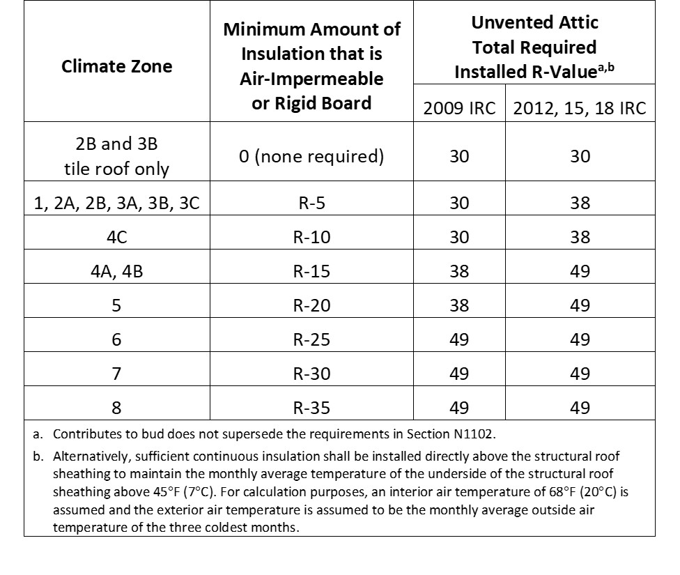
Typical R-values for common insulation materials are summarized in this table, which also identifies the vapor retarder classification for each insulation.
Region
Cold Climates
In climates with high roof snow loads (Figure 1), roof venting becomes even more critical to help prevent not only condensation, but also melting of the bottom layer of snow, which leads to ice dams and associated moisture damage. However, roof vents at the top of roof can become covered with snow. There are three options to deal with this issue:
- Manually remove snow from the peak of the roof to uncover the vents. (Not recommended due to inherent safety risks.)
- Use cupola-style vents at the ridge, which can be built tall enough to stand above the highest anticipated snow level.
- Increase the area of soffit venting. In windy conditions, soffit venting on the leeward side of the house will act as an exhaust vent if the ridge vents are blocked, although venting volume will likely still be reduced.
Note that gable-wall vents are not recommended due to their inability to adequately distribute ventilation air across the roof surface and the likelihood of admitting wind-blown snow, rain, and wildfire embers into the attic.
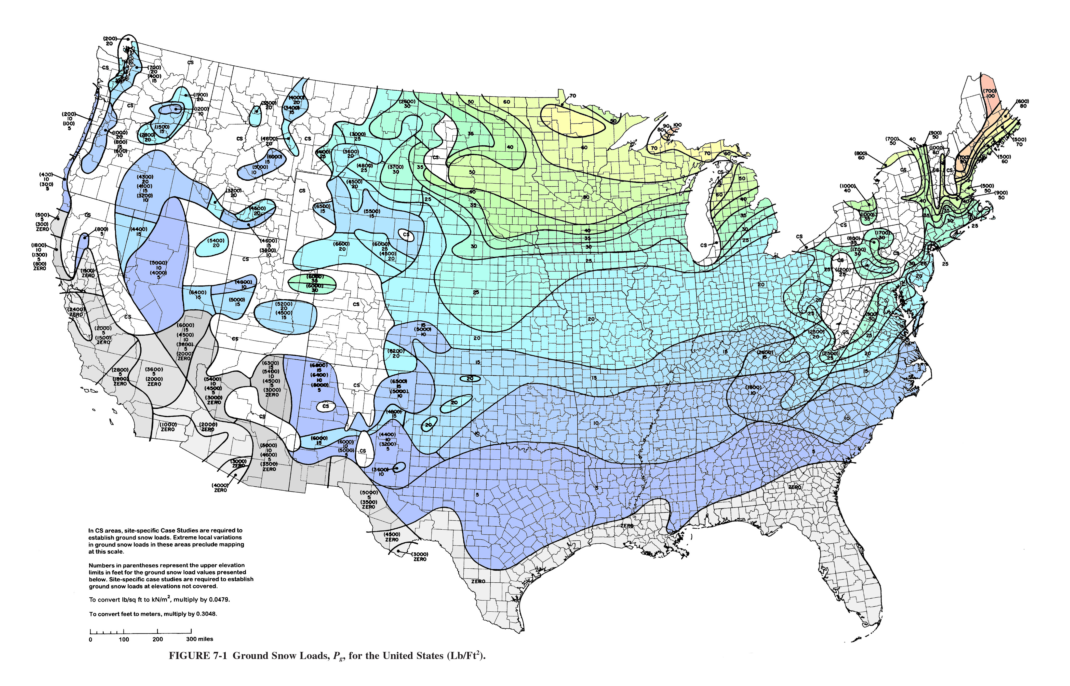
Source
Webpage providing information about design snow loads and a free interactive ground snow load mapping tool for the contiguous United States, as well as snow load calculation methods.
Training
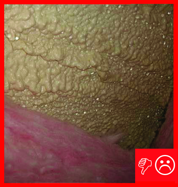
Right and Wrong Images
Source
Report covering moisture and leakage issues associated with spray foam insulation application to the underside of roof sheathing.
Source
2009 edition of code for residential buildings that creates minimum regulations for one- and two-family dwellings of three stories or less, bringing together all building, plumbing, mechanical, fuel gas, energy and electrical provisions for one- and two-family residences.
Source
Article describing research encouraging use of exterior insulation to warm interior sheathing surfaces in walls and roof assemblies to reduce the likelihood of condensation during cold weather
Source
Presentations

Videos
Compliance
Retrofit
For roof retrofits, the general approaches and construction techniques to limit condensation remain the same as those for new construction. The most important retrofit strategies that help control condensation are discussed below:
- Re-roofing projects are generally a good opportunity to upgrade roof venting. Gable-wall vents can be replaced with dedicated intake and exhaust vents that meet code requirements for placement and venting area. Under-eave soffit vents are frequently the best choice for intake vents in cold climates because they are rarely blocked by snow and ice. However, if the roof does not have soffits, a vented drip-edge or fascia vents may be good intake alternatives. Improved venting will help manage and reduce damage from condensation in existing roofs if and when it occurs.
- Air sealing at the ceiling plane for both ventilated attics and compact roof assemblies provides the best opportunity to limit condensation in extreme conditions. Air sealing work is especially valuable to prevent moisture damage in roofs because it also helps prevent ice dams, which can be a significant and catastrophic source of water leakage into attics in cold climates.
- Keep in mind that air sealing retrofits can lead to more humid indoor air. To counteract this, increased balanced ventilation (preferably with heat recovery in cold climates) should be combined with air sealing efforts to maintain adequate ventilation rates and reasonable indoor relative humidity levels.
- For compact roofs that are thin and lack the space for adequate insulation and ventilation, exterior insulation (above the roof deck) can be added to help reduce the risk of condensation and meet code-required R-values. To perform such a retrofit, existing roofing materials (underlayment and shingles, for example) should be removed and replaced with an airtight membrane that is continuous and sealed to the wall below. Exterior insulation can be placed over the top of this air barrier, followed by a 2-inch (or deeper) vent space created with sleepers. The sleepers provide attachment for a second back-ventilated roof deck, which serves as a nail base to support the finished roofing materials. To avoid condensation on the inside face of the original roof deck, meet or exceed the recommended ratio of exterior insulation to total insulation R-value, as shown in Figure 4 on the Description tab, adapted from Straube 2011.
- Consult the Building America Solution Center guide on Pre-Retrofit Assessment of Attics, Ceilings, and Roofs before beginning a roof retrofit.
More Info
Case Studies
References and Resources
*For non-dated media, such as websites, the date listed is the date accessed.
Questions? Comments? Contact our webmaster.