
Scope

After all holes through the ceiling are air-sealed and the baffles have been installed, then the insulation can be installed.

Install a continuous air barrier that is fully aligned with (touching) the insulation installed on top of the ceiling (on the attic floor) in a vented attic:

  • The air barrier could consist of drywall that is taped and sealed at seams, or another durable, solid surface like plywood or OSB, or house wrap or a smart  vapor retarder membrane that is sealed at the seams. Kraft-paper, paper products, or other materials that tear easily should not be used.
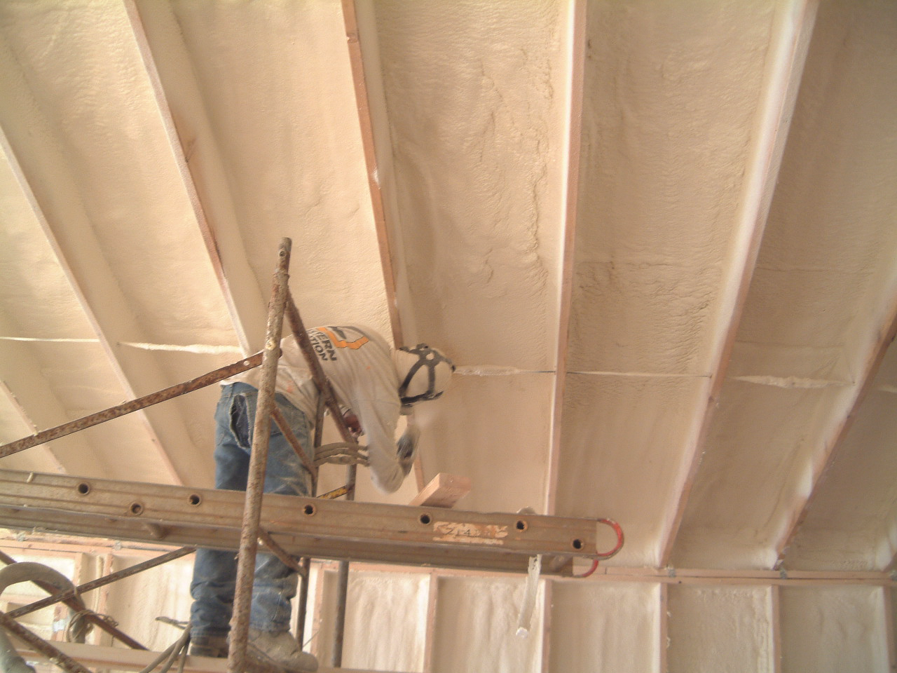
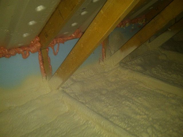
  • If spray foam insulation is used, the spray foam can serve as the air barrier if it is at least 5.5 inch thick open-cell or at least 1.5 inch thick closed-cell spray foam insulation.  
  • Install an air barrier that is continuous and in full contact with the insulation.
  • ENERGY STAR specifies that the air barrier can be installed at either the interior or exterior surface of the ceiling insulation in Climate Zones 1-3, but should be at the interior surface of the ceiling insulation in IECC Climate Zones 4-8 (ENERGY STAR). 
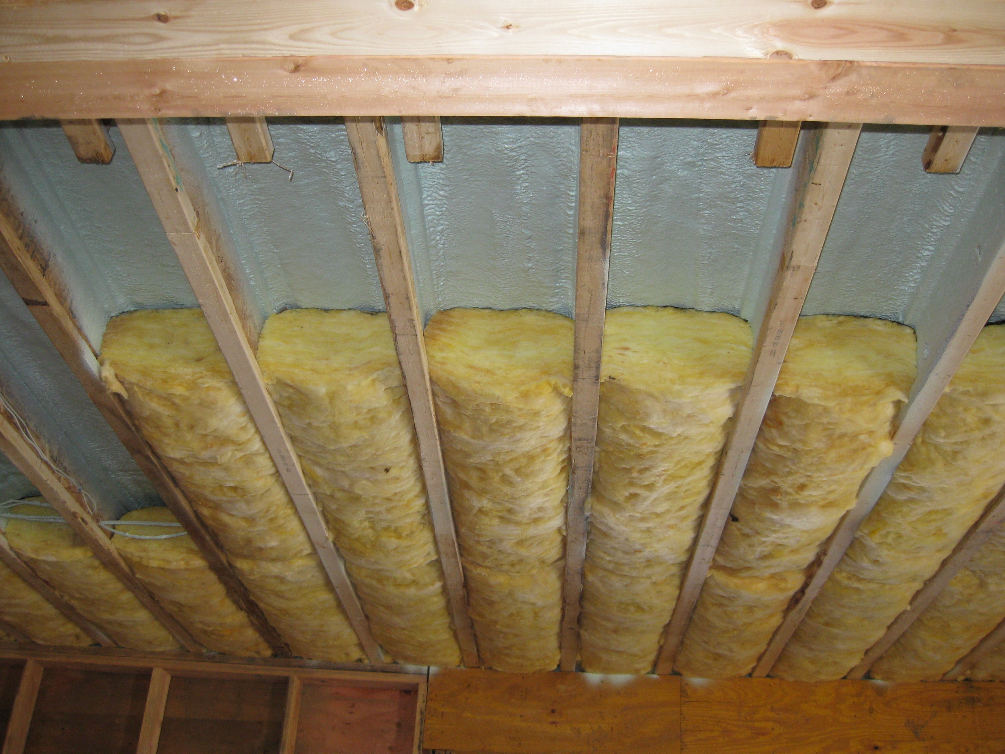
  • Install an air barrier at the vertical edges of the insulation at the attic eaves in all climate zones using a wind baffle that extends to the full height of the insulation in every rafter bay or a tabbed baffle in each bay with a soffit vent that prevents wind washing in adjacent bays. Install wind baffles with the minimum code required clearance between the baffle and the roof deck.

See the Compliance Tab for links to related codes and standards and voluntary federal energy-efficiency program requirements.

Description

In simplest terms, a house is a six-sided assembly composed of four walls, a roof, and a floor. When these components are connected, they comprise the building enclosure or the physical shell of the home. Within these assemblies are components that comprise the home’s thermal envelope (insulation) and air barrier. For the best performance, the home’s thermal layer should be fully aligned with (in full continuous contact with) the air barrier. This guide primarily describes single-family construction. For guidance on air-sealing and insulating dwelling units in multi-story multifamily buildings where floors separate dwellings, see the Building America Solution Center guide Air Sealing and Compartmentalization in Multifamily Buildings.

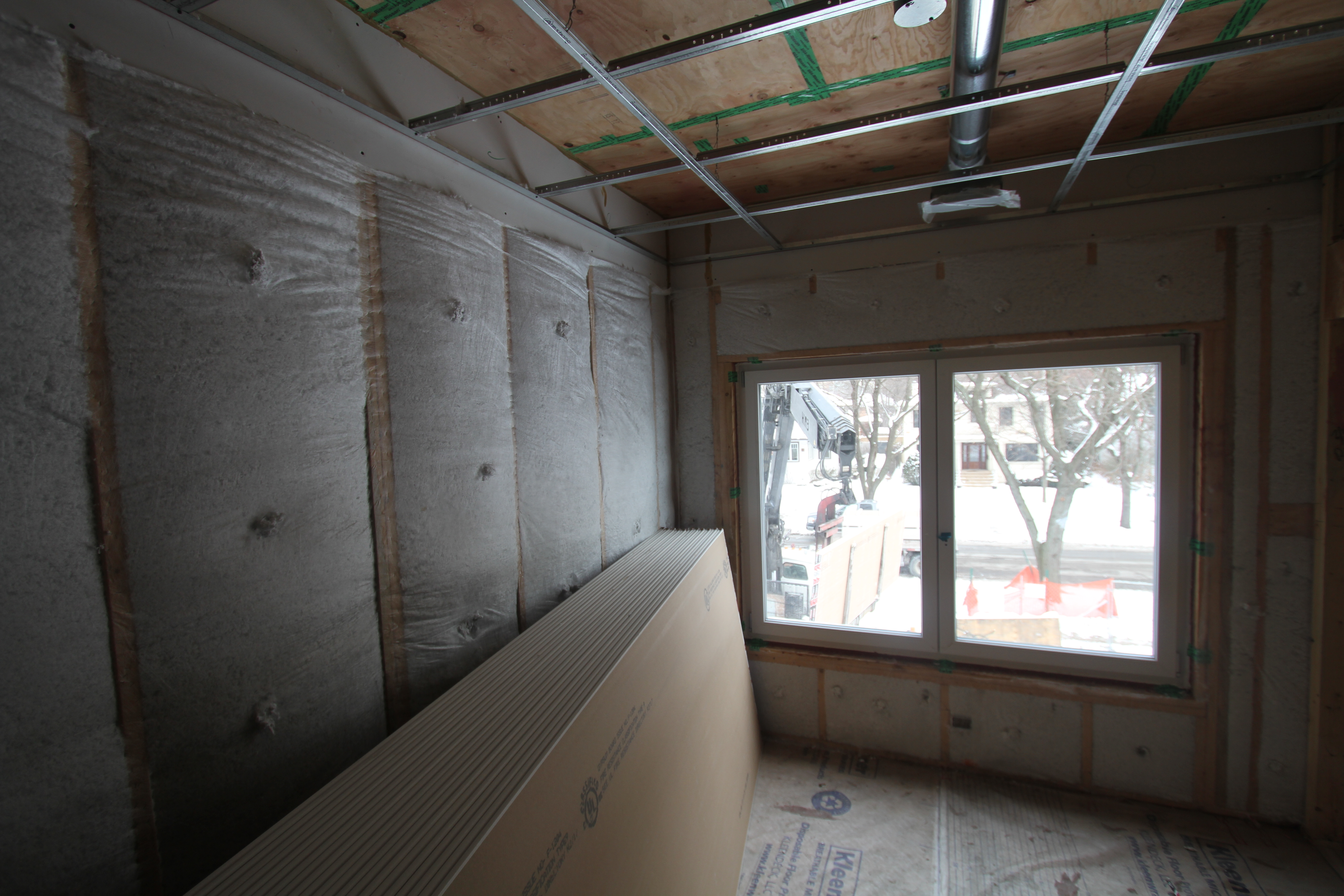
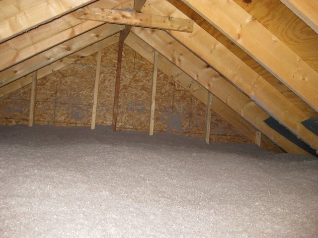
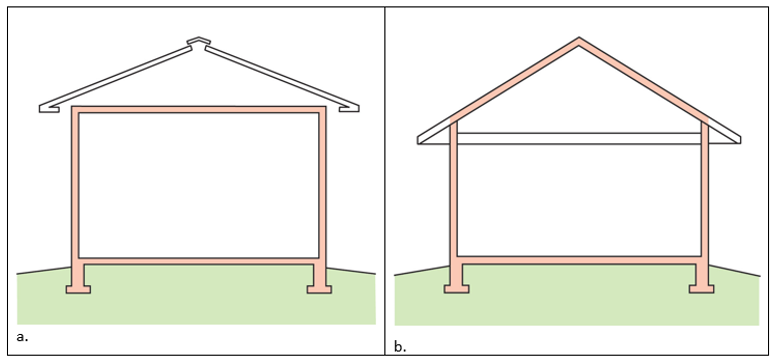
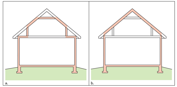
In a home with a vented attic, the ceiling provides the air barrier. The insulation in the vented attic should be in full contact with the ceiling below, which provides the air barrier for the top of the building enclosure (Figure 1).

After all holes through the ceiling are air-sealed and the baffles have been installed, then the insulation can be installed.
Source
Figure 1. After all holes through the ceiling are air- sealed and the baffles have been installed, the insulation can be installed in full contact with the ceiling drywall, which is the air barrier (Source: Courtesy of PNNL).

The ceiling air barrier usually consists of taped, mudded drywall, and should be continuous with all holes through it (such as for wiring, electrical boxes, light fixtures, flue and chimney pipes, duct chases, heating registers, soffits, etc.) thoroughly air-sealed before insulation is installed. For specific guides on air-sealing these and other items in the Building America Solution Center search for "air sealing" or by specific topics. For more on air-sealing the top plates to the ceiling drywall to provide a continuous ceiling air barrier, see the guide Air Sealing Drywall to Top Plates.

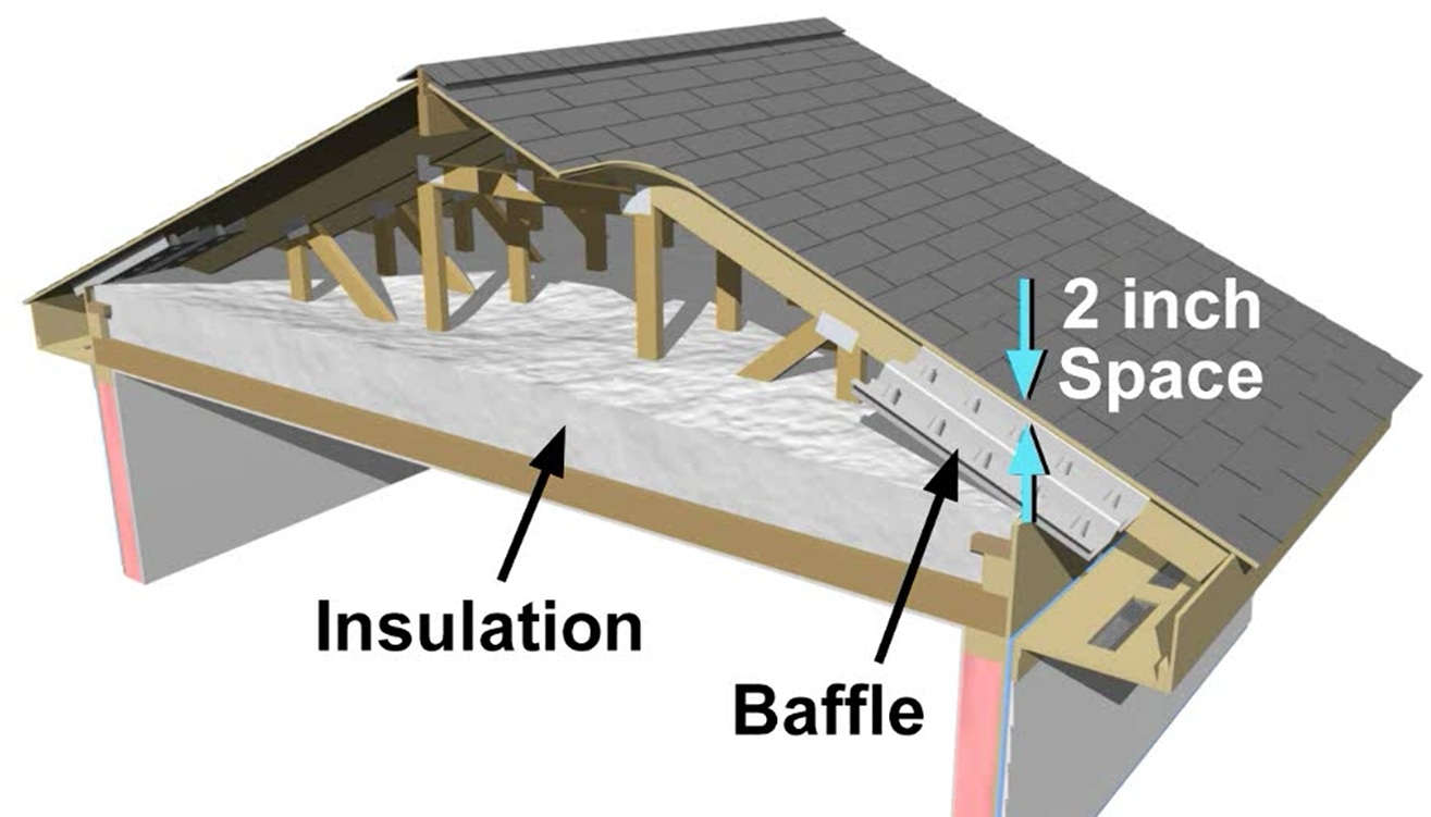
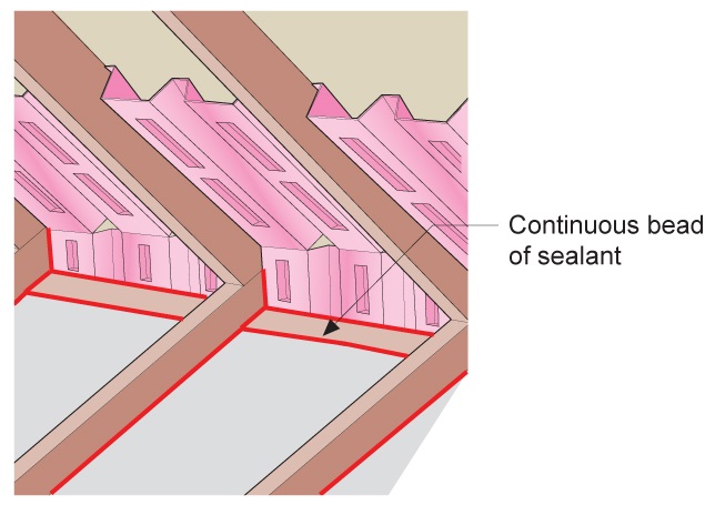
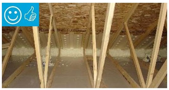
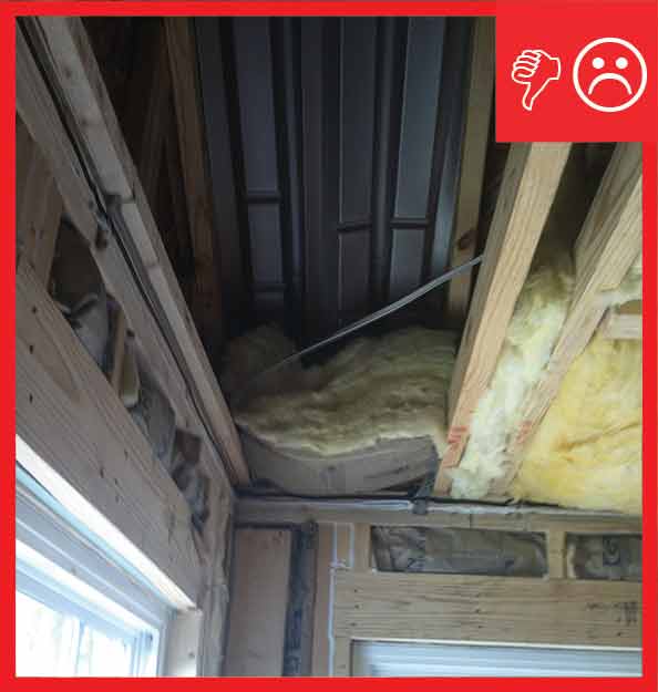
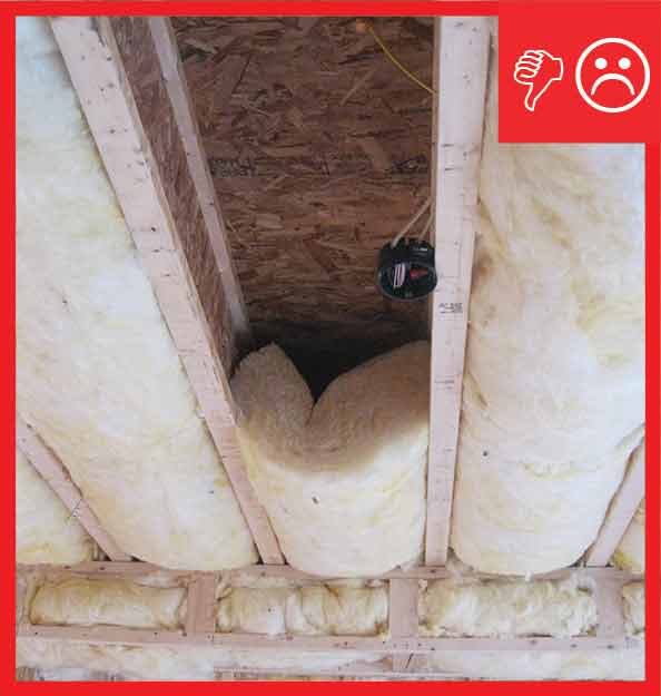
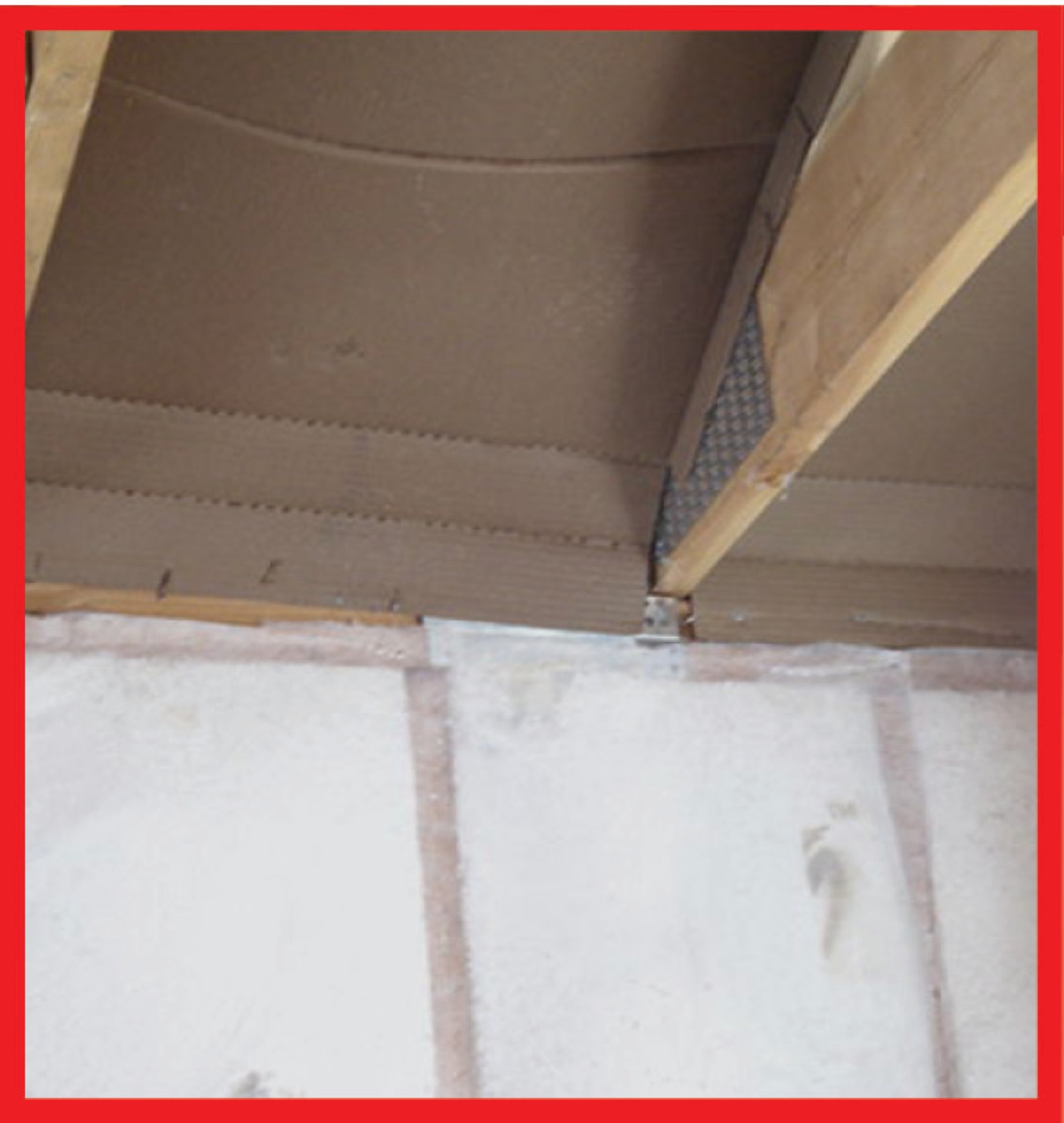
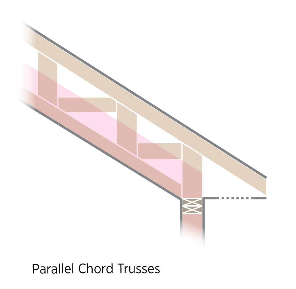
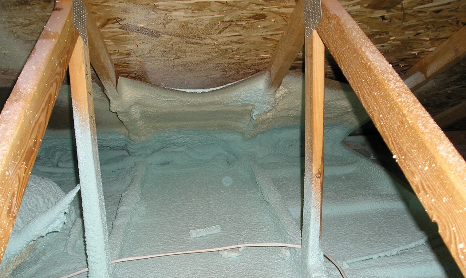
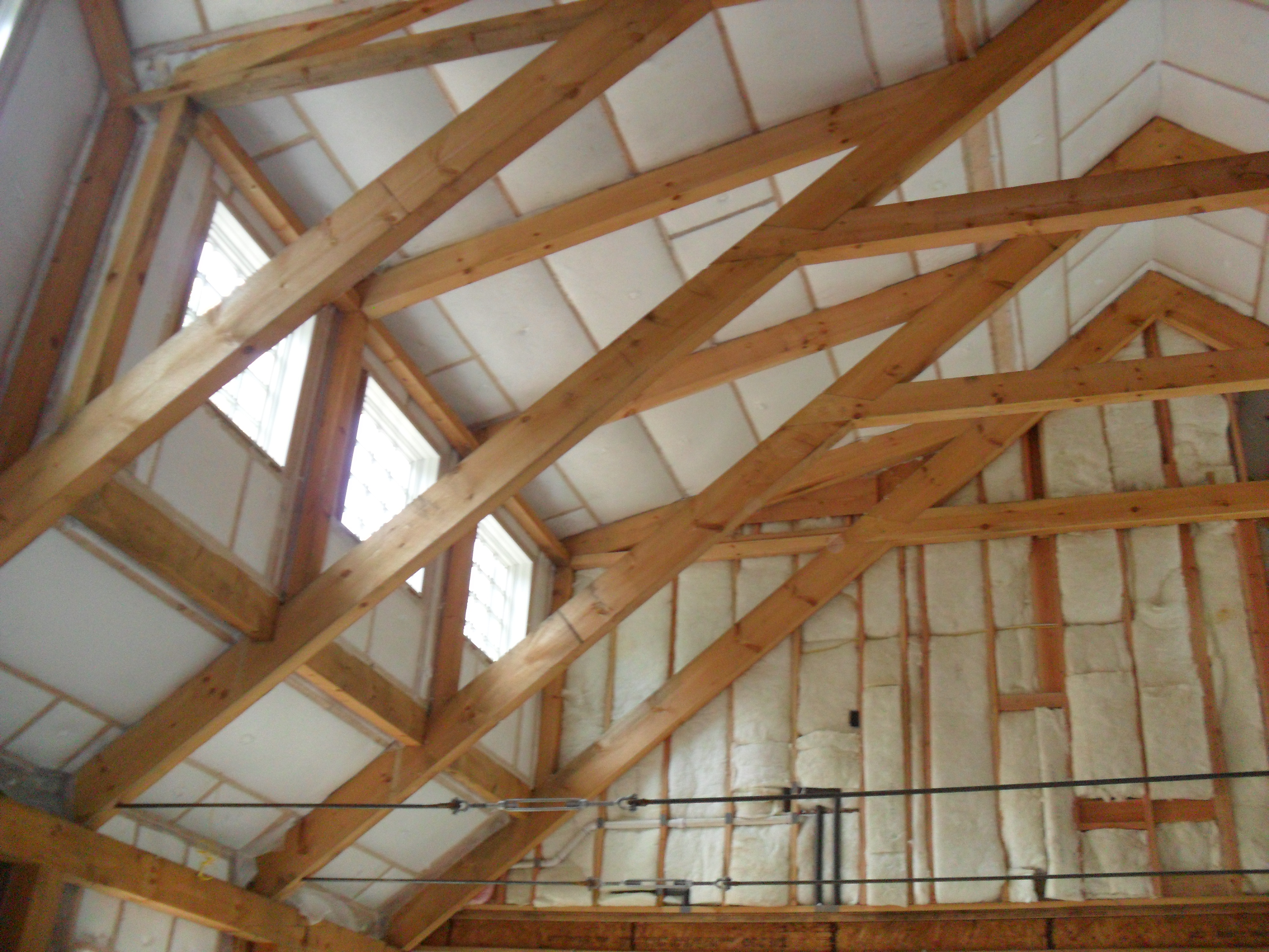
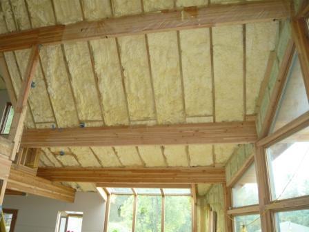
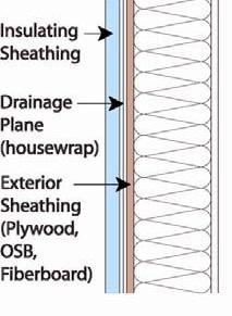
To help maintain consistent insulation over the ceiling air barrier, wind dams and baffles should be installed in the attic in every rafter bay that has a soffit vent (Figure 2). A wind dam (or a soffit dam as in Figures 3 and 4) consists of a piece of rigid material (like rigid foam, OSB, or plywood), that is installed vertically at the outside edge of the top plate. It is sealed to the top plate and extends up to the baffle. The wind dam and the baffle together direct air that flows in through the soffit vents to flow up along the underside of the roof deck to the ridge vents. It prevents wind that enters the soffit vent from pushing insulation away from the eaves and it also provides a "backstop" when insulation is installed to keep the insulation from covering the soffit vents. In some cases the exterior wall sheathing extends up to provide the wind dam (Figure 1). 

Seal the drywall to top-plate seams and the lower edge of baffles to the top plate to prevent the air coming from soffit vents from flowing under baffles into insulation.
Source
Author(s)
Lstiburek Joseph W
Organization(s)
Building Science Corporation,
BSC
Description

Document providing background and approach for the prep work necessary prior to adding attic insulation - focusing on combustion safety, ventilation for indoor air quality, and attic ventilation for durability.

Figure 2. Baffles can be made of plastic, metal, cardboard, or molded rigid foam, and guide air from the soffit vents up over the insulation and along the underside of the roof deck. These baffles have wind dams that are sealed to the outside edge of the top plate and prevent air from blowing in from the soffit vents and pushing the insulation (Source: Attic Air Sealing Guide and Details, GM-1001).
Raised heel energy trusses extend past the exterior wall and are deeper at the wall allowing room for full insulation coverage over the top plate of the exterior walls.
Source
Figure 3. Raised heel energy trusses extend past the exterior wall and are deeper at the wall allowing room for full insulation coverage over the top plate of the exterior walls (Source: Courtesy Of Georgia Department of Community Affairs).
A site-built rafter roof with a raised top plate allows for more insulation underneath.
Source
Figure 4. A site-built rafter roof with a raised top plate allows for more insulation underneath (Source: Courtesy Of Georgia Department of Community Affairs ).

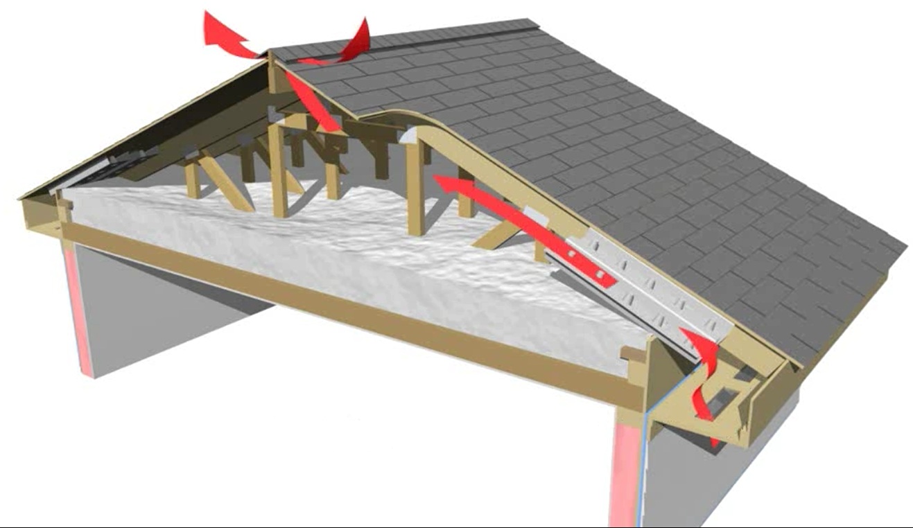
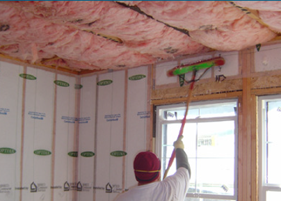
Baffles are 2-inch-deep chutes made of plastic, cardboard, or metal, 2 to 4 feet in length, and 16 or 24 inches wide to fit in 16 inch on center (o.c.) or 24 inch o.c. rafter bays (Figure 4). They can be connected to the wind dam or they often come with a flat tab at the end that can be bent down to serve as the wind dam. The baffle maintains a 2 inch air gap between the underside of the roof deck and the insulation to guide air from the soffit vents up along the underside of the roof to ridge vents (Figure 5). The baffles also help to protect the insulation from wind washing.


The soffit dam and baffle allow air to flow through the vents without disturbing the insulation covering the top plates
Source
Figure 5. The soffit dam and baffle allow air to flow through the vents without disturbing the insulation covering the top plates (Source: Courtesy of PNNL).

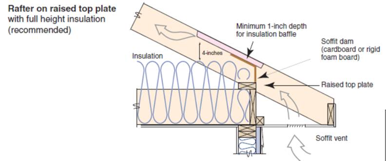
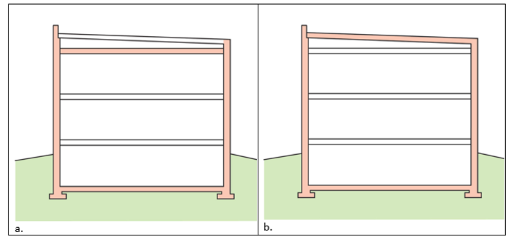
It is important to maintain a minimum amount of insulation, preferably equivalent to the insulation depth of the rest of the attic, over the top plates of the exterior walls. This will prevent cold spots along the exterior walls and ensure a consistent R-value across the ceiling. Building the roof with raised heel “energy” trusses or rafters (Figures 3 and 4) will allow the full height of insulation to be installed over the top plates. See Attic Eave Minimum Insulation for more information.


HOW TO AIR-SEAL AND INSULATE THE CEILING

  1. Design the home with raised heel energy trusses if you are using trusses (Figure 3) or roof rafters with a raised top plate if you are building the rafters on site (Figure 4).
  2. Thoroughly air-seal all holes through the ceiling.
  3. Install baffles in each rafter bay that has a vent. Choose and install the baffles correctly to provide the code-required minimum air space between the baffle and the roof deck.
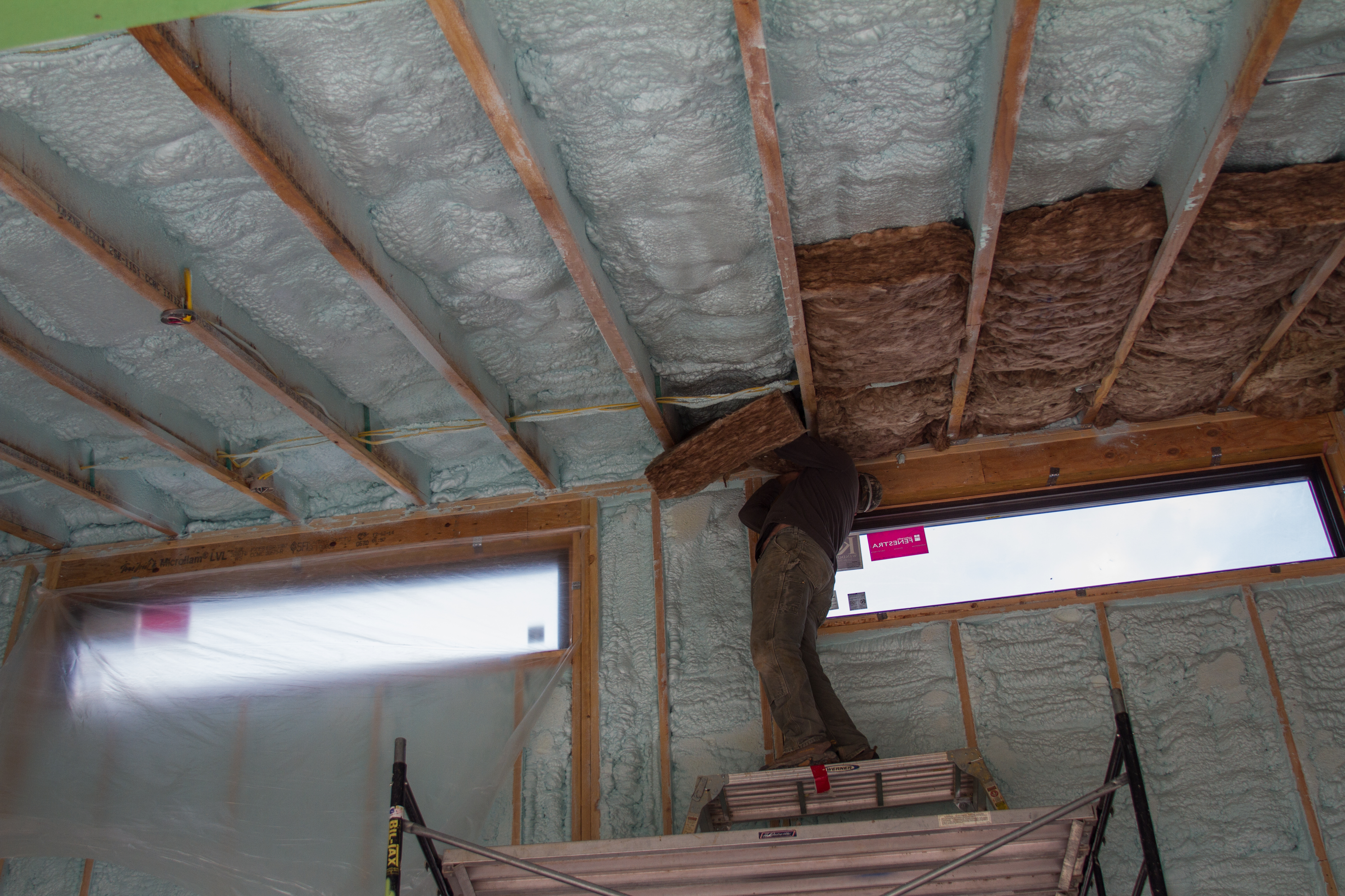
  4. Cover the ceiling deck with blown, batt, or spray foam insulation to the full height required to meet or exceed the minimum value for the climate zone. ENERGY STAR requires that all insulated ceiling surfaces meet the requirements for ceilings, regardless of slope (e.g., cathedral ceilings, tray ceilings, conditioned attic roof decks, flat ceilings, sloped ceilings).

Ensuring Success

Verify with a visual inspection that a continuous air barrier exists at the interior surface of the ceilings in Climate Zones 4-8 and at the interior or exterior surface of ceilings in Climate Zones 1-3. This air barrier should be fully aligned with the insulation across the entire surface of the ceiling including at the eaves. Verify that wind dams and baffles are installed in every bay with a soffit vent to prevent wind washing. Measure baffles to confirm that the baffles meet the minimum code-required clearance between the baffle and the roof deck. 

Region

Minimum insulation levels for attics are specified by climate zone in the International Energy Conservation Code (IECC). The insulation levels for the past several IECC and IRC code versions (2009, 12, 15, 18, and 21) are summarized in the Solution Center in the 2009-2021 IECC and IRC Minimum Insulation Requirements for New Homes.
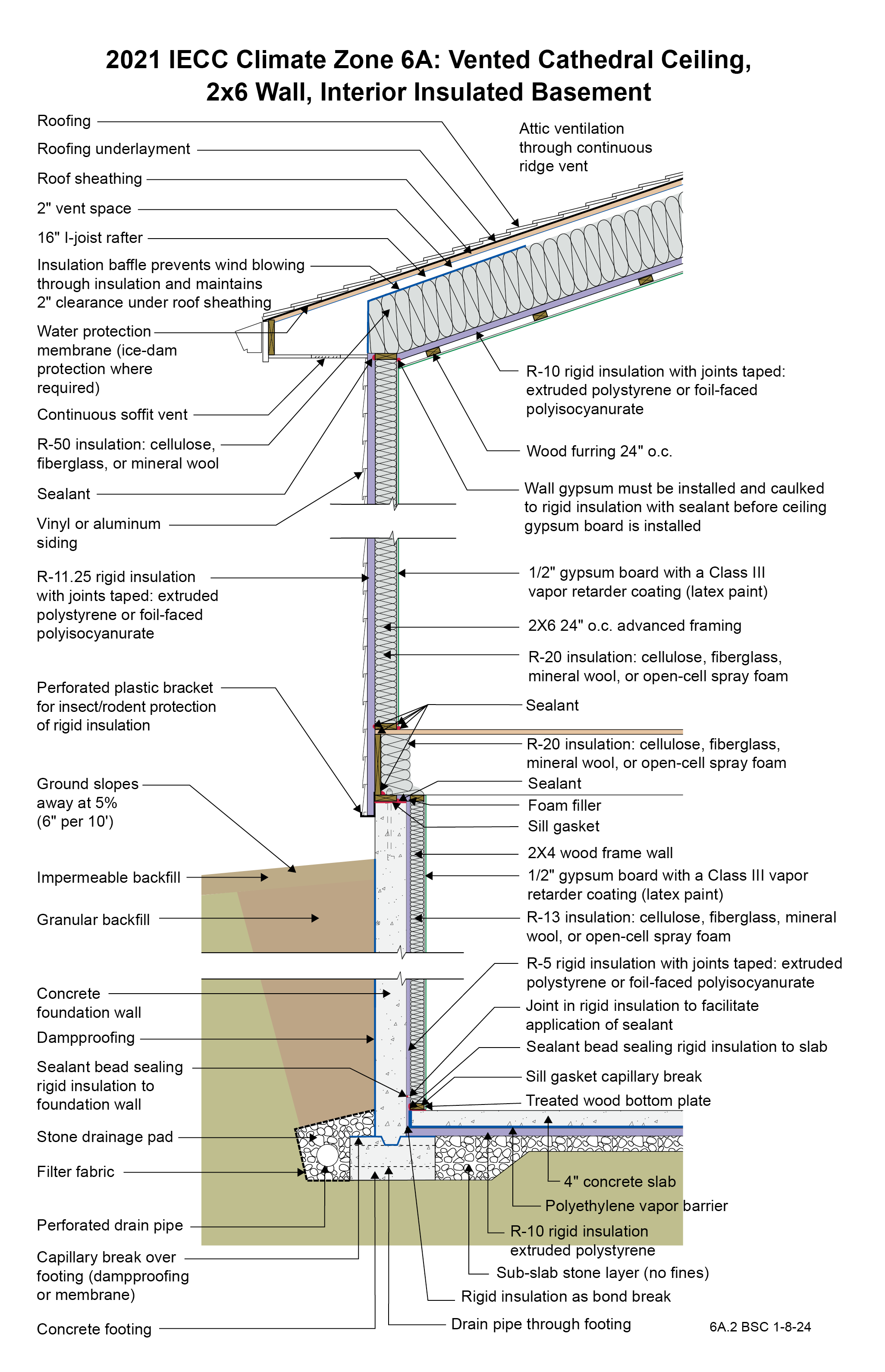
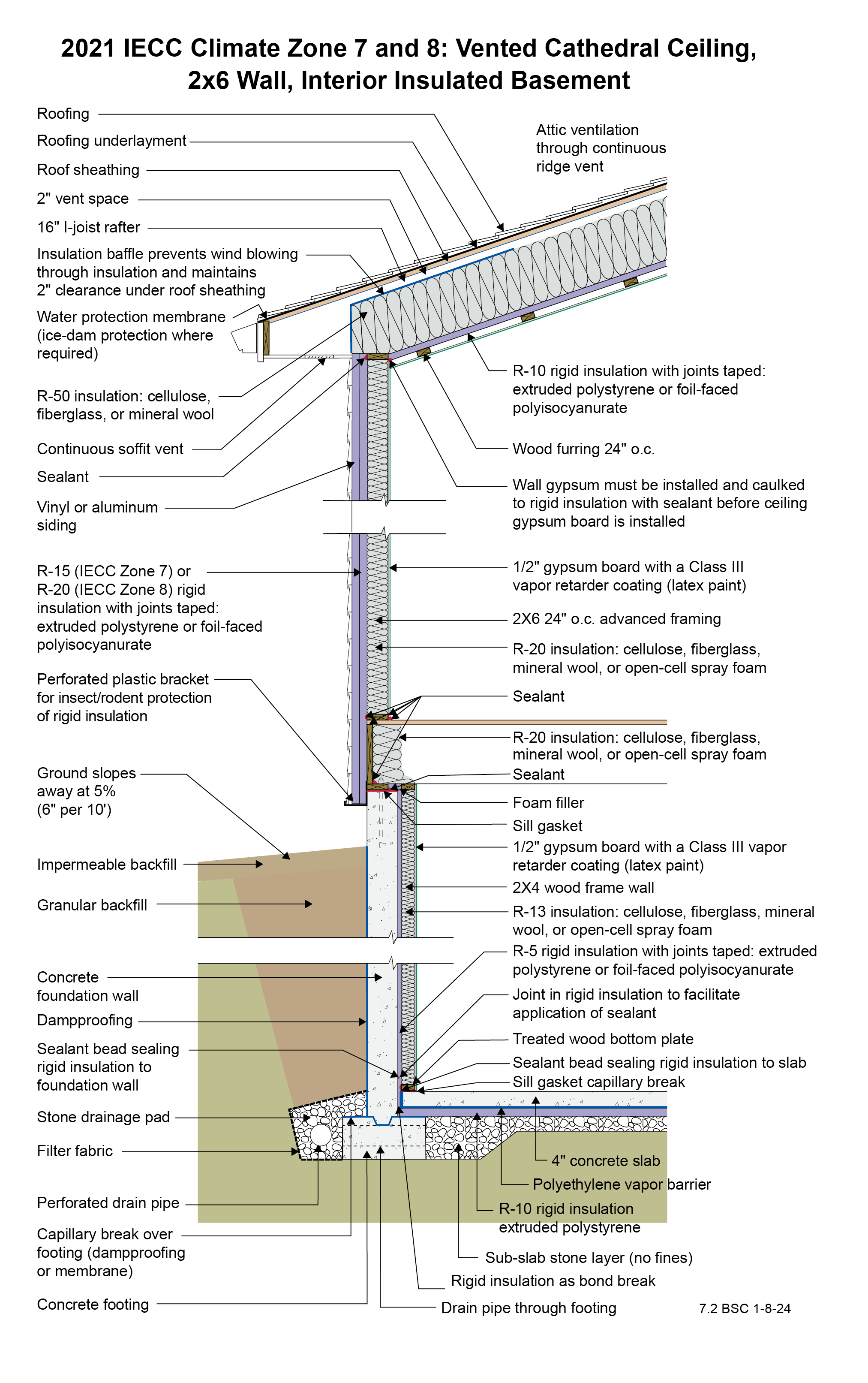
To determine your climate zone see the maps below or go to the 2021 IECC Climate-Specific Building Assemblies tool in the Solution Center and click on the “Help me find by Climate Zone”: button. The map in Figure 1 shows the climate zones for states that have adopted energy codes equivalent to the 2009, 12, 15, and 18 IECC. The map in Figure 2 shows the climate zones for states that have adopted energy codes equivalent to the IECC 2021. 


IECC climate zone map
Source
Author(s)
International Code Council
Organization(s)
ICC
Description

2012 edition of code establishing a baseline for energy efficiency by setting performance standards for the building envelope (defined as the boundary that separates heated/cooled air from unconditioned, outside air), mechanical systems, lighting systems and service water heating systems in homes and commercial businesses.

Figure 1. Climate Zone Map from IECC 2009, 12, 15, and 18. (Source: 2012 IECC)
Climate Zone Map from IECC 2021
Source
Author(s)
International Code Council
Organization(s)
ICC
Description

2021 edition of code establishing a baseline for energy efficiency by setting performance standards for the building envelope (defined as the boundary that separates heated/cooled air from unconditioned, outside air), mechanical systems, lighting systems and service water heating systems in homes and commercial businesses.

Figure 2. Climate Zone Map from IECC 2021. (Source: 2021 IECC)

Training

Right and Wrong Images

Right - a dropped ceiling below a taped plywood air barrier provides a service cavity for ducts and wiring.
Source
Right - A technician applies a thin layer of closed-cell foam to air-seal an unvented attic assembly before filling the ceiling joists with batt or blown insulation.
Source
Author(s)
Coble Brian
Organization(s)
Home Energy Magazine
Description

Article describing how insulating and air sealing unfinished attic spaces can lead to reduced energy bills in some homes.

Right - Closed-cell spray foam covers the ceiling and joists to insulate and air-seal the ceiling deck.
Source
Courtesy Of
BSC
Right - Spray foam insulation air-seals the ceiling-to-drywall seams at the wall top plate.
Source
Courtesy Of
BSC
Right - The wall top plates are sealed with foam before installing insulation on the ceiling deck
Right - The wall top plates are sealed with foam before installing insulation on the ceiling deck.
Source
Courtesy Of
BSC
Wrong - Batt insulation does not provide complete coverage across the attic floor so ceiling joists are exposed resulting in thermal bridging.
Source
Courtesy Of
BSC
Wrong - Batt insulation is poorly installed leaving gaps along the ceiling.
Source
Wrong - Ceiling insulation is not completely installed and air barrier is missing.
Source
Wrong - Insulation does not fill entire cavity leading to heat losses.
Source
Wrong - IR image shows a lack of air-sealing and insulation around a ceiling light fixture.
Source
Wrong - Wind baffle installation will not allow insulation over the top plate.
Source
Author(s)
U.S. Environmental Protection Agency,
ENERGY STAR
Organization(s)
EPA
Description

Guide describing details that serve as a visual reference for each of the line items in the Thermal Enclosure System Rater Checklist.

2021 IECC Climate Zone 6A: Vented Cathedral Ceiling, 2x6 Wall, Interior Insulated Basement
Source
Courtesy Of
BSC
2021 IECC Climate Zone 7 and 8: Vented Cathedral Ceiling, 2x6 Wall, Interior Insulated Basement
2021 IECC Climate Zones 7 and 8: Vented Cathedral Ceiling, 2x6 Wall, Interior Insulated Basement
Source
Courtesy Of
BSC
A simple vented attic with good air-sealing of the drywall ceiling air barrier, air flow from soffit vents to ridge vents protected by ventilation baffles, and lots of insulation covering the attic floor is unlikely to encourage ice dams.
Source
Courtesy Of
BSC
Blown cellulose insulation completely fills the netted wall and ceiling cavities.
Source
Author(s)
Baechler Michael C,
et al.
Organization(s)
Pacific Northwest National Laboratory,
PNNL,
Oak Ridge National Laboratory,
ORNL,
U.S. Department of Energy,
DOE
Description

Guide describing measures that builders in the cold and very cold climates can take to build homes that have whole-house energy savings of 40% over the Building America benchmark with no added overall costs for consumers.

Closed-cell spray foam insulation covers the attic floor to provide a continuous air control layer.
Source
Courtesy Of
BSC
Drop-in ceiling assemblies consisting of suspended ceiling tiles (common in multifamily buildings) are often insulated with fiberglass or mineral wool batt insulation.
Source
Courtesy Of
BSC
Garage ceiling with spray foam, flash air-seal, and batt insulation.
Source
Author(s)
Baechler Michael C,
et al.
Organization(s)
Pacific Northwest National Laboratory,
PNNL,
Oak Ridge National Laboratory,
ORNL,
U.S. Department of Energy,
DOE
Description

Guide describing measures that builders in the cold and very cold climates can take to build homes that have whole-house energy savings of 40% over the Building America benchmark with no added overall costs for consumers.

In cathedral ceilings, parallel chord trusses allow thicker insulation levels over the exterior wall top plates.
Source
Insulation was added to the walls and ceiling of this existing home from the inside as part of an extensive retrofit to avoid replacing original 1-inch shiplapped sheathing.
Source
Limited attic access may make it necessary to use a bore scope when inspecting for missing air barriers and insulation in existing buildings.
Source
Rigid foam insulating sheathing installed over an existing garage ceiling with retrofits to air seal exterior wall before adding exterior wall insulating sheathing
Source
Author(s)
Neuhauser Ken,
Gates Cathy,
Pettit Betsy
Organization(s)
Building Science Corporation,
BSC
Description

Guidebook providing useful examples of high performance retrofit techniques for the building enclosure of wood frame residential construction in a cold and somewhat wet climate.

Spray foam insulates and air-seals the ceiling deck and top plates of this vented attic.
Source
The batt insulation shown here was properly installed to fill the ceiling cavities.
Source
Author(s)
Baechler Michael C,
et al.
Organization(s)
Pacific Northwest National Laboratory,
PNNL,
Oak Ridge National Laboratory,
ORNL,
U.S. Department of Energy,
DOE
Description

A guidebook helping builders in hot-humid climates design and construct homes for energy efficiency, durability, health, safety, and comfort.

The seams in the ceiling drywall are sealed from the attic side with spray foam.
Source
The unvented attic is insulated along the underside of the roof deck with 7 inches (R-49) of closed-cell spray foam, providing vaulted ceilings and a conditioned knee wall space for ducting.
Source
This vaulted ceiling has 7 inches of closed-cell spray foam plus an R-22 unfaced mineral wool batt for a total attic insulation value of R-68.
Source
The walls and ceilings of this post-and-beam home are filled with netted blown fiberglass.
Source
Three inches of closed-cell spray foam (R-19) and 7.5 inches (R-28) of open-cell spray foam was installed below the roof sheathing in this cathedral ceiling.
Source
The thermal boundary for a gable roof can be located at either a) the flat ceiling with a vented attic or b) the roof line for an unvented attic
Source
Courtesy Of
BSC
A low-sloped shed roof with the thermal boundary located at either a) the flat ceiling with a vented attic or b) the roof line for an unvented attic
Source
Courtesy Of
BSC
A 1- and ½-story home with a room located in the attic and the thermal boundary located at either a) the walls and ceiling of the attic room with small vented attic spaces or b) the roof line for an unvented attic
Source
Courtesy Of
BSC

Presentations

Publication Date
·
Author(s)
Southface Energy Institute
·
Organization(s)
SEI
Description
Presentation describing the Georgia State Minimum Standard Energy Code air barrier requirements, envelope concepts including air flow and thermal properties, and common missed insulation and air-sealing opportunities.

Videos

Publication Date
·
Author(s)
Cold Climate Housing Research Center
·
Organization(s)
CCHRC
Description
Video from Cold Climate Housing Research Center on how warm air typically leaks out of homes through attics via the stack effect and how to mitigate these effects through building practices.

CAD Files

Conceptual insulation practice at attic-style truss system - above unconditioned space
Download: DWG PDF
Conceptual insulation practice at attic-style truss system - above conditioned space
Download: DWG PDF

Retrofit

SCOPE

Retrofit an existing ceiling to establish a complete thermal barrier by air-sealing and insulating.

  • Air-seal the top plates and all penetrations through the ceiling, including the attic hatch and pull-down stair openings, chimneys, bathroom fans, recessed ceiling lights, electrical boxes, and plumbing stacks.
  • Inspect attic eaves and soffit vents. Set aside existing insulation. Re-install any missing vent grating. Replace missing baffles and wind dams. Caulk top plate-to-drywall junctures, if accessible. Install insulation to full available height over top plates.
  • See the Scope and Description tabs for additional guidance.

For more information on conditions that may be encountered when working in attics in existing homes, see the assessment guides on attics and hazardous materials.  

See the U.S. Department of Energy’s Standard Work Specifications (SWS) for more on air sealing and working in attics. Follow safe work practices as described.

DESCRIPTION

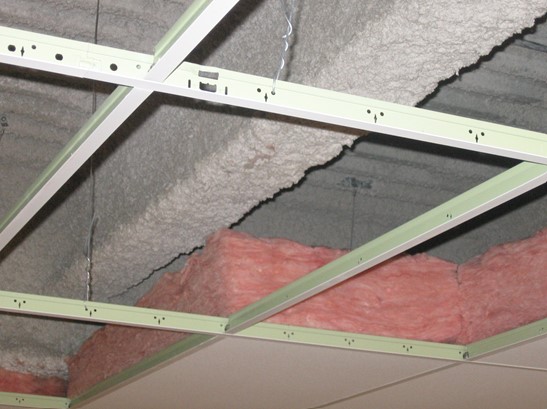
Adding attic insulation is a popular retrofit in older homes. However, before adding insulation it’s important to make sure that the ceiling deck (attic floor) is well air-sealed. The porous blown or batt insulation typically used will do little to stop the movement of conditioned air out of the home and into the attic if there are gaps such as around light fixtures, flues, or dry wall-to-top plate junctures. In a home with a vented attic, the properly air-sealed ceiling with attic insulation on top serves as an important part of the home’s thermal envelope. See the Description tab for more on this concept.  For the best performance, the home’s thermal layer should be fully aligned with (in full continuous contact with) the air barrier and the air barrier should be continuous with no air leaks.

Specific attic air-sealing measures are described in several Building America Solution Center guides, as well as in the Measure Guideline: Guide to Attic Air Sealing by Building Science Corporation. Note that locating penetrations underneath attic insulation is often challenging, and may require such steps as tracing wiring and measuring from base points visible from both the interior of the house and the interior of the attic.  Note also that not all penetrations may be accessible for sealing (for example, those located at the perimeter of the attic where there is minimal head clearance). Sealing large and accessible holes will improve energy efficiency and comfort, even if the work cannot be performed perfectly at every single penetration.

Insulation should completely cover the attic floor and the insulation depth across the attic ceiling should be consistent. See the Description tab for a description of baffles and wind dams, which help to keep insulation from getting blown away from soffit vents while maintaining a ventilation gap from soffit vents to ridge vents.

Note that, although the purpose of air-sealing is to improve energy efficiency and comfort, it is important not to compromise health, safety, and durability in the process. Combustion safety, ventilation for indoor air quality, durability, and attic ventilation should be addressed first, before performing attic air-sealing. This work will be performed inside the attic so use safe work practices and be aware of hazardous conditions as described in the attic assessment guide.

How to Insulate and Air-Seal an Existing Attic to Establish a Consistent Thermal Boundary

  1. Inspect the house, checking for combustion appliances, controlled ventilation, and required attic ventilation.
    Do not proceed if:
    • The house attic has active knob and tube wiring.
    • The house attic has vermiculite insulation.
    • The house attic has bathroom fans vented into the attic.
    • The house has a leaking roof.
    • The house has an unvented kerosene heater or gas fireplace.
  2. Ensure combustion safety. If there is a natural draft (Category 1) gas- or oil-fired furnace, water heater, or boiler located in the home, see the Pre-Retrofit Assessment of Combustion Appliances guide for more information including testing requirements. Consider replacing the natural draft appliances with a sealed combustion, induced draft, or power-vented appliance. Install carbon monoxide detectors.
  3. Ensure ventilation for indoor air quality. Air-sealing will reduce the amount of air that will enter the home through uncontrolled means. Controlled ventilation is required. See the guide Whole-Building Delivered Ventilation.
  4. Ensure Attic Ventilation. All roofs must be vented according to the applicable building code. Most residential roofs are vented with soffit vents, but ridge vents, mushroom cap vents, and gable vents are also common. The size and location of the vents should be determined by referencing the applicable building code. (See Lstiburek 2014.)
  5. Identify areas to be air sealed. This includes all penetrations through the ceiling, including the chimneys, flues, bathroom fans, electrical boxes, and plumbing stacks,  recessed ceiling lights, attic hatch and pull-down stair openings, as well as top plates for all exterior and interior walls. The contractor may want to start with a walk-through of the home, noting potential sources of leaks on a sketch of the home.
  6. Move existing insulation away from penetrations and brush away dust and debris.
  7. Air-seal gaps, seams, and holes using caulk and spray foam sealants. Rigid board material such as plywood, OSB, drywall, or rigid foam board can be secured into place to seal larger gaps. See specific guides for more on sealing electrical, plumbing, and flues and penetrations with complicated interfaces such as recessed ceiling lightsdropped soffitsattic hatch and pull-down stair openings, and top plates for all exterior and interior walls.
  8. Replace insulation and add insulation to compensate for insulation compressed during air sealing activities.
  9. Inspect attic eaves and soffit vents. Set aside existing insulation. Re-install any missing vent grating. Replace missing baffles and wind dams. Caulk top plate-to-drywall junctures, if accessible.
  10. Replace insulation and add insulation to full available height over top plates.
  11. Add insulation to desired depth across the entire attic.

More Info

Case Studies

Publication Date
·
Author(s)
Pacific Northwest National Laboratory,
U.S. Department of Energy
·
Organization(s)
PNNL,
DOE
Description
Case study describing a 4,763 ft2 certified Passive House that achieved HERS 27 without PV through the construction of R-54 walls that use ICF plus fiberglass cavity insulation, an R-100 vented attic, extensive air sealing and flashing, triple-pane windows, ductless heat pumps, and solar hot water.

References and Resources

Publication Date
·
Author(s)
ENERGY STAR
·
Organization(s)
U.S. Environmental Protection Agency,
EPA,
ENERGY STAR
Description
Guide for homeowners describing how to find and seal basement and attic air leaks, determine if attic insulation is adequate, make improvements safely, and reduce energy bills.
Publication Date
·
Author(s)
National Renewable Energy Laboratory,
U.S. Department of Energy
·
Organization(s)
NREL,
DOE
Description
Fact sheet describing an innovative aerosol-based sealing technique for tightening building envelopes in new homes, involving pressurizing the structure and dispersing an aerosol sealant "fog" to autonomously identify and seal leaks, with real-time feedback through a standard blower door and laptop...
Publication Date
·
Author(s)
Lstiburek Joseph W
·
Organization(s)
Building Science Corporation,
BSC
Description
Document providing background and approach for the prep work necessary prior to adding attic insulation - focusing on combustion safety, ventilation for indoor air quality, and attic ventilation for durability.
Publication Date
·
Author(s)
Southface Energy Institute,
Oak Ridge National Laboratory
·
Organization(s)
ORNL,
SEI
Description
Information sheet with information about insulating and ventilating attics.
Publication Date
·
Author(s)
Holladay Martin
·
Organization(s)
Green Building Advisor
Description
Information sheet presenting the correct methods for building an insulated cathedral ceiling.
Publication Date
·
Author(s)
Holladay Martin
·
Organization(s)
Green Building Advisor,
GBA
Description
Information sheet presenting techniques for installing cellulose insulation.
Publication Date
·
Author(s)
Lstiburek Joseph W
·
Organization(s)
Building Science Corporation
Description
Guideline describing information and specifications relevant to air-seal existing attics.
Publication Date
·
Author(s)
U.S. Environmental Protection Agency,
ENERGY STAR
·
Organization(s)
EPA
Description
Guide describing details that serve as a visual reference for each of the line items in the Thermal Enclosure System Rater Checklist.
Publication Date
·
Author(s)
Tobiasson Wayne N,
Tantillo Thomas,
Buska James S
·
Organization(s)
Cold Regions Research and Engineering Laboratory,
CRREL
Description
Report describing the formation of icicles and ice dams along poorly ventilated roofs and how to mitigate ventilation issues with insulation and vents.

*For non-dated media, such as websites, the date listed is the date accessed.

Contributors to this Guide

The following authors and organizations contributed to the content in this Guide.

Sales

Building Science-to-Sales Translator

Fully Aligned Air Barriers = Whole-House Draft Barrier

Image(s)

Technical Description

A whole-house draft barrier is a continuous layer of air-tight materials that block air leaks. This barrier can be integrated with other materials to also function as a water barrier, thermal barrier, and vapor barrier. For example, rigid foam insulation can be used to block thermal flow as well as air flow when seams are sealed with tape, caulk, adhesives, or liquid-applied sealants. Some rigid foams have an integrated water control layer as well. Additionally, drywall can serve as an interior air barrier when the seams are taped and spackled, and caulk, spray foam, or gaskets are used to seal around wiring, plumbing, and other penetrations. It also serves as the vapor barrier when finished with paint. Insulation should be in full contact with the air barrier layer.

Whole-House Draft Barrier
Sales Message

Whole-house draft barriers block air flow that can undermine the thermal protection with a complete high-performance insulation system. What this means to you is less wasted energy along with enhanced comfort, quiet, and durability. Wouldn’t you agree it would be a shame to only get a partial return on your investment in advanced insulation?

Last Updated

Questions? Comments? Contact our webmaster.

Disclaimer

This content is a work created with funding provided by the United States Department of Energy under Contract no DE-AC05-076RL01830 for the operation of Pacific Northwest National Laboratory. The information and guidance provided by Pacific Northwest National Laboratory (PNNL) in the content are intended solely for educational purposes only and do not constitute formal training or certification. It is provided with the explicit understanding that neither the United States Government nor the United States Department of Energy, nor the Contractor, nor any or their employees, nor any jurisdiction or organization that has cooperated in the development of these materials, makes any warranty, express or implied, or assumes any legal liability or responsibility for the accuracy, completeness, or usefulness or any information, apparatus, product, software, or process disclosed, or represents that its use would not infringe privately owned rights. Reference herein to any specific commercial product, process, or service by trade name, trademark, manufacturer, or otherwise does not constitute or imply its endorsement, recommendation, or favoring by the United States Government or any agency thereof, or Battelle Memorial Institute. The views and opinions of authors expressed herein do not necessarily state or reflect those of the United States Government or any agency thereof. Viewers assumes full responsibility for all actions that they may take from information provided in this content including ensuring the safety, code compliance, and proper functionality of any products they choose to install. Installation and use of such products should be performed in accordance with local regulations and manufacturer instructions.