

Scope
Design the roof framing to allow full insulation over the top plates of the exterior walls.
- Install raised heel trusses or use another roof framing method that allows space to install insulation over the top plates of the exterior walls, or install high-R-value insulation, to achieve an R-value that approaches code minimums for attic insulation.
- ENERGY STAR Single-Family New Homes and ENERGY STAR Multifamily New Construction require ≥ R-21 in climates zones 1 through 5 and ≥ R-30 in climates zones 6-8. The insulation must extend over the top plate of the exterior wall and be installed using RESNET Grade 1 insulation techniques (ENERGY STAR Single-Family New Homes National Rater Field Checklist and ENERGY STAR Multifamily New Construction National Rater Field Checklist).
See the Compliance Tab for links to related codes and standards and voluntary federal energy-efficiency program requirements.
Description
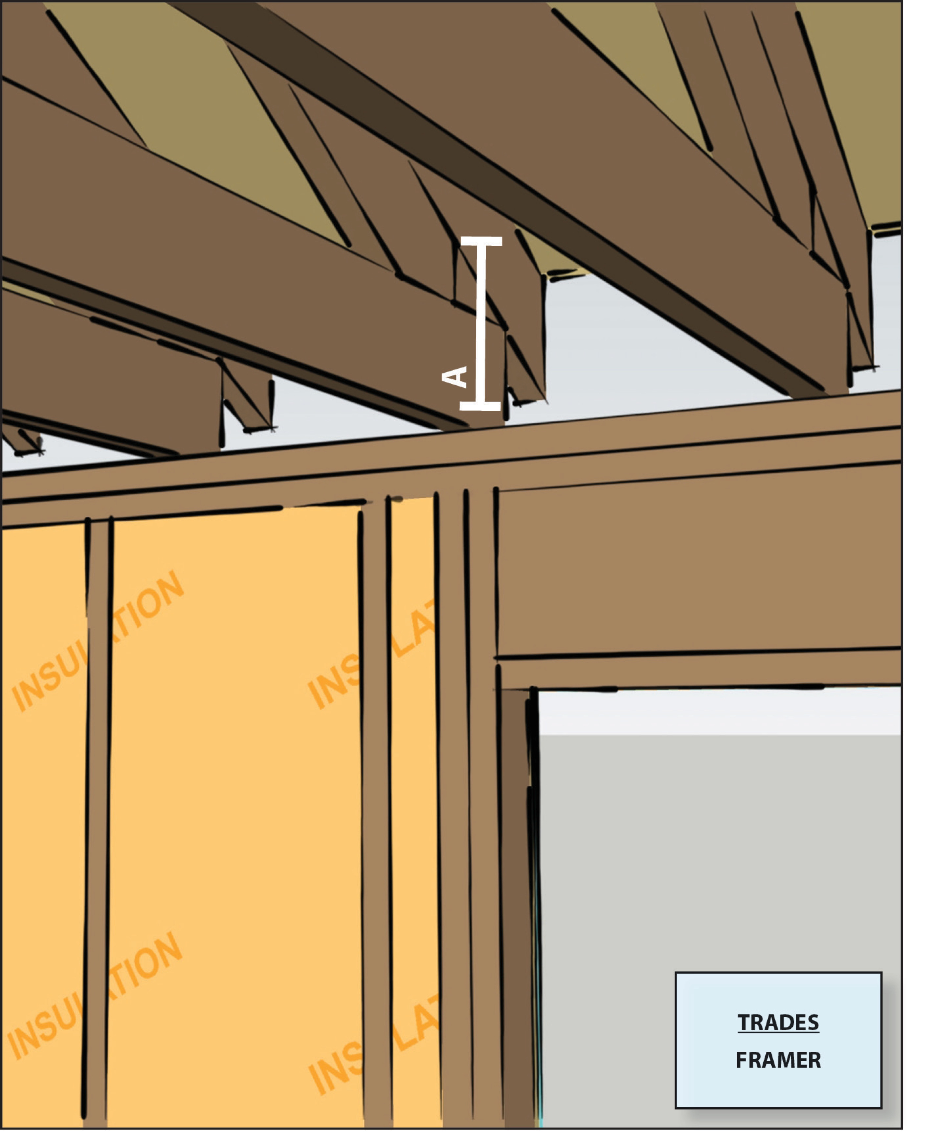
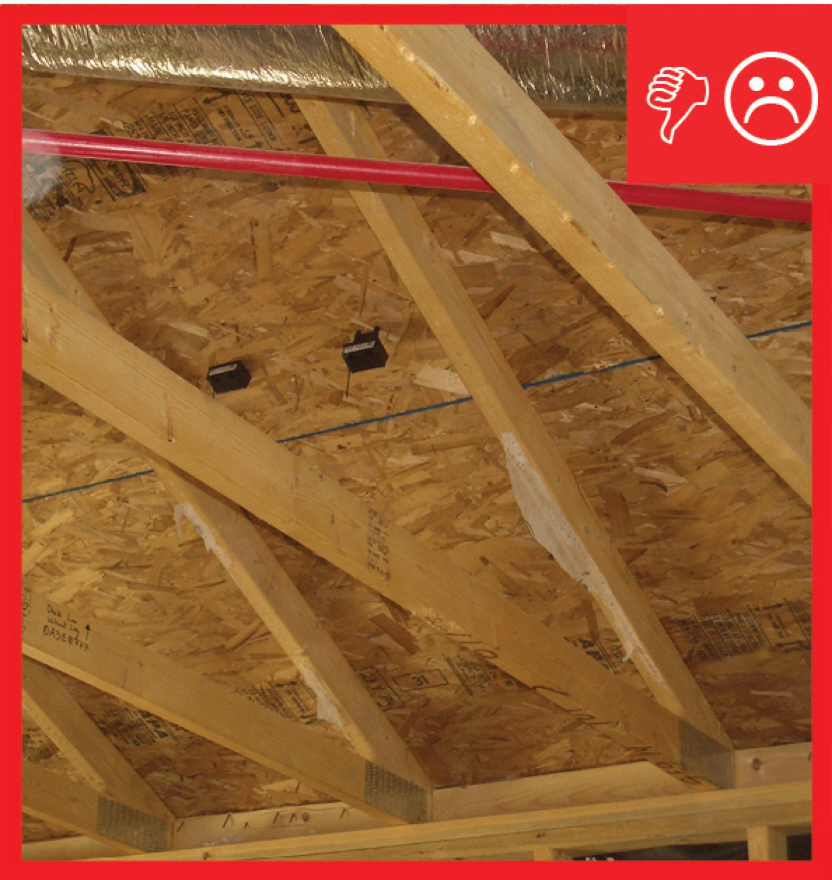
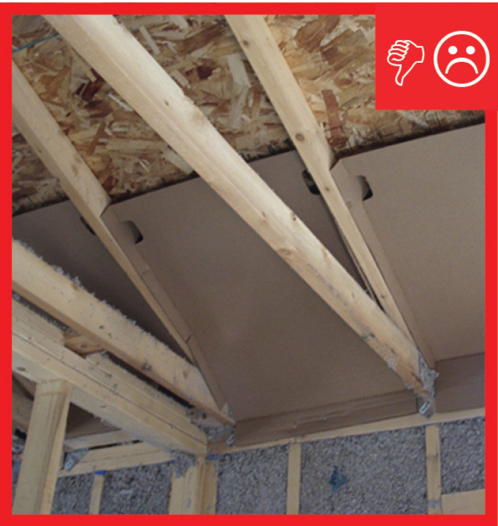
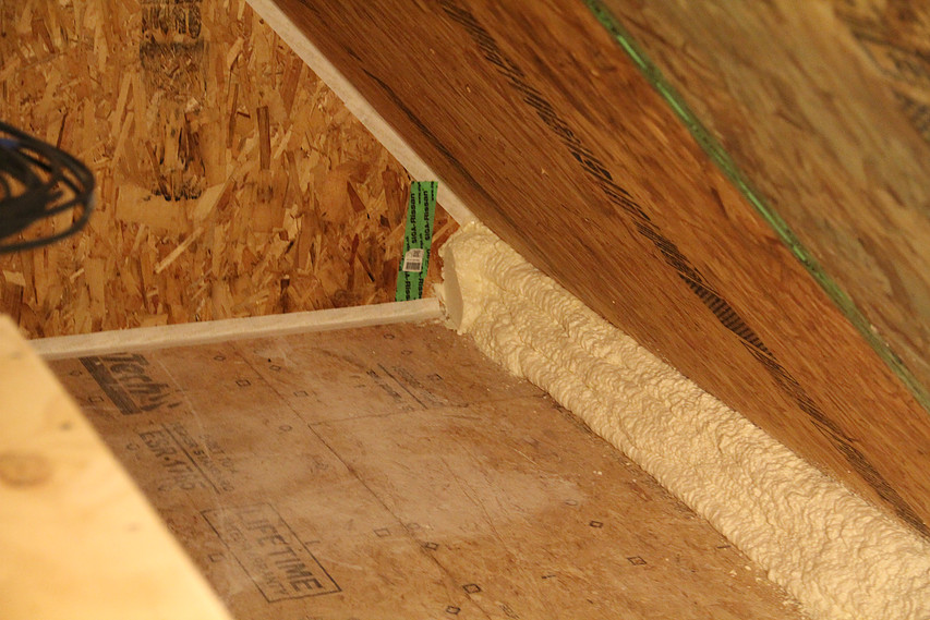
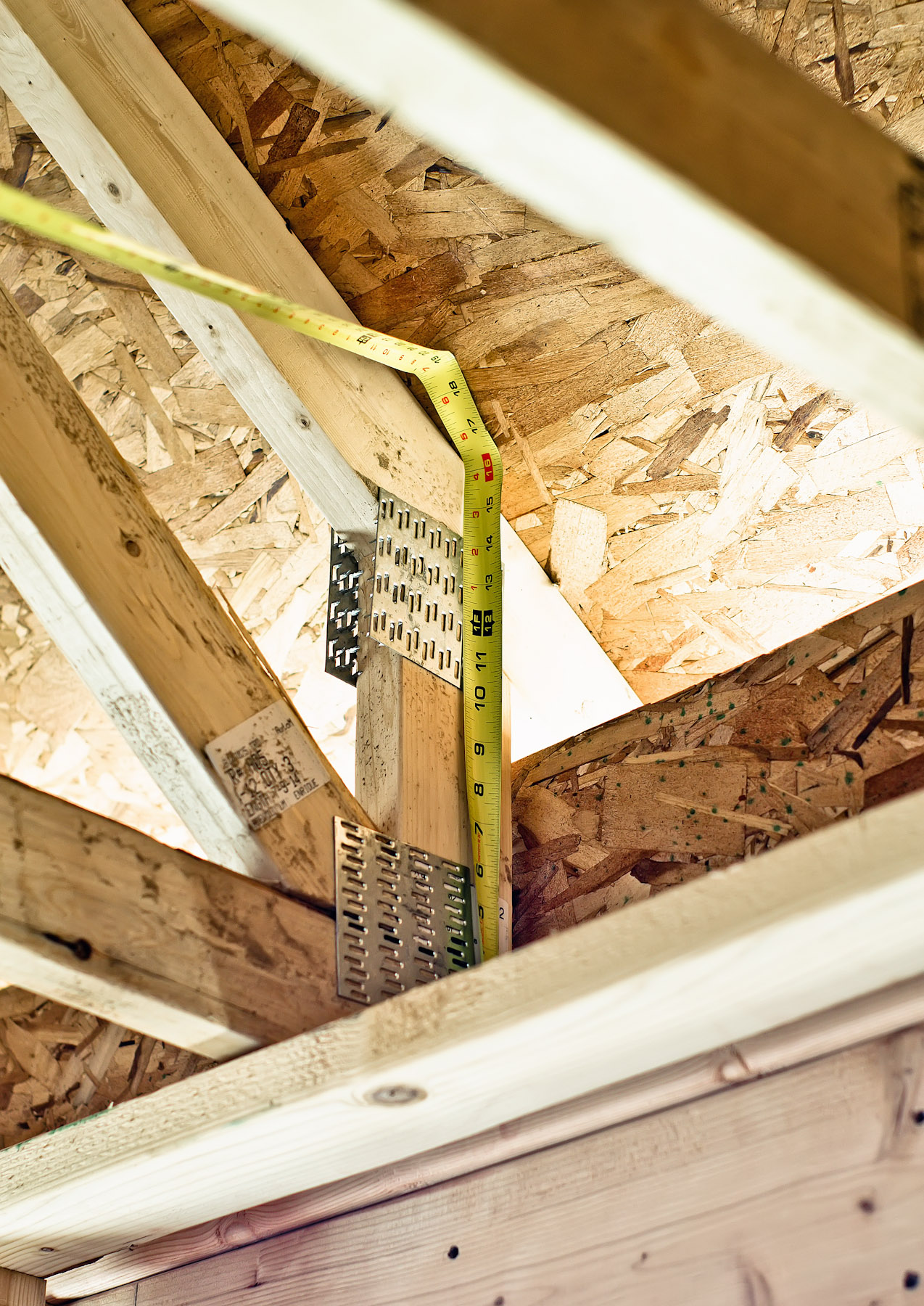
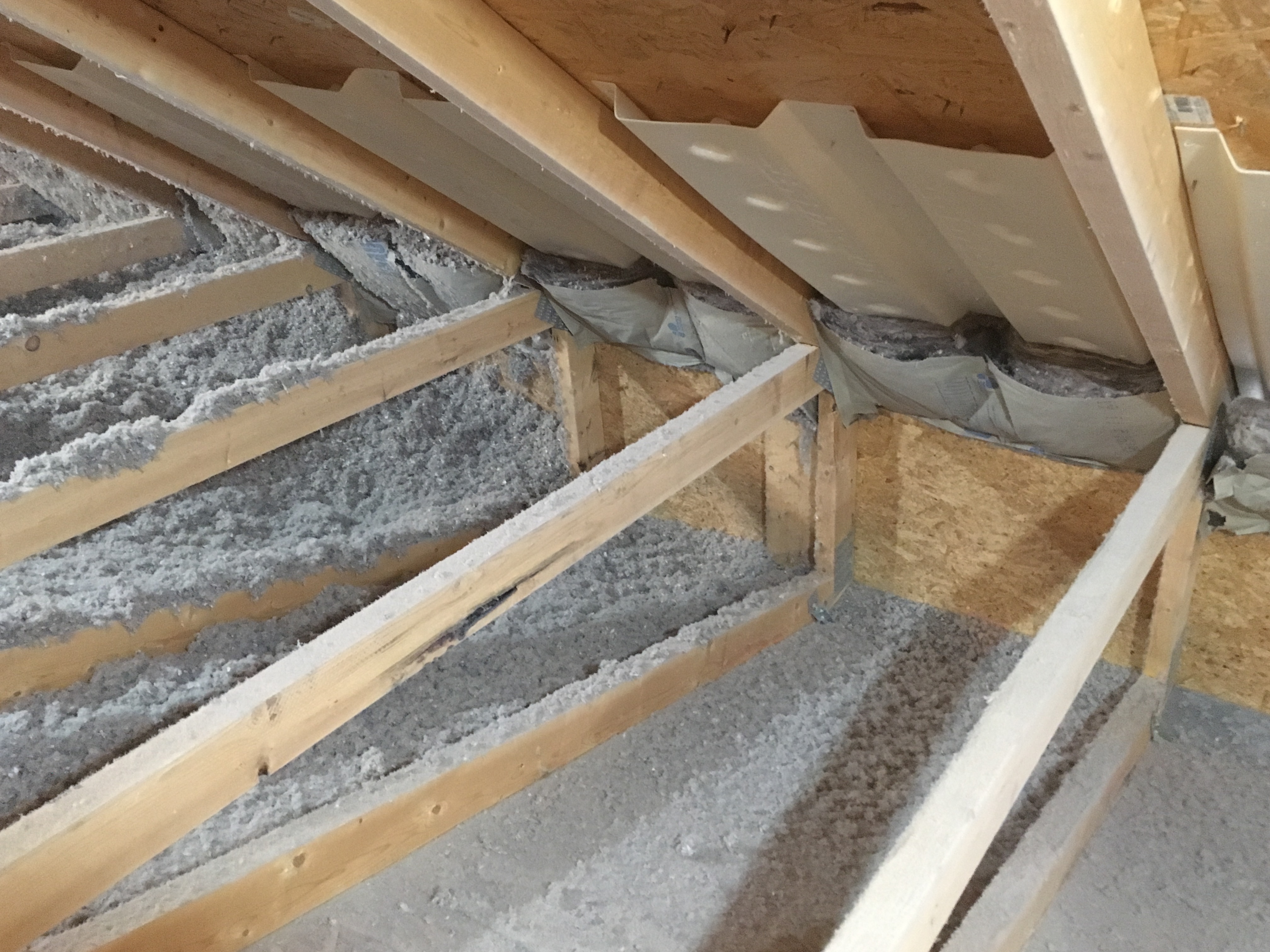
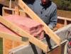
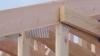
In vented attics, insulation is laid on the ceiling deck of the top floor of the home. Maintaining the insulation level throughout the entire plane of the ceiling and over the top of the perimeter walls is key to preventing heat flow through the ceiling and into or out of the home. At the attic eaves, insulation may be compressed or insufficient (Figure 1 and Figure 2). In the winter, this can cause cold spots along ceilings and subsequent condensation concerns. It can also create warm spots at the roof deck, which can cause snow melt and therefore contribute to ice dam formation in snowy climates. This can be true of roofs built with pre-made trusses and roof rafters constructed on site.
Source
Source
Builders and architects have several options for designing pitched, vented roofs that allow the insulation to achieve its full thickness over the plate line of the exterior walls:
- Elevating the heel (sometimes referred to as an energy truss, raised-heel truss, or Arkansas truss)
- Cantilevered or oversized trusses
- Lowering the ceiling joists
- Framing with a raised rafter plate
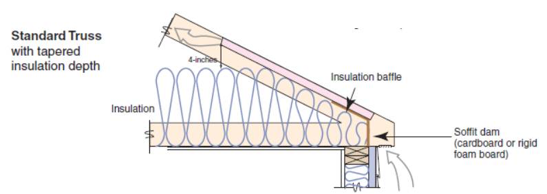
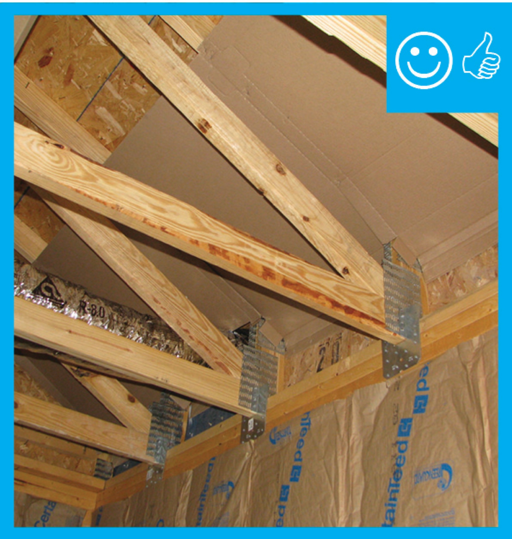
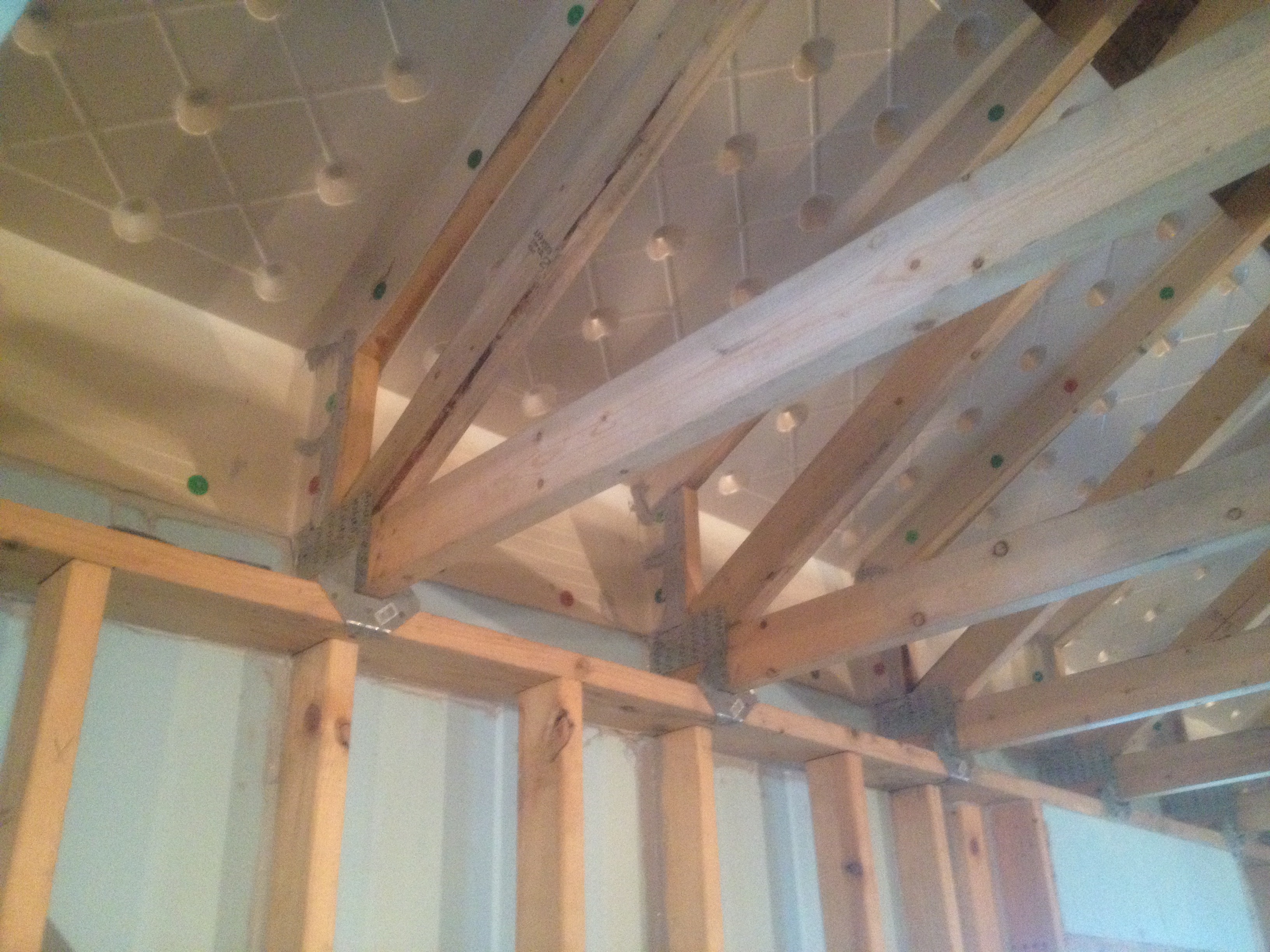
For truss roofs, raised heel energy trusses or oversized (cantilevered) trusses that form elevated overhangs, in combination with rafter baffles and soffit dams, will provide clearance for both full-height insulation and ventilation.
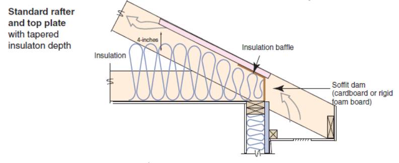
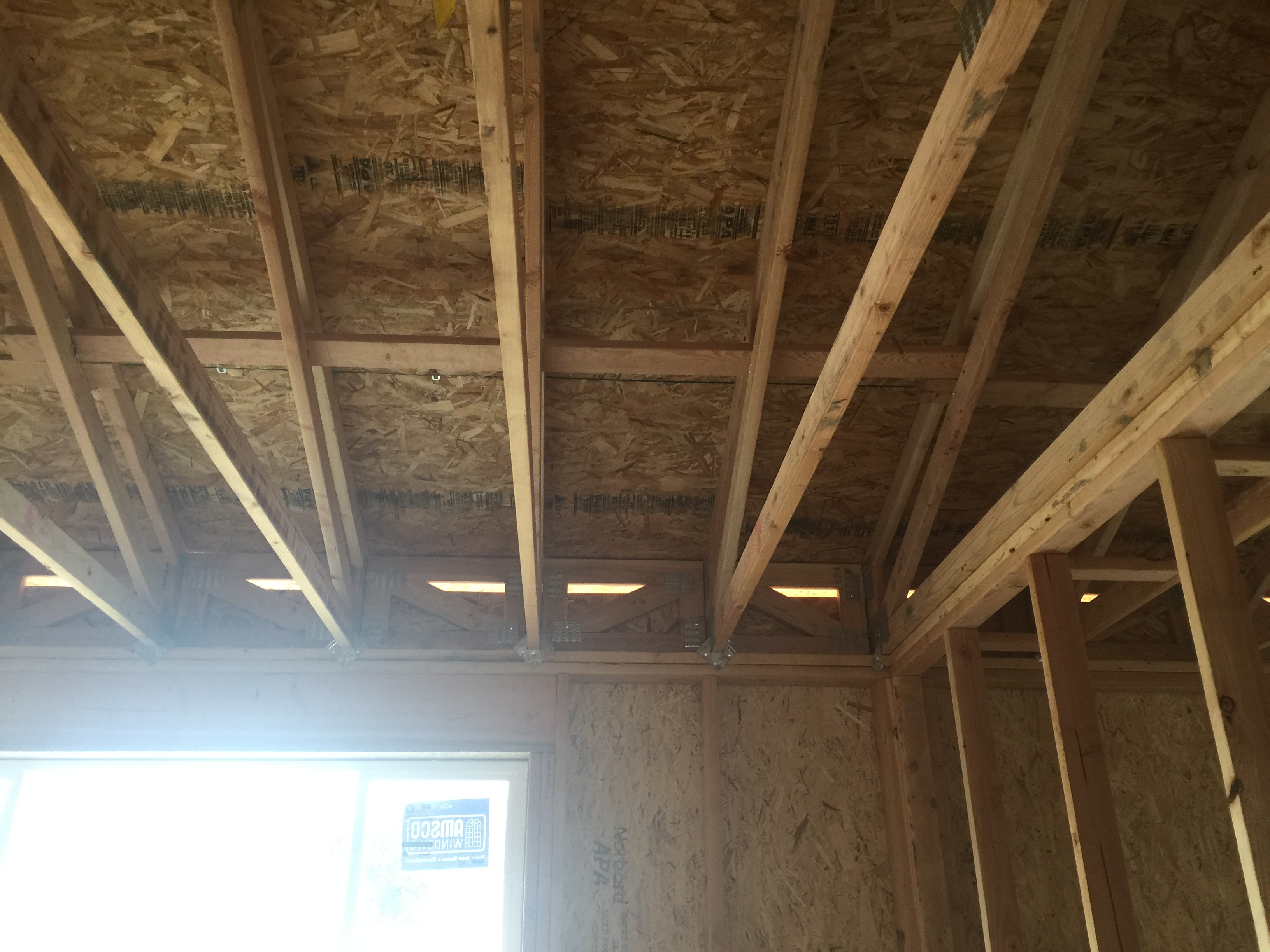
In stick-built roofs where rafters and ceiling joists are cut and installed at the construction site, laying an additional top plate across the top of the ceiling joists at the eave will raise the roof height, prevent compression of the attic insulation, and permit ventilation. When installing a raised top plate, place a band joist at the open joist cavities of the roof framing. The band joist also serves as a soffit dam, helping to prevent wind washing of the attic insulation (where air entering the soffit vents flows through the attic insulation, which can reduce attic insulation R-values on cold days or add moisture to the insulation) (Southface and ORNL 2000, Straube and Grin 2010).
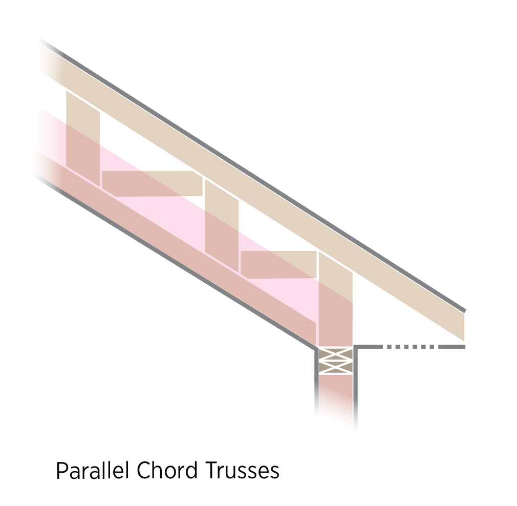
With a cathedral ceiling, a vaulted parallel chord truss roof can be constructed. Cathedral ceilings must provide space between the roof deck and ceiling for adequate insulation and ventilation. The residential provisions of the 2021 IECC require at least R-30 in areas where the roof-ceiling design doesn’t allow for more. Insulation levels of R-30 or higher can be achieved with truss joists, scissor truss framing, or sufficiently large rafters. For example, cathedral ceilings built with 2x12 rafters have space for standard 10-inch, R-30 batts and ventilation.
The designer should specify energy trusses or other constructions that will allow full height construction and baffles on building plans. These designs will be implemented by the framer. The insulation contractor should install the insulation correctly to full depth and install rulers. This task should be included in the contract for the appropriate trade, depending on the workflow at a specific job site.
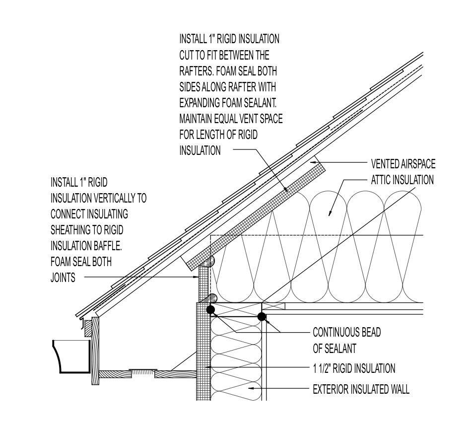
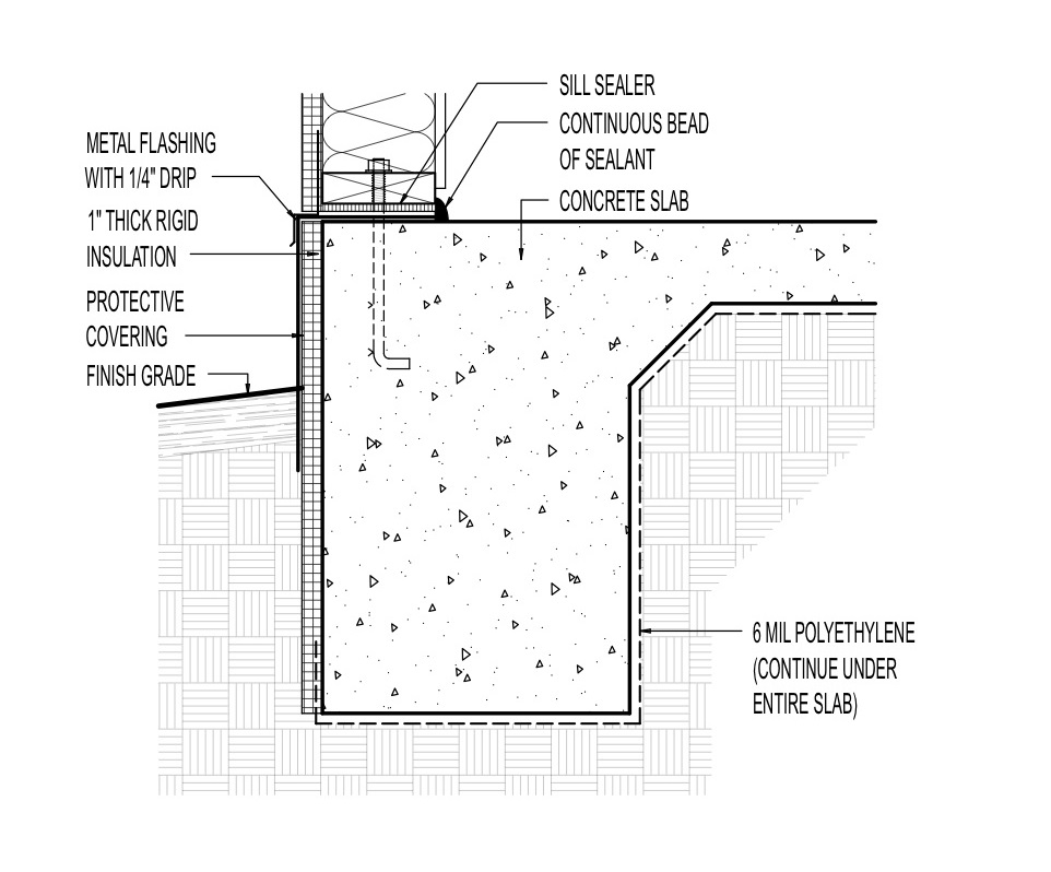
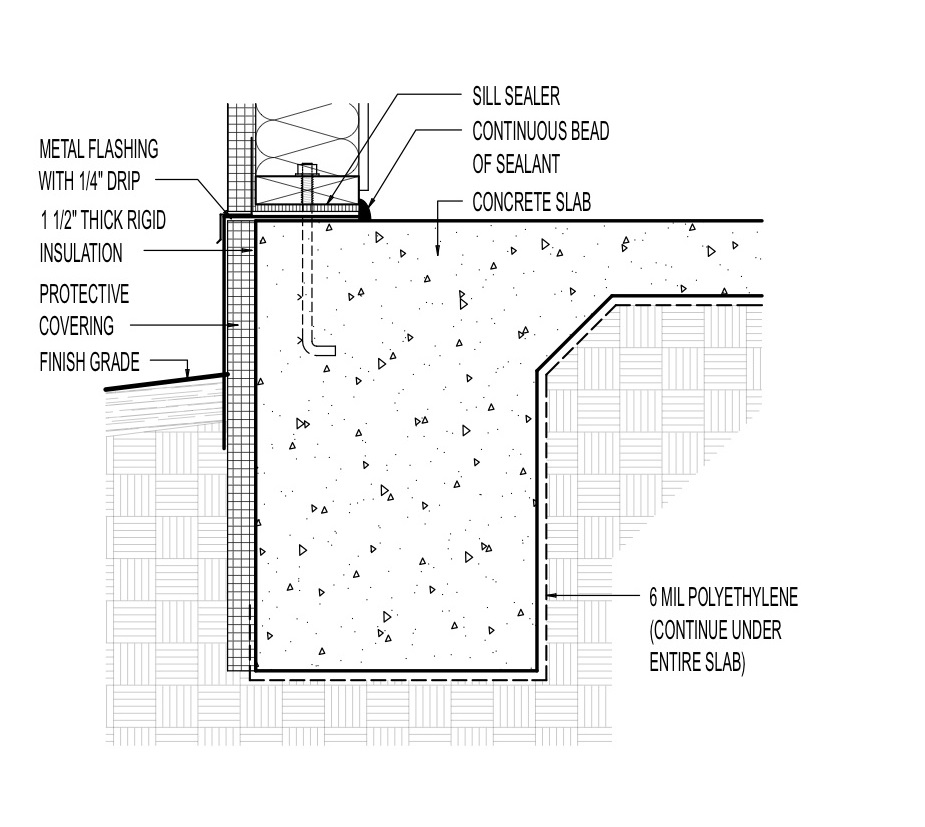
If the roof is designed with limited height over the exterior top plates, installing higher R-value per inch insulation over the top plates is an option. This could be rigid insulation that is R-5 or greater per inch, such as extruded polystyrene or polyisocyanurate, or closed-cell spray foam. Rigid foam block could also serve as the insulation dam and baffle to provide protection for soffit vents and ventilating air flow.
See the Compliance tab for IECC ceiling insulation requirements. Some building scientists note that fully vented, pitched attic assemblies can be the lowest cost, highest R-value, and most durable roofs in all climates zones (except perhaps IECC Zone 1 and Zone 2 with high coastal humidity), as long as no major sources of potential air leakage (e.g., HVAC ducts or recessed light fixtures) are present in the ceiling plane. Given the low cost, high insulation levels (R-60 to R-100) are affordable and economically justified in Zones 5 through 8. The only change required to meet these high insulation levels, other than an airtight ceiling, is to construct raised heel trusses or rafter designs to accommodate the increased amount of insulation (Straube and Grin 2010).
How to Construct a Roof with Full Insulation at the Eaves
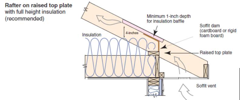
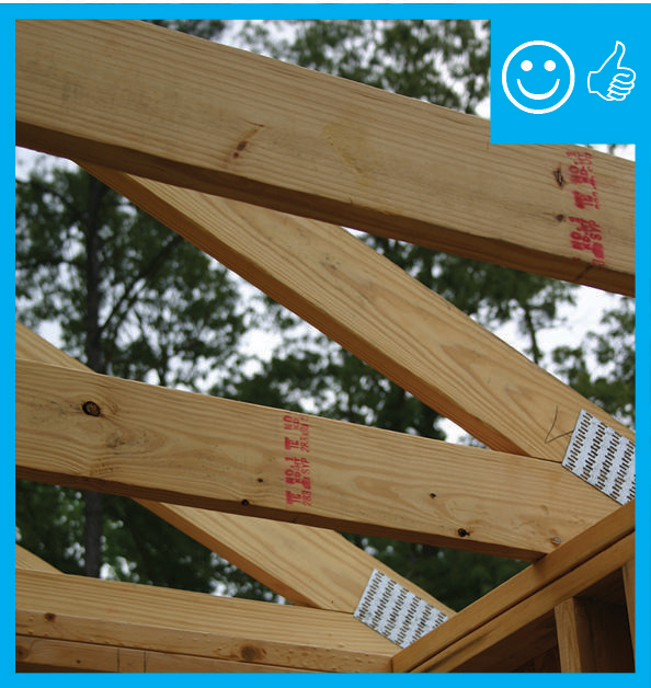
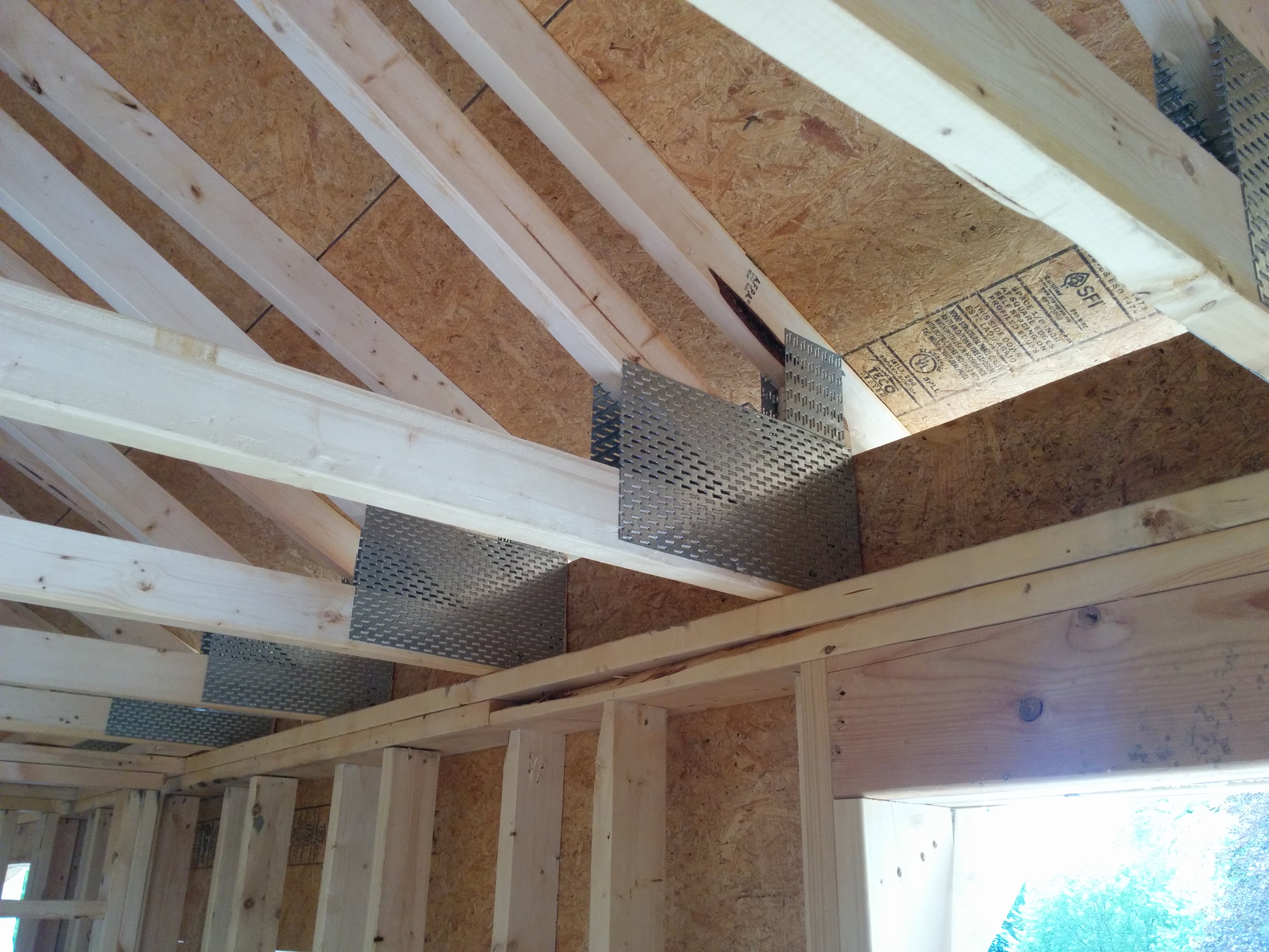
- Order and install oversized or raised heel trusses (Figure 3), or install site-built rafters with raised top plates (Figure 4). Specify 2- to 2½-foot overhangs, which are higher, providing more room for insulation at the top plate and additional window shading.
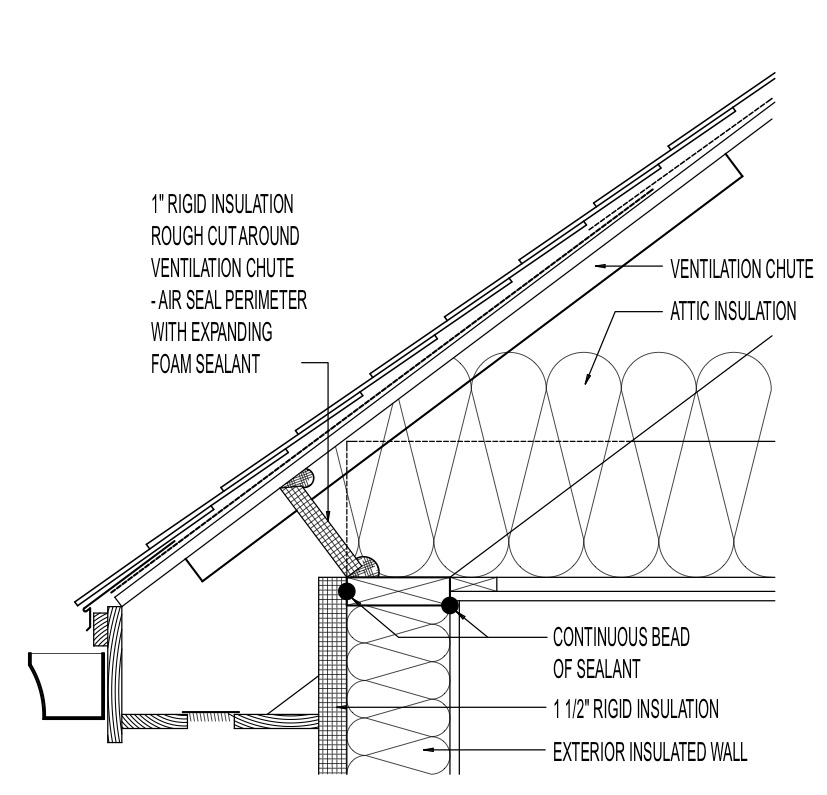
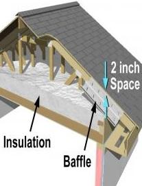
- Install baffles and soffit dams at each rafter bay to provide a clear path for ventilation air above the insulation and to prevent insulation from falling into the soffit vents.

Source
Source
3. For cathedral roofs, specify and install parallel chord trusses (Figure 5).
Source
- Install attic rulers to show that blown insulation is installed to the proper depth. (The rulers should be installed with numbering facing the attic entrance; one ruler for every 300 ft2).
- Fill the attic with blown, spray foam, or batt insulation to at least the required minimum insulation level. Blown or spray foam insulation should cover the tops of the ceiling joists. Batts should completely fill the joist cavities; an additional layer of batts can be placed on top of and running perpendicular to the joists. Shake batts to ensure proper loft. If joist spacing is uneven, fill any gaps with scrap pieces of insulation. Cut slits in batt insulation to fit around wiring, plumbing, or ductwork without compressions.
Ensuring Success
The quality of the insulation installation should be visually inspected by the site supervisor. It may be possible to detect heat loss at the tops of exterior walls with an infrared camera if a sufficient temperature difference exists between the outside and the conditioned space of the house. Attic rulers should be installed upright from the ceiling deck and facing the attic entrance, one ruler for every 300 ft2 including at the eaves, to make it easier for the inspector to confirm that proper insulation depth has been achieved.
Region
Hurricane and High Wind Zones
When engineered trusses are used with raised heels in regions designated as hurricane or high wind areas, blocking and continuous sheathing should be installed around the raised heel as bracing to resist displacement. Raised heel trusses have been found in laboratory testing to experience high top cord and rotational displacement compared to a low heel trusses during lab-simulated seismic events (NAHB Research Center 2011).
Cold Climate Zones
Adequate insulation and ventilation over exterior wall top plates is especially critical in colder climates with extended periods of snow cover or high snow loads, to reduce the risk of ice dam formation.
Insulation Requirements
The map in Figure 1 shows the climate zones for states that have adopted energy codes equivalent to the International Energy Conservation Code (IECC) 2009, 12, 15, and 18. The map in Figure 2 shows the climate zones for states that have adopted energy codes equivalent to the IECC 2021. Climate zone-specific requirements in the IECC are shown in the Compliance Tab of this guide.

Source
2012 edition of code establishing a baseline for energy efficiency by setting performance standards for the building envelope (defined as the boundary that separates heated/cooled air from unconditioned, outside air), mechanical systems, lighting systems and service water heating systems in homes and commercial businesses.

Source
2021 edition of code establishing a baseline for energy efficiency by setting performance standards for the building envelope (defined as the boundary that separates heated/cooled air from unconditioned, outside air), mechanical systems, lighting systems and service water heating systems in homes and commercial businesses.
Training
Right and Wrong Images
Source
Guide describing details that serve as a visual reference for each of the line items in the Thermal Enclosure System Rater Checklist.
Source
Guide describing details that serve as a visual reference for each of the line items in the Thermal Enclosure System Rater Checklist.
Source
Guide describing details that serve as a visual reference for each of the line items in the Thermal Enclosure System Rater Checklist.
Source
Guide describing details that serve as a visual reference for each of the line items in the Thermal Enclosure System Rater Checklist.
Source
Source
Source
Source
Source
Source
Videos
CAD Files


Compliance
Retrofit
SCOPE
Installing raised heel roof trusses, as described for new homes, is beyond the scope of most retrofits but energy performance of existing roofs can often be improved by adding air sealing, insulation and baffles.
- Provide a pathway for air to flow from soffit vents to the main part of the attic and up toward the ridge by installing or verifying installation of baffles.
- Prior to installing insulation, carefully clear, clean, and air seal the top plates along all exterior walls.
- Install insulation in the eave areas to the maximum height possible.
Assess the attic as described in the guide titled Pre-Retrofit Assessment of Attics, Ceilings, and Roofs. In ventilated attics, ensure there is adequate ventilation as described in the guide on Calculating Attic Passive Ventilation.
Air sealing can impact indoor air quality and the air available for combustion appliances to work properly. Before starting the air sealing read and conduct the assessments described in the Pre-Retrofit Assessment of Combustion Appliances and the Pre-Retrofit Assessment of Hazardous Materials.
The U.S. Department of Energy’s Standard Work Specifications (SWS) define minimum requirements to ensure that the work performed during home energy upgrades is effective, durable, and safe. The Standard Work Specifications include specifications for the following topics, which may be applicable to insulating soffits.
- Global worker safety.
- Worker health and safety specifications related to air sealing.
- General air sealing attics.
- Insulating attic ceilings.
- Soffit ventilation and baffles.
- Combustion safety, which may be impacted by air sealing.
DESCRIPTION
The techniques described in this guide for new homes require incorporating structural design features such raised heel trusses that allow for the full depth of insulation in the attic eaves. This approach is not feasible in existing homes that do not have specially designed roof trusses. However, attic eaves in existing home can be insulated to the extent that space allows while still permitting adequate ventilation.
Prior to installing insulation, carefully clear, clean, and air seal the top plates for all exterior walls. Clearing this area may involve rolling back or moving insulation that is in the rafter cavities. Use a continuous bead of sealant or spray foam to seal the seam between the top plate and the gypsum board. The seam may also be sealed with rigid foam, sheet goods, or reflective foil insulation that is glued in place and sealed along all edges. Seal all penetrations through the soffits that are not part of the air vents and confirm that screening over soffit vents is securely in place; these steps will help prevent the entry of pests and wind-blown rainwater.
Install baffles as described for new homes in the Description tab. In addition to the approach described for new homes, baffles may also be supported using spray foam or rolled fiberglass batts to form a backstop for the baffles. If the baffles will block access to the wall top plate, seal the top plate before installing the baffle.
Completely fill the space between the attic floor and the attic-side of the baffles with blown-in, batt, or spray-foam insulation. Use insulating material with the highest R-value to achieve the best success in the limited space. Spray foam has the advantage of combining air-sealing with insulation and will conform well to the sloping contour of the roof and the complex shape of the rafters.
For more information on related topics see the following guides.
Batt Insulation for Existing Vented Attics
Guide describing how to increase insulation in existing homes by installing batt insulation on the ceiling plane of a vented attic.
Blown Insulation for Existing Vented Attic
Guide describing how to insulate a vented attic in an existing home using blown insulation added to the attic floor.
Ducts Buried in Attic Insulation
Guide describing burying ducts in loose-fill attic insulation, a method that can only be used in dry climates.
Guide describing wind washing and how to prevent it.
SUCCESS
Before insulating the attic floor, clear, clean, and air seal the top plates where all interior walls intersect the attic floor.
COMPLIANCE
See Compliance tab.
More Info
References and Resources
*For non-dated media, such as websites, the date listed is the date accessed.
Contributors to this Guide
The following authors and organizations contributed to the content in this Guide.
Sales
High-R Attic Insulation = High-Efficiency or Ultra-Efficient Attic Insulation
Technical Description
There are two levels of attic insulation: high-efficiency insulation, which meets the 2015 International Energy Conservation Code, and ultra-efficient insulation, which is 25% more efficient than this national code. Using high-efficiency and ultra-efficient insulation along with professional installation (e.g., no gaps, voids, compression, or misalignment with air barriers; complete air barriers; and minimal thermal bridging) creates conditioned spaces that require very little heating and cooling, along with even comfort and quiet throughout the house.
Questions? Comments? Contact our webmaster.