

Scope

Determine whether to locate the thermal boundary at the roof line or at the ceiling plane of a home.
This decision will be based on several factors, including:
- climate
- desire for additional living and storage space
- building design and configuration
- location of HVAC.
See the Compliance Tab for links to related codes and standards and voluntary federal energy-efficiency program requirements.
Description
Where to locate the thermal boundary is an important design consideration when designing the roof-attic-ceiling assemblies in new construction. The thermal boundary consists of the thermal barrier (insulation) and the air barrier (for example, caulked sheathing or mudded and taped drywall). These two layers should both be continuous around the building envelope (walls, ceiling, floor), and they should be in continuous contact with each other.
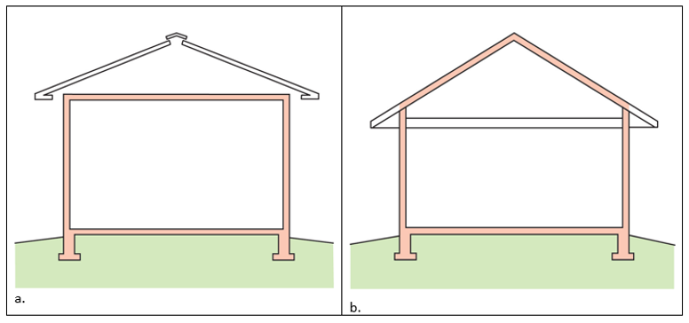
In a roof-attic assembly, the builder has two choices: the thermal boundary can be at the ceiling plane, leaving the attic space above uninsulated and vented, or the thermal boundary can be located at the roof line, creating a sealed, insulated, conditioned or semi-conditioned attic space. When the thermal barrier is located at the roof line, it can be either above or below the roof decking. Either way, the attic would be unvented.
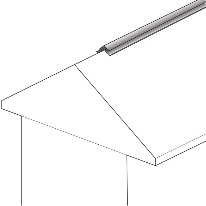
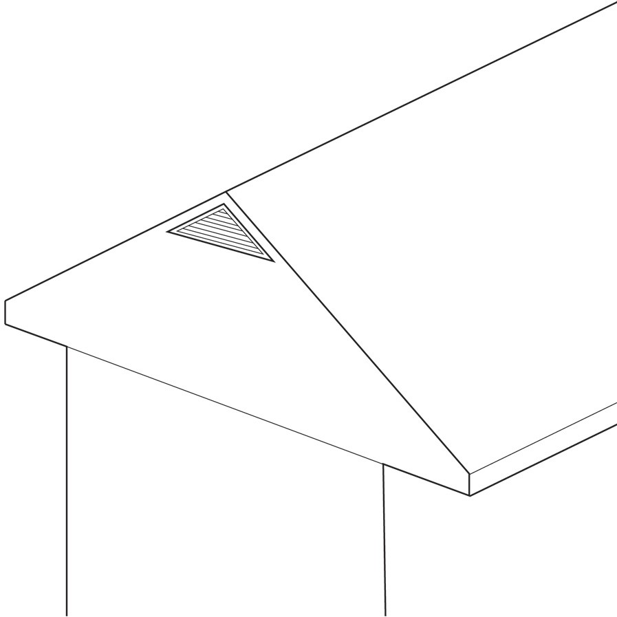
See Figures 1 through 3 for examples of thermal boundary locations for vented and unvented attics for three attic designs: flat ceiling/gable roof, low-sloped shed roof, and 1-and ½-story home.

Vented Attics
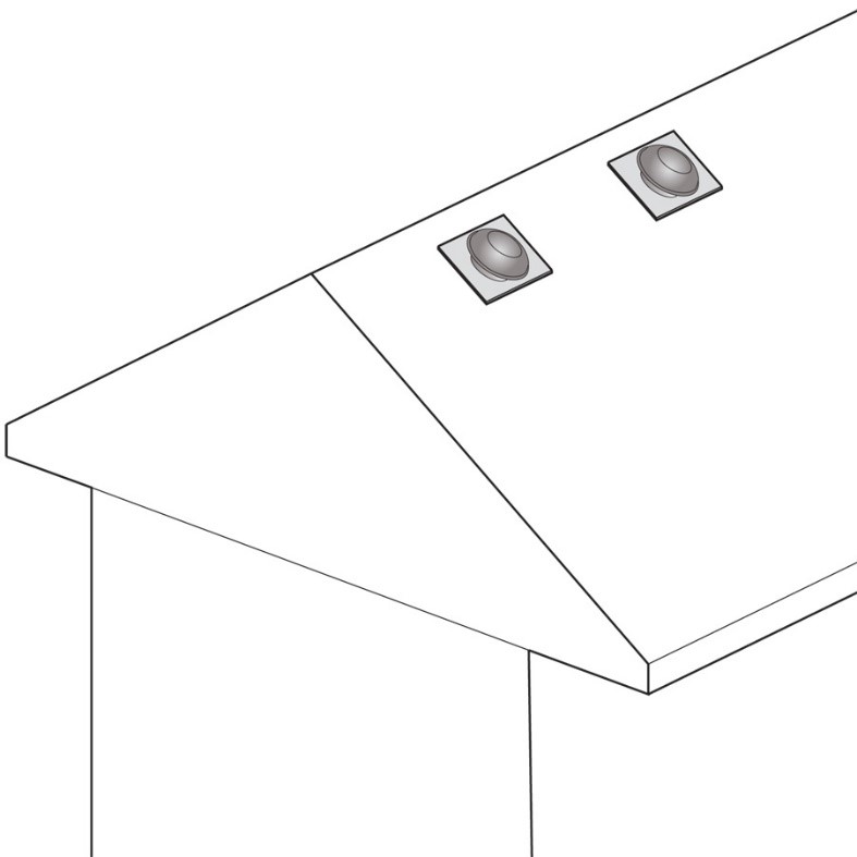
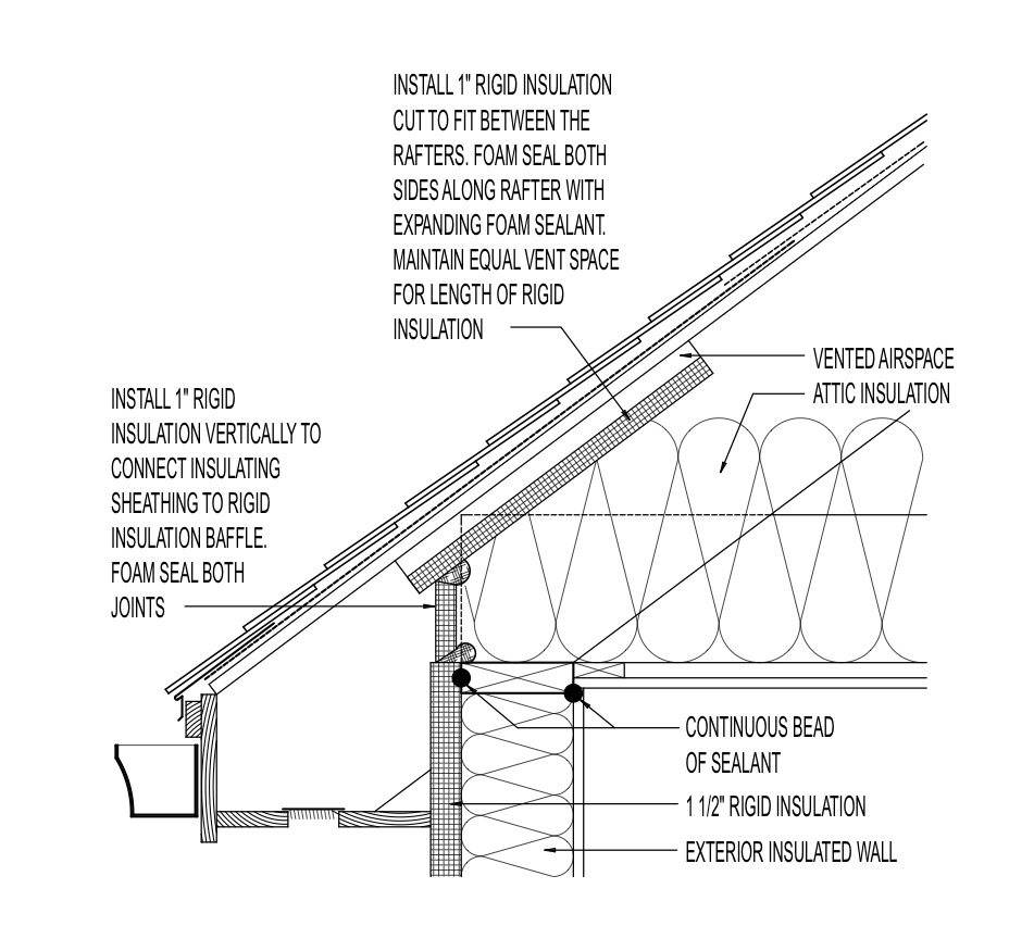
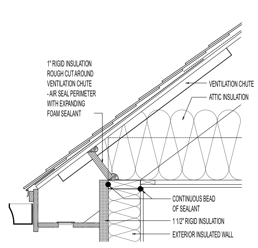
When the thermal boundary is at the ceiling level, the ceiling drywall serves as the air barrier; any gaps around penetrations (for wiring, flues, ducts, etc.) are carefully air sealed. The thermal barrier consists of the insulation (typically blown fiberglass or cellulose, sometimes spray foam and batt), which is piled on top of the ceiling drywall. Vents are installed at the soffits and at or near the ridge, and baffles are installed at each soffit vent to provide a pathway for ventilation air from the soffit to the ridge and to keep insulation from blocking the soffit vents. The lower soffit vents are intended to "supply" air to the attic space, and the upper roof/attic vents are intended to "exhaust" air from the attic space. Ridge vents are more effective than off-ridge vents such as "mushroom" or "button" vents in this regard. In general, gable-end vents should not be used in conjunction with a ridge or off-ridge vents because the gable-end vents are likely to "short-circuit" attic air flow.
In hurricane and high-wind locations and fire-prone locations, the IBHS Fortified Home program recommends not installing gable-end vents in new homes. Use certified, properly installed ridge or off-ridge vents rather than gable vents. For existing homes that have gable vents, either permanently block the gable vents or provide removable or operable exterior or interior coverings or shutters that can be installed when a hurricane or fire threatens and removed when the threat has passed. Permanent mounting anchors should be installed for these coverings. To provide more robust wildfire resiliency, mesh screening should be installed at soffit vent openings. The recommended mesh size is 1/8 inch (3 mm) or less. Ridge vents that are compliant with Miami-Dade wind-driven rain requirements and are effective at wind-driven rain control are also effective in controlling the entry of airborne embers or cinders.
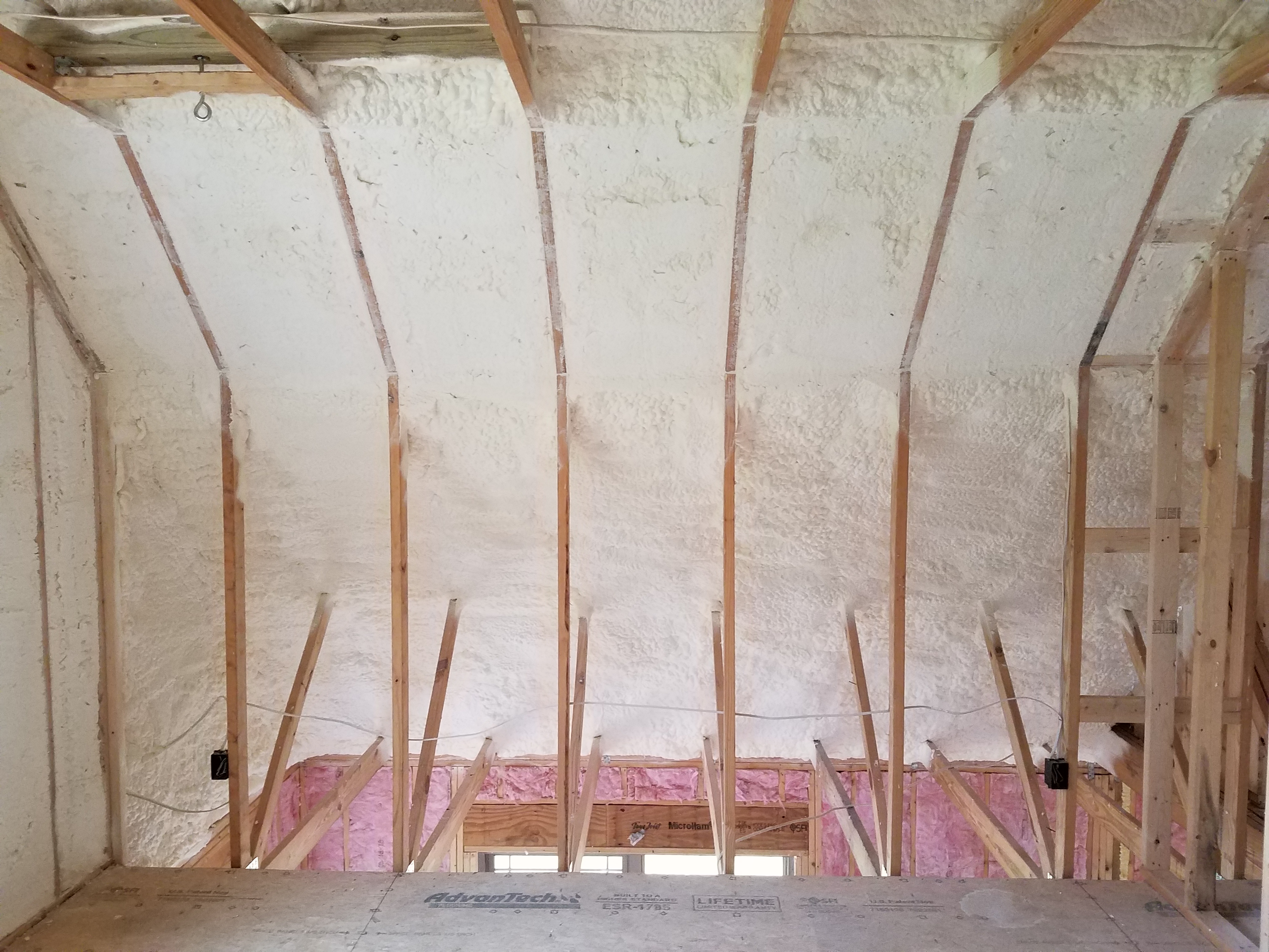
Unvented Attics
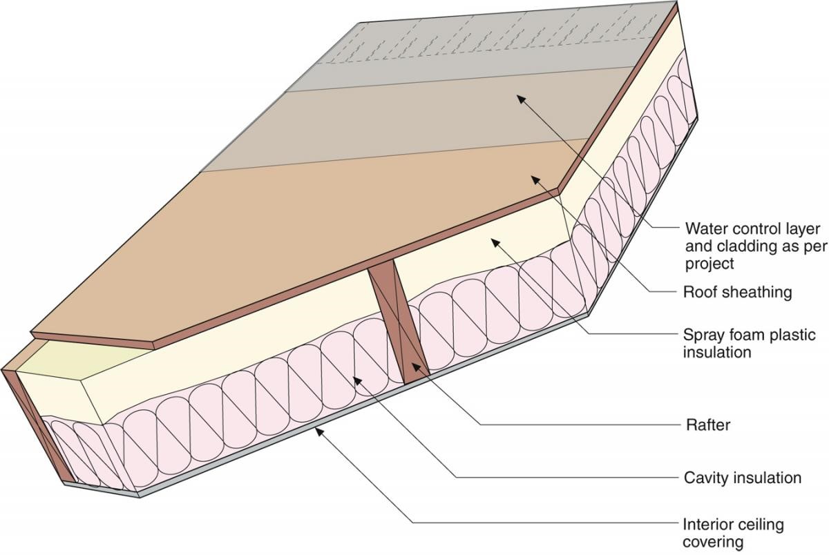
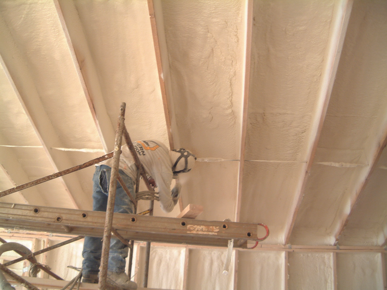
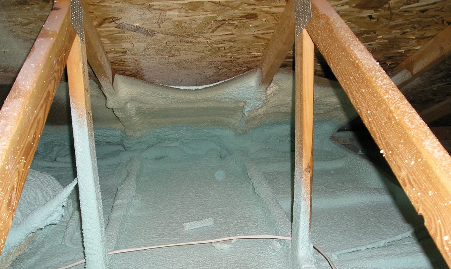
The key to creating an unvented roof assembly is to keep the roof deck – the principle condensing surface in roof assemblies – sufficiently warm throughout the year such that condensation will not occur or to prevent interior moisture-laden air from accessing the roof deck. This is done by using air-impermeable insulation such as rigid foam board or spray foam. Rigid foam insulating sheathing is installed on top of the roof sheathing. For more information on this technique, see the guide Above Deck Rigid Foam Insulation for Existing Roofs. Spray foam is installed on the underside of the roof sheathing. For more information on this technique, see the guide Spray Foam Under Roof Sheathing. Both methods require a very high degree of airtightness for the avoidance of condensation due to the warming of cold surfaces. For the above-deck rigid foam, air tightness is achieved by installing a continuous membrane over the roof sheathing and under the rigid foam. This membrane could be a peel-and-stick or paint-on membrane or a carefully installed underlayment. For below-deck insulation, the spray foam will provide condensation control. However, all wood-to-wood joints in the framing must still be sealed. In both assemblies, air-permeable insulation (such as batt or loose fill) can be used to increase the overall insulation value. For the above-deck rigid foam option, the batt or blown insulation would go below the decking. The minimum required thickness of the "air-impermeable insulation" to manage condensation potential is stated in Table R806.5, "Insulation for Condensation Control," of the 2012 IRC. For cold climates, the air-impermeable insulation should be maintained at 50% or more of the total R-value of the roof system for condensation control. For example, if an R-80 unvented cathedralized attic is to be constructed in a cold climate, a minimum of R-40 (50%) should be air-impermeable insulation installed and layered according to Section R806.5 of the 2012 IRC (Figure 4). See the IRC or the guide Unvented Attic Insulation for details.
Choosing between a Vented and Unvented Attic
Factors to consider when determining where to locate the thermal barrier in new construction include cost, climate, desire for additional living and storage space, building design and configuration, and location of HVAC. Some factors are listed below. See the Retrofit tab for additional factors that should be considered in existing homes.
Vented attics are generally less expensive than unvented attics. There are three reasons for this. First, the types of insulation appropriate for insulating an attic floor (blown-in cellulose or fiberglass) tend to be less expensive than the types of insulation appropriate for insulating a roof and gable walls (spray foam or rigid foam board). Second, less insulation is required because the area being insulated is smaller. Finally, installation at the attic floor is often faster and less complex.
Depending on house geometry, an unvented attic can have 10% to 60% more square feet of surface area needing insulation than a vented attic. This larger area is due to the fact that the total area of a sloped roof plus gable and dormer walls is greater than the area of the attic floor. This directly affects not only cost, but also the efficiency of the home. All else being equal, an envelope assembly with 10% to 60% more area will have 10% to 60% more heat losses and gains, resulting in more load on the HVAC system.
Vented attics can reduce heat gains to the conditioned space by ventilating and exhausting heat from the attic. The insulation on an attic floor is essentially "shaded" from the sun by the roof above it. Attics, though hot in summer, are not as hot as the roof above them. Vented attics also allow fairly simple installation of radiant barriers.
While a vented attic has the advantages of less surface area and the ability to exhaust heat, the performance of the insulation itself can be much poorer than that of an unvented attic. Because the insulation in a vented attic is typically loose-fill insulation, it is susceptible to settling. This can result in a significant loss of R-value. Additionally, the fact that the loose-fill insulation in vented attics is open at its upper surface invites heat loss and gain through convection, especially in winter. Any movement of air through insulation greatly reduces its effectiveness. Air-sealing details can also be more challenging in a vented attic than an unvented attic due in part to more penetrations such as lighting, electrical wiring, and ductwork. Finally, if HVAC equipment is located in the attic, an unvented assembly will be much more efficient because the ductwork and air handler will be inside the thermal envelope. Ultimately, which type of attic assembly is more efficient depends on several factors including the difference in surface area, the effectiveness of any attic ventilation, the presence of a radiant barrier, the presence of a cool roof, the degradation of insulating ability through settling and open convection, the effectiveness of air-sealing details, and whether or not HVAC equipment is located in the attic.
A vented attic insulated at the attic floor makes it easier to detect and solve roof leaks or other moisture-related issues. If a leak does occur, moisture damage is less likely because the exposed and ventilated rafters and decking can dry out more readily. The underside of the roof decking and the rafters or top chords of the trusses are relatively easy to access compared to an unvented assembly where the decking and rafters might be encased in spray foam or sandwiched between the roof and the ceiling material (in the case of a cathedralized ceiling).
However, unvented attics have several advantages over vented attics. In coastal locations, hurricane regions, and areas prone to wildfires, it may be advisable to construct an unvented conditioned attic because soffit and roof vents can be an entry point for wind-blown rain and burning embers as well as salt-laden air which can corrode fasteners and HVAC equipment. Eliminating vents can also reduce the likelihood of entry into the attic by insects, rodents, birds, and other pests.
Other reasons for constructing an unvented attic include the following. The builder (or homebuyer if the buyer has purchased prior to construction) may want the attic space to be conditioned for additional living or storage space. The home design may have a complex interior design that would require many transitions between flat ceilings, knee walls, trey ceilings, and/or vaulted ceilings; in cases where numerous transitions make it difficult to achieve a continuous thermal barrier at the ceiling, it may be simpler and thus less expensive to insulate at the roof line.
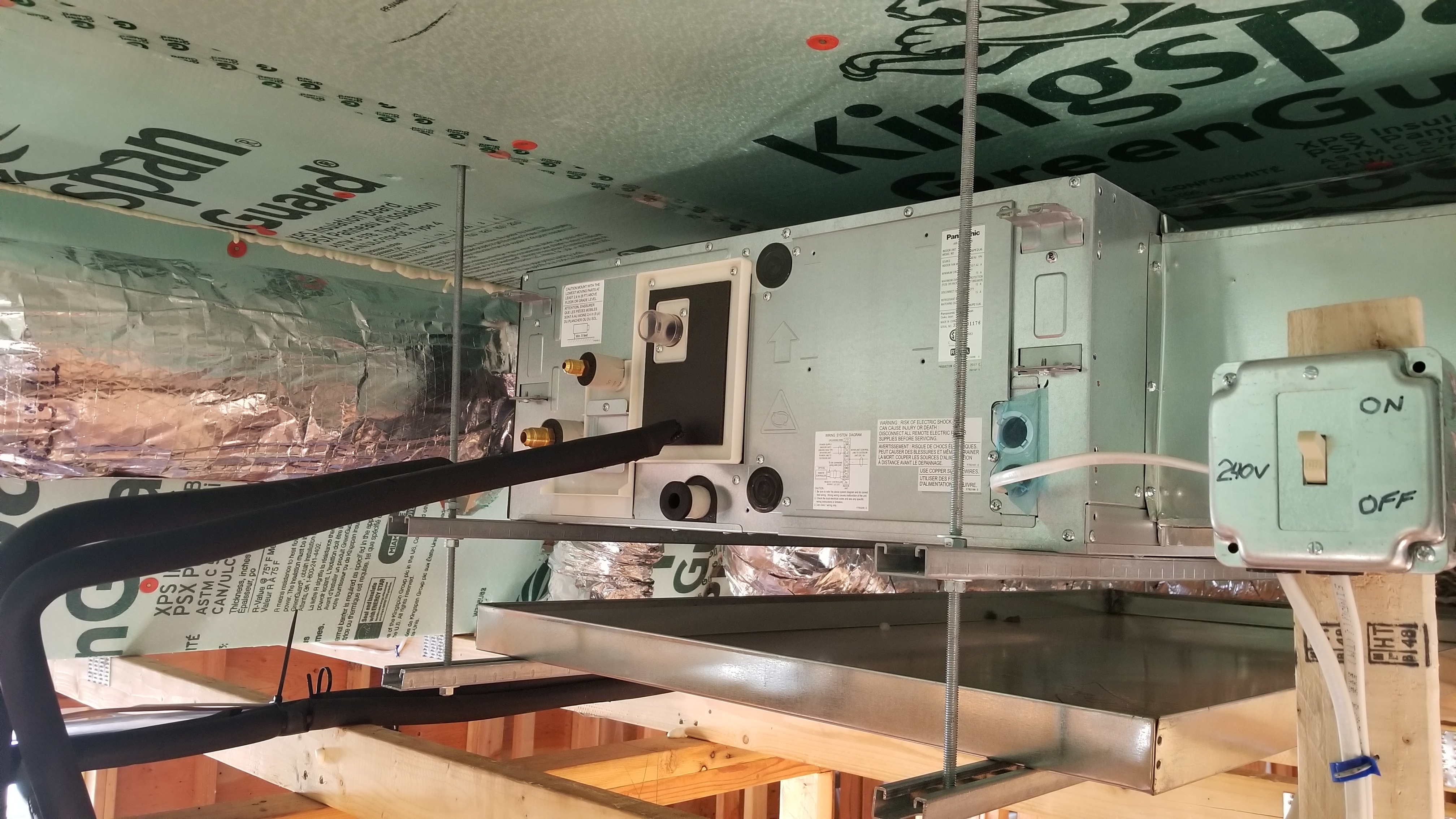
A design decision to have a central ducted heating and cooling system with ducts and/or air handler located in the attic is another good reason to insulate and air seal at the roof line, as this will provide a conditioned or semi-conditioned space for the HVAC equipment. This can improve HVAC performance and longevity because the equipment does not have to work against the much greater temperature differentials of a vented attic. If HVAC is located in the attic, the energy efficiency advantages of using an unvented attic assembly will likely outweigh the energy losses through increased insulation area.
For installation guidance for vented and unvented attics in new and existing homes, see these Building America Solution Center guides. For more information, search “attics” or “roofs” in the Solution Center:
- Unvented Attic Insulation
- Attic Eave Minimum Insulation
- Attic Kneewalls
- Insulation Below Attic Platforms
- Blown Insulation for Existing Vented Attic
- Batt Insulation for Existing Vented Attics
- Spray Foam Insulation Applied to Existing Attic Floor
- Below Deck Spray Foam Insulation for Existing Roofs
- Application of Spray Foam Insulation Under Plywood and OSB Roof Sheathing
- Above Deck Rigid Foam Insulation for Existing Roofs
- Disaster-Resistant Roof Venting
Ensuring Success
Vented attics are less expensive to insulate, have less heat transfer area between inside and outside, are easier to retrofit for energy efficiency, make roof leak detection simpler, and are easier to fix if moisture damage occurs. Unvented attics can provide more resistance against wind pressures and wind-driven rain in high-wind regions and protection against wind-borne embers in wildfire-prone areas. They can also provide an insulated space for storage and HVAC equipment. Climate, homeowner desires, and subcontractor skill levels may dictate which option to choose.
The key to creating an unvented roof assembly is to keep the roof deck – the principal condensing surface in roof assemblies – sufficiently warm throughout the year such that condensation will not occur or to prevent moisture-laden air from the interior of the home from accessing the underside of the roof deck. The roof deck can be kept warm by installing rigid foam insulation over the sheathing. For more information on this technique, see the guide Above Deck Rigid Foam Insulation for Existing Roofs. Or, interior moist air can be kept from reaching the underside of the roof deck by covering the underside of the roof sheathing with air-impermeable insulation like closed-cell spray foam. For more information on this technique, see the guide Below Deck Spray Foam Insulation for Existing Roofs. Both methods require a very high degree of airtightness to avoid condensation. For the above-deck rigid foam, air tightness is achieved by installing a continuous membrane over the roof sheathing and under the rigid foam. This membrane could be a peel-and-stick or paint-on membrane or a carefully installed underlayment. For below-deck insulation, the spray foam will provide condensation control. However, all wood-to-wood joints in the framing must still be sealed.
Region
In coastal locations, hurricane regions, and areas prone to wildfires, it may be advisable to construct an unvented attic because soffit vents, roof vents, and gable vents can be entry points for wind-blown rain, burning embers, and salt-laden air that can corrode HVAC and fasteners. If the home is constructed with a vented attic, specify vents that are high wind and fire-resistant.
In hot, humid locations, it may also be advisable to construct unvented rather than vented attics to help reduce the entry of moisture-laden air into the attic. In hot, humid locations, the outside air is likely to be more humid than the inside air. Inside surfaces may be cooler and may provide condensing surfaces for humid air introduced into a vented attic, thus encouraging condensation in the attic.
There are climate-specific criteria for attic insulation requirements and impermeable insulation requirements for unvented attics. See the Compliance Tab for specific criteria.
Training
Right and Wrong Images
Source
Source

Source

Source

Source
Source
Source
Article describing how insulating and air sealing unfinished attic spaces can lead to reduced energy bills in some homes.
Source
Source
Source
Source
Videos


CAD Files

Compliance
Retrofit
Scope
Consider occupant use, performance, and building geometry factors when determining whether to retrofit an existing attic to provide insulation and air sealing at the roof line rather than the attic floor.
- See the Scope and Description tabs for more information and links to installation guides.
- See the U.S. Department of Energy’s Standard Work Specifications for more on attic insulation retrofits.
- See the guide Pre-Retrofit Assessment of Attics, Ceilings, and Roofs for more on safe work practices when working in attics.
Description
In existing homes, attics are typically vented and may or may not have any insulation (See Figure 1). Options for retrofit include blowing in more insulation at the attic floor, improving attic ventilation, installing a radiant barrier, or turning the attic into unvented space and insulating at the roof line and gable walls. In determining whether or not to seal the attic and insulate it at the roof line, there are several factors to consider. Some of these factors are listed below.
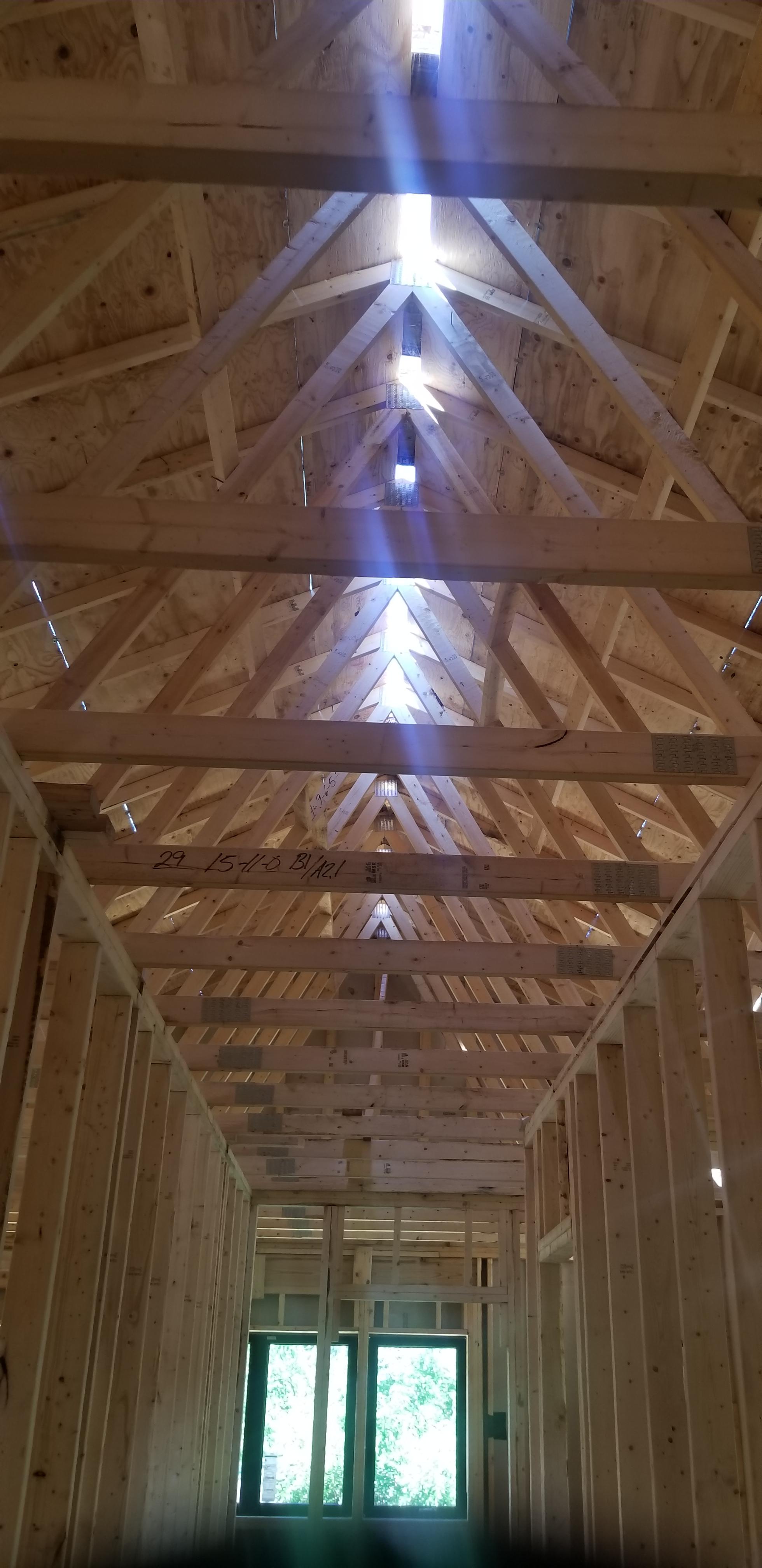
- Is the roof supported by truss framing? If yes, it can’t be used for living space, which argues for attic floor insulation.
- Is the HVAC equipment in the attic? If yes, it should be sealed and insulated at the roof line, even if the roof uses truss framing.
- Are there already rooms in the attic that are used for living space? If yes, then the simplest way to ensure a continuous air and thermal boundary is likely to insulate at the roof line.
- Is the attic used for a significant amount of storage? If there is a desire to make that space conditioned to protect stored belongings, if moving everything out to air seal and insulate at the attic floor would be a hassle, and/or if insulating at the attic floor would remove storage space, then insulating at the roof line is a better option.
- Is there a staircase leading to the attic?
- Is there flooring over the attic floor? If existing flooring is located perpendicular to the ridge and attached to the framing, it may have been installed to resist roof thrust. Consult a structural engineer before removing. Removal would be the best way to adequately air-seal the attic floor, so moving the air and thermal boundary to the roof line is the better option.
- Is there a lot of dust and debris on the attic floor? Hazardous materials must be removed, and surfaces must be cleaned, regardless of which option is chosen.
- Does the attic have a very low slope that limits the ability to adequately air seal, insulate and provide 2 inches of ventilation space above the insulation from the eaves to ridge vents? If yes, then insulating at the roof line may be the better way to ensure adequate R-value.

Ensuring Success
Important Health and Safety Prerequisites for High-Performance Enclosure Retrofits
Changes to the building enclosure will have a significant impact on the dynamics of water, air, vapor, and heat flow within the home. Certain measures should be implemented to ensure that these changing dynamics do not have negative ramifications for health and safety. It is also important to ensure that parts of the building not directly affected by the work are able to support and protect the planned work. Prior to upgrading to the thermal enclosure,
- Ensure combustion safety for combustion equipment located within the pressure boundary.
- Remediate any hazardous conditions that will be affected (e.g., exposed or aggravated) by the planned work.
- Ensure that the roof system provides robust protection from rainwater and ice dams and that proper flashing is in place (might be concurrent with an upgrade if replacing the roof is a part of the planned work).
- Provide mechanical ventilation if not already provided.
Combustion Safety
Provide minimum combustion safety by providing direct-vent sealed-combustion equipment or forced draft equipment (see Direct Vent Equipment). When furnaces, boilers, and water heaters are installed within the home’s pressure boundary, ideally, this equipment would be direct-vent sealed-combustion equipment. If existing equipment is not direct-vent sealed-combustion or forced draft, the homeowners must decide whether to
- Replace equipment with a direct vent or forced draft equipment, or
- Retrofit forced-draft to existing equipment.
Hazardous Materials
Hazardous materials that will be affected by the retrofit work or that may impact the indoor air quality must be remediated and/or removed. Follow applicable laws and industry procedures for the mitigation of hazardous materials. Engage the services of a qualified professional when needed.
Roof Condition
Except where a roof replacement is planned, ensure that the existing roof system provides robust protection from rainwater and ice dams (see the guides Step and Kick-Out Flashing at Roof-Wall Intersections and Roof Eaves Sealed with Self-Adhering Membrane in Cold Climates). A structural evaluation may be needed to determine if the roof is capable of supporting expected snow loads above a high R-value attic/roof assembly.
Ventilation
Provide mechanical ventilation complying with current local codes. Mechanical ventilation may be added concurrently with or as part of the larger attic/roof retrofit project.
Compliance
Section 101.4.3 Additions, alterations, renovations, or repairs. Portions of an existing building that are altered in the course of additions, alterations, renovations, or repairs must be brought into conformance with the code with the following exceptions applicable to attic/roof retrofit: existing ceiling wall or floor cavities that are exposed provided the cavities exposed are filled with insulation; addition, alteration, renovation or repair projects that do not expose the existing roof, wall or floor cavity; reroofing that does not expose the insulation nor the sheathing.
Section 101.4.5 Change in space conditioning. This section states that spaces must be brought into full compliance with the new construction requirements if the addition, alteration, renovation, or repair changes that space from unconditioned to conditioned space.
Section R101.4.3 Additions, alterations, renovations, or repairs. Portions of an existing building that are altered in the course of additions, alterations, renovations, or repairs must be brought into conformance with the code with the following exceptions apply to attic/roof retrofit: existing ceiling wall or floor cavities that are exposed provided the cavities exposed are filled with insulation; addition, alteration, renovation or repair projects that do not expose the existing roof, wall or floor cavity; reroofing that does not expose the insulation nor the sheathing.
Section R101.4.5 Change in space conditioning. This section states that spaces must be brought into full compliance with the new construction requirements if the addition, alteration, renovation, or repair changes that space from unconditioned to conditioned space.
Appendix J, Section 501.6, Ventilation. This appendix is not attached to the requirements of the IRC unless it is specifically included by the adopting jurisdiction. This section of the appendix indicates that any space that is changed to be habitable or occupiable by alteration must be provided with ventilation in accordance with Section R303.
More Info
References and Resources
*For non-dated media, such as websites, the date listed is the date accessed.
Contributors to this Guide
The following authors and organizations contributed to the content in this Guide.
Sales
High-Performance Thermal Enclosure = High-Performance Thermal Enclosure
Questions? Comments? Contact our webmaster.