

Scope
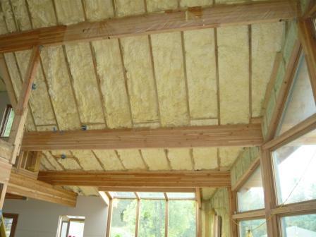
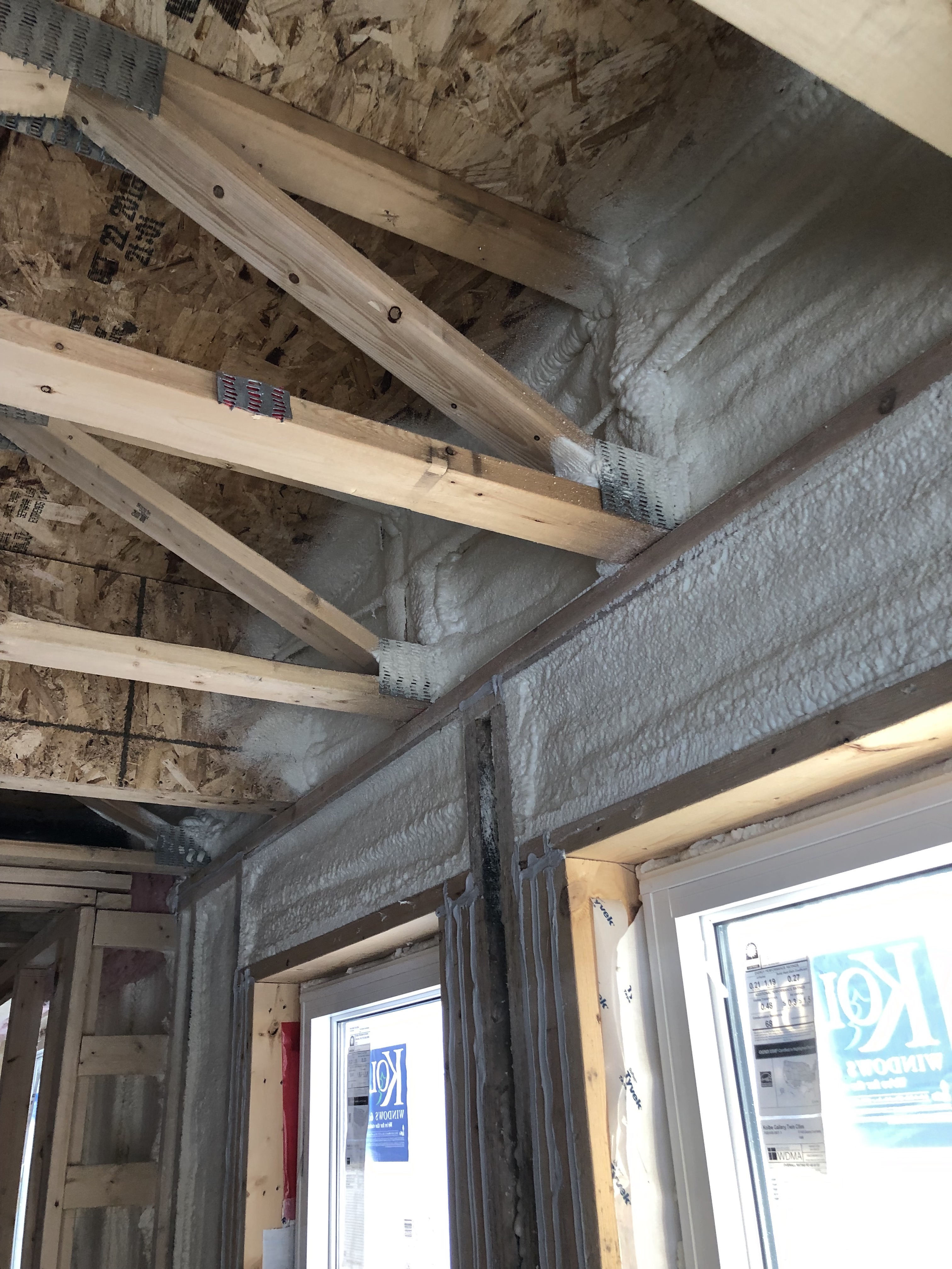
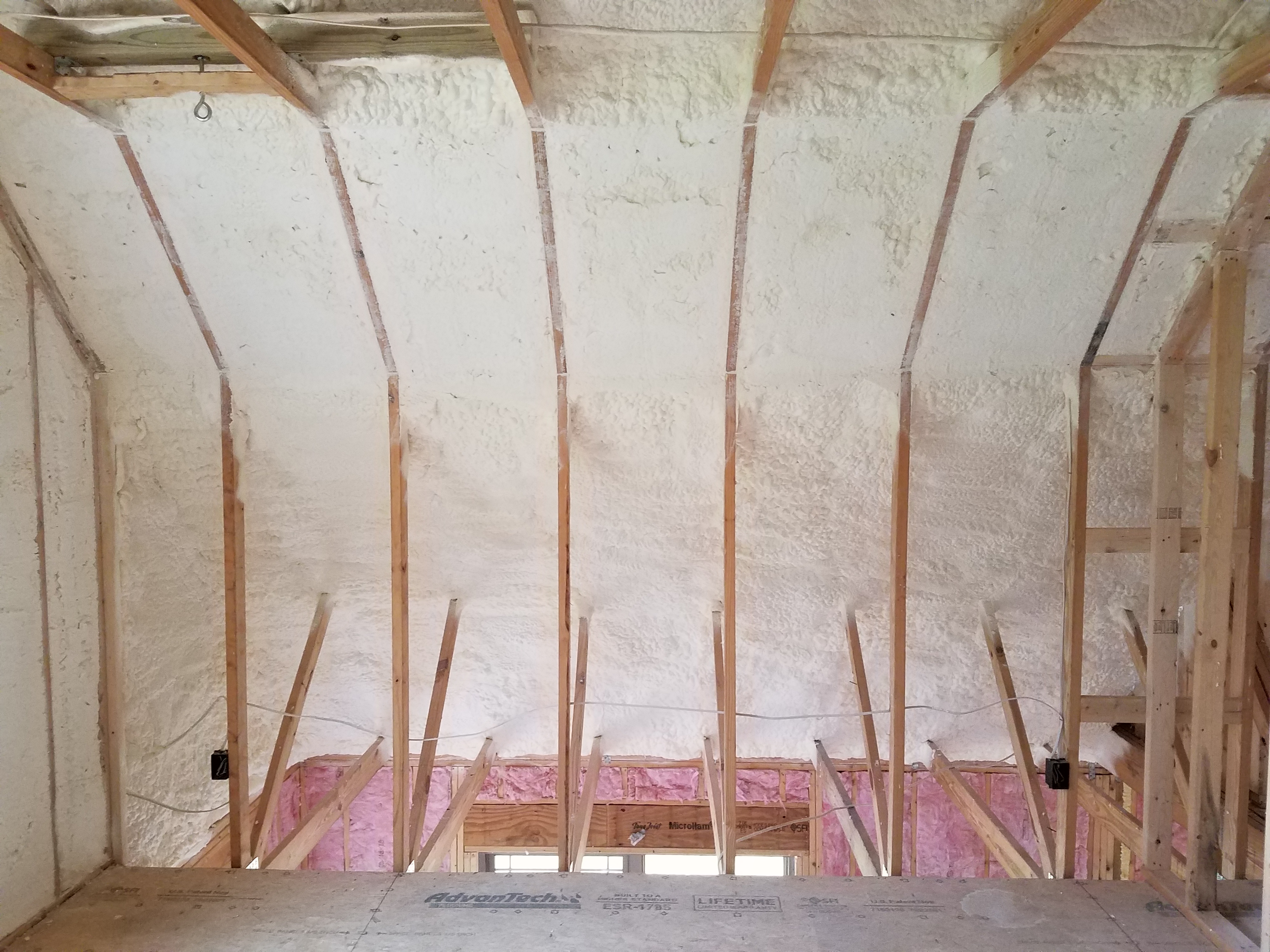
Insulate the attic or roof of a new home by installing spray polyurethane foam insulation - either open cell or closed cell - on the underside of the roof deck.
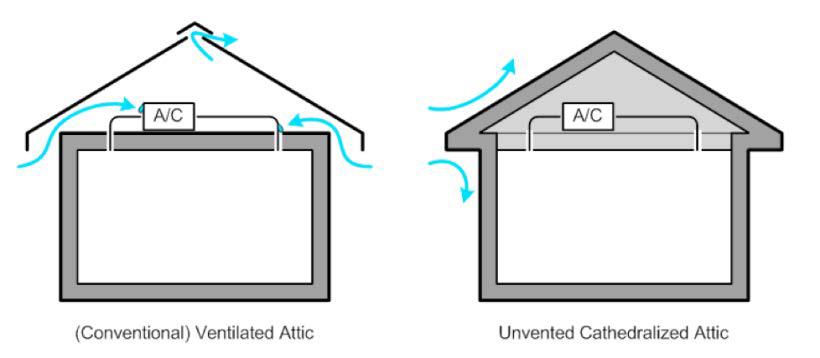
- Design and construct a roof /attic assembly with no vents.
- Install spray polyurethane foam insulation (and additional insulation other than spray polyurethane foam if desired) in the roof cavity to levels that meet or exceed the current adopted building and energy codes.
- Install thermal or ignition barrier (coating, gypsum board, or other material) over spray polyurethane foam insulation if necessary based on the material properties of the spray polyurethane foam or as required by code. Note that not all spray polyurethane foams require thermal or ignition barriers.
- Seal any penetrations from the home into the attic through the attic floor.
- Provide conditioning, dehumidification, or controlled ventilation to the attic.
- Ensure the home has good ventilation.
See the Compliance Tab for links to related codes and standards and voluntary federal energy-efficiency program requirements.
Description
Unvented conditioned attics and roofs with spray foam insulation applied to the underside of the roof deck have been used since the mid-1990s. Open-cell spray polyurethane foam (ocSPF) or closed-cell spray polyurethane foam (ccSPF) insulation is sprayed along the underside of the roof sheathing to provide an unvented insulated and conditioned attic space or roof assembly that can be resilient, durable, and efficient in all climate zones. Unvented insulated attics can provide a tempered space for HVAC equipment, conditioned storage space, and living space (habitable space) within the conditioned boundary of the building enclosure (“thermal envelope”).
Unvented conditioned attics and roofs are significantly more “fire safe” in wildfire areas and where neighboring buildings are close. Ash and embers enter vented attics through attic vents. No vents means no ash or embers entering attics and much less risk of fire.
In high wind regions – particularly in coastal areas – wind-driven rain is a problem with vented attics and vented roof assemblies. Additionally, during high-wind events, vented soffits have been known to collapse, leading to building pressurization and window blowout and roof loss due to increased uplift. Unvented conditioned attics and roofs are safer during hurricanes; they outperform vented attics and roofs, principally due to the robustness of their soffit construction
In coastal areas, salt spray and corrosion are a major concern with steel frames, metal roof trusses, and truss plate connectors in vented attics and vented roofs. This is not an issue with unvented conditioned attics and roofs.
In flood-prone areas, provision should be provided to allow access to roof tops if refuge, rescue, and evacuation becomes necessary. This can be provided by installing operable skylights or dormers or other alternatives that allow egress.
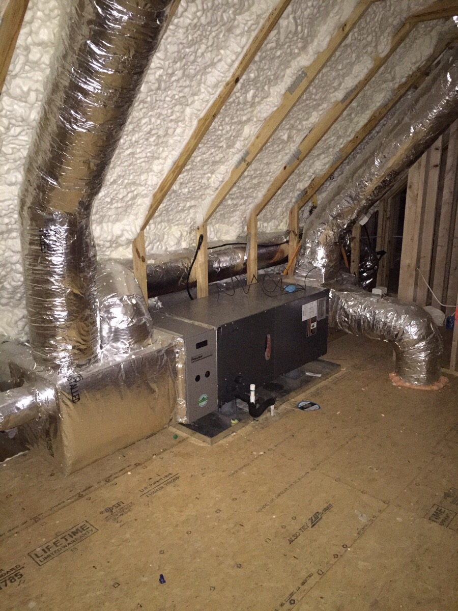
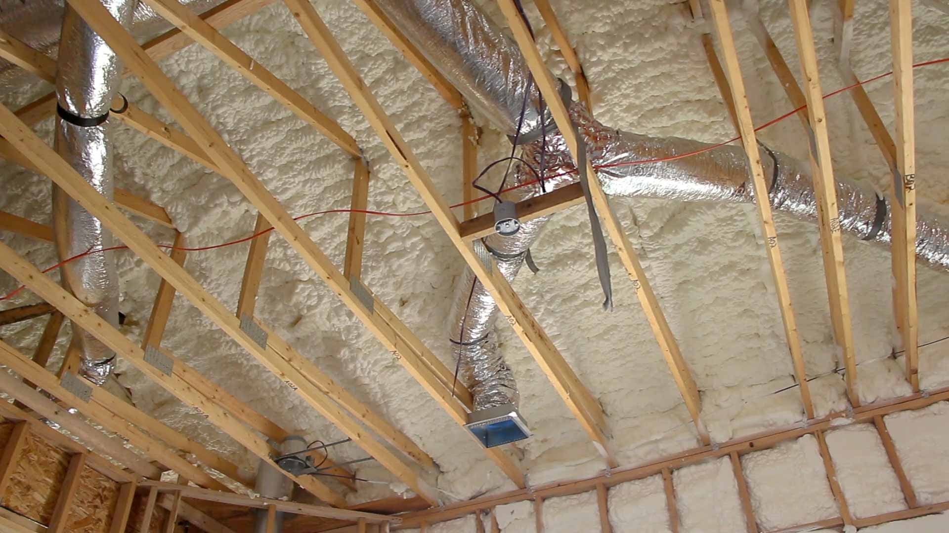
Moving the air control layer and thermal control layer to the underside of the roof deck has significant advantages in cases where the HVAC system is located in the attic; by locating HVAC equipment and ducts within the thermal envelope of the home, conductive thermal losses are minimized and any losses due to air leaks from the ducted mechanical system still contribute to space conditioning (see Figure 1). Insulating and air sealing at the roof line is typically a more effective means of providing a continuous air control layer (“air barrier”) and thermal control layer (“thermal barrier”) in house designs that have complex coffered ceilings and numerous service penetrations and holes through the ceiling plane for lights, wiring, plumbing, ductwork, etc., which would otherwise make it difficult to achieve the airtightness needed below the insulation layer. In addition, it might not be practical to construct vented roof/attic assemblies in retrofit applications – adding roof vents at soffit locations may not be possible.
When the design choice is made to insulate along the underside of the roof deck, spray foams have advantages over other insulation types because of the ability of spray foams to effectively air seal complex assemblies.
The spray foam can also serve as the thermal control layer, if open-cell spray foam is used, and both the thermal control layer and vapor control layer if closed-cell spray foam is used. Note that open-cell spray foam is “vapor open” and cannot act as a vapor control layer. All spray foams contain polyurethane – open-cell, closed-cell, bio-based spray foams, sugar-based spray foams, and water-blown spray foams.
Wherever unvented conditioned attics or roofs are constructed, a means of moisture removal from the attic is necessary. The “conditioned” part of unvented conditioned attics or roofs is important.
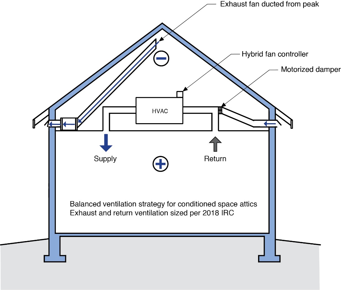
One of the best ways to remove moisture from the attic space is to provide air change. With the air change approach, air is exhausted from the peak of the attic using an exhaust fan ducted to the exterior. This creates a slight negative pressure in the attic and air is drawn in from the house below. To create “balanced” ventilation in the house, supply air is provided from the outside to the return side of the air handler (Figure 2). The quantity of this air flow should be based on the International Residential Code (IRC) 2018. To prevent over-ventilation or under-ventilation, a motorized damper is installed at the outdoor air supply of the system. The operation of the motorized damper is coupled or linked to the operation of the attic exhaust fan – the attic exhaust fan operates only when the motorized damper is open and the HVAC system blower is operating.
Another approach is to provide balanced ventilation with heat recovery (an HRV) or energy recovery (an ERV). When heat recovery or energy recovery is used, exhaust air is pulled from the peak of the attic (as shown in Figure 2) and supply air is provided from the occupied portion of the house.
A third approach is to provide dehumidification (a “dehumidifier”) to the attic space.
A fourth approach is to provide ducted supply and ducted return air to the attic space using the HVAC system in the house. With this approach the attic or roof space is directly coupled to the occupied portion of the house and the moisture control strategy for the house is used to provide moisture control for the attic space. Note that this fourth approach can only be used with spray foams that are not combustible or are covered or protected from fire.
Because this approach results in a sealed attic, any combustion appliances installed in the attic should be direct-vent sealed-combustion appliances that vent outdoors.
Despite the advantages of using spray foam under the roof deck, there are some potential risks. The primary risks are rainwater leaks, condensation from diffusion and air leakage, and built-in construction moisture. Hygrothermal modeling sponsored by the DOE Building America program and conducted by Building Science Corporation confirmed that even when the roof was modeled with rainfall leaks of up to 1% through the roof sheathing or with initial moisture content of the wood framing and sheathing of up to 18%, roofs insulated with open- or closed-cell spray foam could dry out sufficiently on a seasonal basis. Damage could occur if wood moisture content was above 18%, or if repeated or prolonged leaks above 1% were experienced and if the wood was unable to dry out. However, proper construction techniques, including the following measures, will minimize or eliminate the potential for moisture-related roof damage. (See Grin, Smegal, and Lstiburek 2013 for more details.)
How to Install Spray Foam on the Underside of the Roof Decking
- Make sure the installation complies with the 2018 International Residential Code (2018 IRC; see the Compliance tab for more details). The requirements of the 2018 IRC Section R806.5 “Unvented attic and unvented enclosed rafter assemblies” are summarized here: Unvented attic assemblies and unvented enclosed rafter assemblies are permitted if all the following conditions are met:
- The unvented attic space is completely within the building thermal envelope.
- Interior Class I vapor retarders (e.g., plastic sheeting) are not installed on the ceiling side (attic floor) of the unvented attic assembly (i.e., under the ceiling) or on the ceiling side of the unvented enclosed rafter assembly.
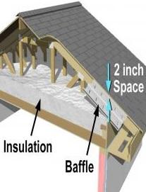
- Where wood shingles or shakes are used, a minimum ¼ inch (6.4 mm) vented airspace separates the shingles or shakes and the roof underlayment above the structural sheathing.
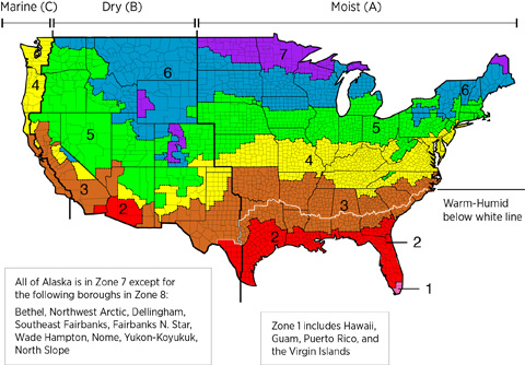
- In Climate Zones 5, 6, 7, and 8, any air-impermeable insulation shall be a Class II vapor retarder, or shall have a Class II vapor retarder coating or covering in direct contact with the underside of the insulation.
- The attic or rafter assembly meets one of the following conditions regarding the air permeability of the insulation directly under the structural roof sheathing.
- Where only air-impermeable insulation is provided, it shall be applied in direct contact with the underside of the structural roof sheathing.
- Where air-permeable insulation is installed directly below the structural sheathing, rigid board or sheet insulation shall be installed directly above the structural roof sheathing in accordance with the R-values in Table R806.5 for condensation control.
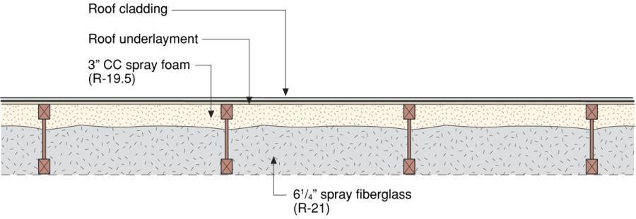
- Where both air-impermeable and air-permeable insulation are provided, the air-impermeable insulation shall be applied in direct contact with the underside of the structural roof sheathing in accordance with Item (a) and shall be in accordance with the R-values in Table R806.5 for condensation control. The air-permeable insulation shall be installed directly under the air-impermeable insulation.
- Alternatively, sufficient rigid board or sheet insulation shall be installed directly above the structural roof sheathing to maintain the monthly average temperatures of the underside of the roof sheathing above 45°F (7°C). For calculation purposes, an interior temperature of 68°F (20°C) is assumed and the exterior air temperature is assumed to be the monthly average outside temperature of the three coldest months.
- Where preformed insulation board is used as the air-impermeable insulation layer, it shall be sealed at the perimeter of each individual sheet interior surface to form a continuous layer.
- Ensure, when using open-cell spray foam, that a low-perm Class II vapor retarder is installed where required – typically Climate Zones 5, 6, 7 and 8.
- Provide appropriate fire resistance and flammability requirements for the spray foam selected and installed (“thermal barrier” or “ignition barrier”). Note that not all spray polyurethane foams require thermal or ignition barriers.
- Refer to the current state and local building codes for the minimum R-value of air-impermeable insulation required for the roof assemblies in your climate. Also refer to the current state and local building codes – particularly in Climate Zones 5, 6, 7 and 8 – regarding the requirements for Class II vapor retarder coatings or layers.
- Inspect the roof assembly to ensure it has proper drainage protection above the roof deck.
- Measure the moisture content of the wood prior to applying spray foam insulation to ensure it has dried to below 19% or to the levels recommended by the spray foam manufacturer.
- Ensure the weather conditions and temperatures for installing the insulation are as recommended by the spray foam manufacturer.
- Clean the surfaces of the roof sheathing and structural members so they are clear of any debris or dust to ensure proper adhesion of the spray foam.
- Cover any mechanical and electrical equipment and wiring prior to applying the insulation.
- Provide proper ventilation in the work area during application.
- Install the spray foam. It is recommended to hire a licensed professional applicator for the spray foam installation.
- Visually inspect the insulation installation to ensure that foam consistently meets the specified depth with no gaps or voids.
- Refer to the current state and local building codes for definition and requirements for the ignition and thermal barrier as well as vapor diffusion retarder requirements.
- Install additional cavity insulation as needed to meet the desired R-value. See Figure 3.
- Inspect and air seal all penetrations through the attic floor.
- Provide controlled ventilation, balanced ventilation with heat recovery, install a dehumidifier, or supply conditioned house air to the attic as described above.
- Ensure the home has good ventilation and that any combustion appliances installed in the attic are direct-vent sealed combustion appliances that vent outside.
How to Install Ducts in an Unvented Attic
When installing HVAC equipment in an insulated conditioned attic, good HVAC design principles still apply:
- Design a compact, duct layout with short, straight ducts runs. Seal and test ductwork for air leakage.
- Install a balanced ventilation system such as a heat recovery ventilator or central fan-integrated ventilation with a fresh air intake and integrated exhaust. (For more information, see Whole House Ventilation Strategies for Existing Homes.)
- Do not install low-efficiency combustion heating systems that draw their combustion air from the attic. Instead install direct-vent sealed-combustion furnaces or heat pumps. (For more information, see Combustion Furnaces, Traditional Split Heat Pumps.)
Ensuring Success
Provide for a very high degree of airtightness, preferably with a continuous membrane adhered to the top surface of the structural roof deck, with a layer of rigid insulation over it to provide condensation control. The spray foam itself can provide the airtightness when it is installed under the roof decking between framing elements; however, all wood-to-wood joints in the framing must still be sealed.
Keep the roof dry before spray foam is installed. Apply insulation to a debris- and dust-free surface to provide adequate thermal resistance to prevent condensation.
Spray polyurethane foam is a material that is essentially “manufactured” when applied at the building site. Given the importance of this material’s performance, quality control measures should be set in place. Some key issues include moisture content and temperature of the substrate, applied spray foam layer or “lift” thickness, ratios of the two spray foam components during application, and storage/handling of spray foam components. Further information is available at the Spray Polyurethane Foam Alliance.
Air seal the ceiling plane and seal around penetrations through the ceiling plane for ducts, flues, wiring, soffits, etc., to prevent warm moist air from the house from entering the attic space. See the Guide to Attic Air Sealing for more information on combustion safety, ventilation for indoor air quality, and attic ventilation for durability related to insulating an attic.
Ensure the following conditions are met to prevent risk of moisture damage to roofs when installing spray foam under the roof decking:
- the installation complies with the 2018 International Residential Code,
- the roof sheathing and framing are dry below 19% before spray foam is installed, and
- when using open-cell spray foam, a low-perm Class II vapor retarder is installed where required – typically Climate Zones 5, 6, 7 and 8.
These recommendations were based on hygrothermal modeling conducted by Building Science Corporation and sponsored by the DOE Building America program, which modeled the impacts of rainfall leaks or initial wood moisture content on open- or closed-cell spray foam-insulated roofs in several climate zones. Modeling showed that the roofs were able to dry out sufficiently to avoid durability issues if the initial moisture content was under 18% or where rainfall leaks of up to 1% were modeled. Damage could occur if wood moisture content was above 18% or if prolonged leaks above 1% were experienced and if the wood was unable to dry out. However, making sure that wood is dry before initial installation, proper construction techniques including installation of a water-proof roofing membrane, and ensuring that the roof can dry to the inside will minimize or eliminate the potential for moisture-related roof damage. (See Application of Spray Foam Insulation under Plywood and Oriented Strand Board Roof Sheathing for more details.)
When installing HVAC equipment in an insulated, conditioned attic, design a compact duct layout with short, straight ducts runs. Seal and test ductwork for air leakage. Install a balanced ventilation system. Install high-efficiency direct-vent, sealed-combustion furnaces or heat pumps.
Region
In high wind regions – particularly in coastal areas – wind-driven rain is a problem with vented attic and vented roof assemblies. Additionally, during high wind events, vented soffits have been known to collapse leading to building pressurization and window blowout and roof loss due to increased uplift. Unvented conditioned attics and roofs are safer during hurricanes; they –– outperform vented attics and roofs principally due to the robustness of their soffit construction.
In coastal areas, salt spray and corrosion are a major concern with steel frames, metal roof trusses, and truss plate connectors in vented attics and vented roofs. This is not an issue with unvented, conditioned attics and roofs.
In flood areas, provision should be provided to allow access to roof tops if refuge, rescue, and evacuation becomes necessary. This can be provided by installing operable skylights or dormers or other alternatives that allow egress.
In cold climates, interior relative humidity can directly affect the sheathing moisture content with open-cell or closed-cell spray-foamed roofs and Building Science Corporation recommends that winter-time relative humidity in homes located in Climate Zones 6, 7, or 8 should be maintained below 35% (Grin, Smegal, and Lstiburek 2013).
Open-cell spray foam should be a Class II vapor retarder or be coated with a Class II vapor retarder in cold climates 5, 6, 7, and 8 (2012 IRC R806.5. Note, the 2012 IRC says “or be coated with a Class III vapor retarder.” “Class III” is a typo which has been corrected to Class II in the 2015 I codes.) Class I vapor retarders should not be installed on the ceiling side of any spray foam installed on the underside of the roof decking in any climate zone as the vapor retarder will prevent drying to the inside in case of a roof leak.
The map in Figure 1 shows the climate zones for states that have adopted energy codes equivalent to the International Energy Conservation Code (IECC) 2009, 12, 15, and 18. The map in Figure 2 shows the climate zones for states that have adopted energy codes equivalent to the IECC 2021. Climate zone-specific requirements specified in the IECC are shown in the Compliance Tab of this guide.

Training
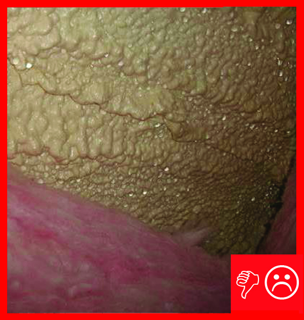
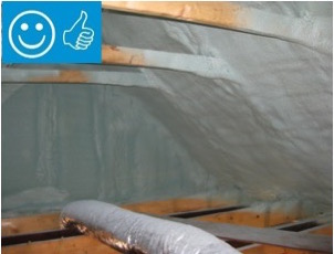
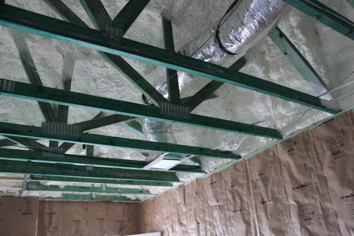
Right and Wrong Images
Source
Report covering moisture and leakage issues associated with spray foam insulation application to the underside of roof sheathing.
Source
Source
Source
Source
Source
Source
Videos
Compliance
Retrofit
For existing homes, see the new home guidance in this guide and see the Solution Center guide Below Deck Spray Foam Insulation for Existing Roofs.
More Info
Case Studies
References and Resources
Application of Spray Foam Insulation Under Plywood and Oriented Strand Board Roof Sheathing, BA-1312
*For non-dated media, such as websites, the date listed is the date accessed.
Contributors to this Guide
The following authors and organizations contributed to the content in this Guide.
Sales
High-R Attic Insulation = High-Efficiency or Ultra-Efficient Attic Insulation
Technical Description
There are two levels of attic insulation: high-efficiency insulation, which meets the 2015 International Energy Conservation Code, and ultra-efficient insulation, which is 25% more efficient than this national code. Using high-efficiency and ultra-efficient insulation along with professional installation (e.g., no gaps, voids, compression, or misalignment with air barriers; complete air barriers; and minimal thermal bridging) creates conditioned spaces that require very little heating and cooling, along with even comfort and quiet throughout the house.
Questions? Comments? Contact our webmaster.