

Scope
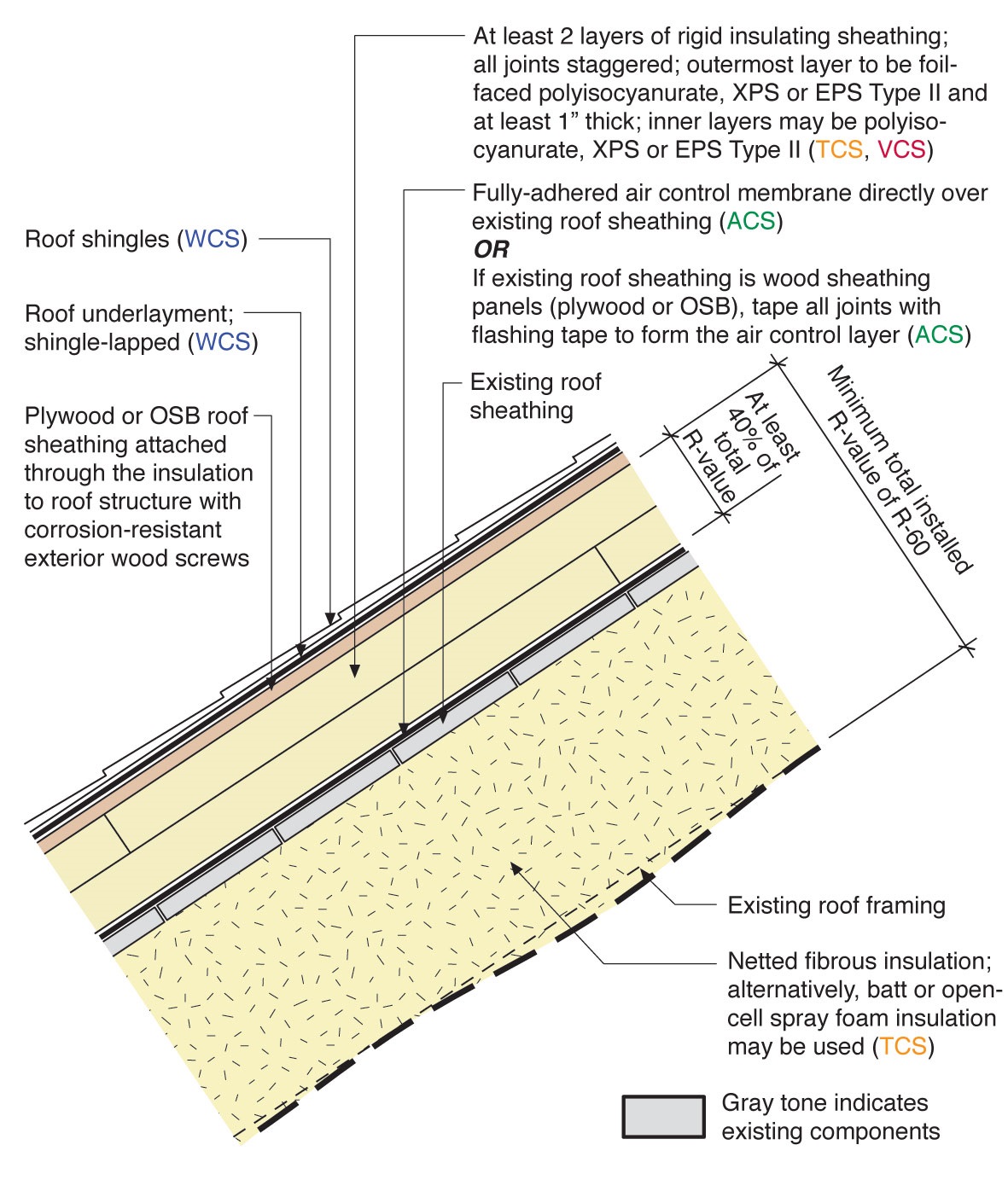
Install Insulating sheathing above the roof deck on existing homes. This retrofit assembly is appropriate for homes with conditioned attics or where the retrofit is intended to create a conditioned attic.
- Remove existing roofing and non-adhered underlayment to expose roof sheathing.
- Apply continuous air control membrane to existing roof sheathing or implement continuous air control at roof sheathing.
- Install rigid insulation board in multiple layers with joints offset vertically and horizontally between adjacent layers. Rigid insulation layers exterior to existing roof sheathing must provide sufficient thermal insulation (R-value) to control condensation risk (see climate specific guidance).
- Install nailbase for cladding. Nailbase must be vented in high snow-load areas.
- Install roofing underlayment, flashing, and cladding as per best practices. See Step and kick-out flashing at roof-wall intersections, extending ≥ 4” on wall surface above roof deck and integrated with drainage plane, and Self-sealing bituminous membrane or equivalent at all valleys & roof deck penetrations.
- Install cavity insulation (e.g. netted fibrous insulation, batt insulation) to achieve desired total assembly R-value. See Insulation Installation (RESNET Grade 1) - Part 1 and Insulation Installation (RESNET Grade 1) - Part 2.
See the Building America Solution Center guide on Pre-Retrofit Assessment of Attics, Ceilings, and Roofs for more information.
The U.S. Department of Energy’s Standard Work Specifications has additional information on above roof deck insulation.
See the Compliance Tab for links to related codes and standards and voluntary federal energy-efficiency program requirements.
Description
This guide provides information about installing Insulating sheathing above the roof deck on existing homes with a ventilating air gap between the above-deck insulation and the roof covering. This retrofit assembly is appropriate for homes with conditioned attics or where the retrofit is intended to create a conditioned attic.
Air Control Membrane
The existing roof cladding as well as non-adhered underlayment must be removed in order to allow an air control membrane to be installed or established at the roof deck. Robust air control is essential for a high performance enclosure. An air control membrane is needed below the insulating sheathing to prevent moisture-laden air from migrating through the joints in the insulating sheathing. With the right materials and detailing, the air control membrane can also provide temporary water protection and permanent back-up water protection.
There are three options for an air control membrane installed on top of the roof sheathing these are listed relative to air control and temporary/back-up water control performance:
Good – Non-adhered roof underlayment made air tight with taped seams and air tight connections to the air control of adjacent assemblies. Make sure all seams are properly lapped.
Better – Self-adhered air and water control membrane. Because of the insulation exterior, the product may not need to be specifically designated for roof applications, however, traction on steep slopes must be a priority consideration as it relates to workers’ safety. Make sure all seams are properly lapped.
Best – Fully-adhered, self-sealing ice and water control membrane, installed shingle style.
If the existing roof sheathing is made up of wood sheathing panels (plywood or OSB) the air control membrane can also be established at the roof sheathing by taping the joints between sheathing panels.
Above-Deck Insulation
The insulation installed over the roof deck must be installed in multiple layers with joints offset in order to control convective looping at joints between insulation panels.
Materials appropriate for insulating sheathing with unvented cladding substrate include:
- Polyisocyanurate,
- Extruded polystyrene (XPS),
- Expanded polystyrene (EPS) type II, and
- Semi-rigid mineral fiber insulation boards PROVIDED the material has adequate compressive strength. Mineral fiber with compressive strength of 0.625 psi at 10% deformation has been shown to work in wall systems where 1x4 furring strips are installed over the insulation.
In a configuration with a vented cladding substrate (such as used for ice dam protection in high snow load areas), the outer layer of insulating sheathing must be detailed as a drainage plane. Therefore, it must have surfaces that provide a suitable substrate for flashing or sheathing tapes. More information on using insulating sheathing as a drainage plane is available in the Taped Insulating Sheathing Drainage Planes Guide. Insulation materials appropriate for the outer layer of insulating sheathing include:
- XPS or
- Foil-faced polyisocyanurate.
Roof Cladding Substrate
An unvented roof cladding substrate (e.g. plywood or OSB roof sheathing) can be installed over exterior insulation layers using long exterior-grade screws. The screws must be long enough to penetrate an adequate depth into the roof framing. Marking the location of framing on successive layers is very important in locating the framing particularly when the framing has irregular spacing.
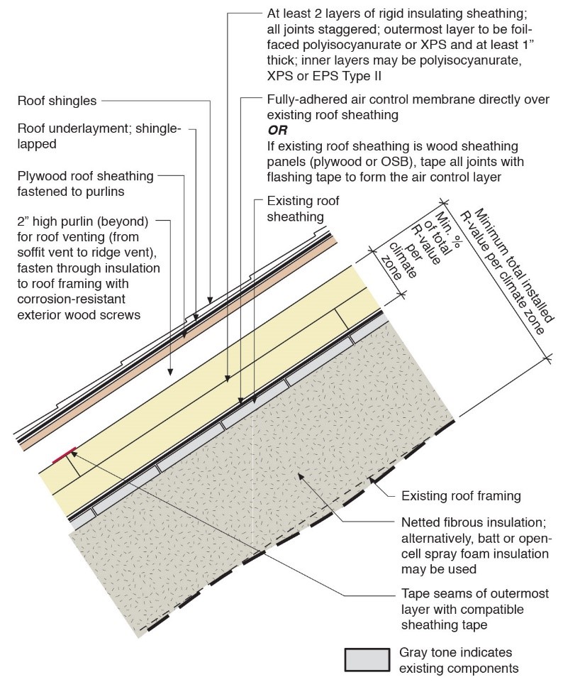
If purlins are used to create a vented over-roof, the purlins are fastened to the framing through the insulating sheathing. The substrate for the roof cladding is then fastened to the purlins much as it would be fastened to a new roof. Gaps along the length of the purlins can provide cross ventilation such as would be necessary to effectively vent a roof with hips, valleys or other obstructions to the soffit-to-ridge ventilation space. Large gaps in the purlins must be coordinated with the nailing pattern for the cladding substrate.
Once the substrate for the roof cladding is installed, installation of roofing underlayment, flashing, and cladding follows best practices. See Step and Kick-Out Flashing at Roof-Wall Intersections, extending ≥ 4” on wall surface above roof deck and integrated with drainage plane, and Self-sealing bituminous membrane or equivalent at all valleys & roof deck penetrations.
Cavity Insulation
Installation of cavity insulation follows typical best practices. See Insulation Installation (RESNET Grade 1) - Part 1 and Insulation Installation (RESNET Grade 1) - Part 2. Note that too much insulation installed to the interior can upset the condensation control of the assembly.
If installing closed-cell spray foam or other low permeance insulation to the interior, it is very important to verify that the roof sheathing and framing are dry (e.g. 12-15% moisture content or less) before installing cavity insulation. It is also a good idea to verify that sheathing and wood framing are dry before installing any kind of cavity insulation.
It is generally best to install cavity insulation only after the new exterior water management system is installed. However, in certain circumstances, it may be desirable and necessary to install cavity insulation from the exterior. The risk that must be managed is water penetration to the roof sheathing or cavity insulation after installation of cavity insulation. Although a properly designed assembly will be able to control the condensation risk of diffusion or air transported moisture, the insulation to the interior of the roof sheathing will inhibit the ability of the assembly to dry if a bulk water leak occurs. The system is more vulnerable to leaks between the time that the existing roofing is removed and new water control systems are installed. If water leaks into the assembly after insulation is installed, the insulation must be removed, the source of the leak identified and corrected, and the sheathing and framing allowed to dry thoroughly (e.g. 12-15% moisture content) before cavity insulation is replaced.
Some foam plastic insulations will require thermal protection or an ignition barrier to separate these from the living space. Consult the manufacturer of the insulation material and the local building code to learn of specific requirements.
How to Retrofit a Roof to a High Performance Roof with Insulating Sheathing above the Roof Deck Plus Cavity Insulation in Roof Framing
- Remove existing roofing and non-adhered roof underlayment.
- Apply a continuous air control membrane to existing roof sheathing -OR-Tape all joints between roof sheathing panels with an acrylic or butyl adhesive flashing tape/membrane.
- Mark the location of framing on the air control membrane to facilitate attachment of roofing substrate or purlins.
- Seal around any penetrations through the air control layer. If the air control layer is to provide water control, provide proper flashing as well as air sealing for penetrations.
Install rigid insulation board over the air control layer in multiple layers with joints offset vertically and horizontally between adjacent layers.
If Providing a Vented Over-Roof
- Detail the outer layer of the insulating sheathing as a drainage plane (see Figure 1).
- Transfer the markings for framing locations through each layer of insulating sheathing.
- Tape seams in rigid foam.
- Install vertical purlins (furring strips).
- Install decking or horizontal furring strips to attach roof covering (OSB or plywood decking required for asphalt shingles).
- Install underlayment and flashing details. See Step and kick-out flashing at roof-wall intersections, and Self-sealing bituminous membrane or equivalent at all valleys & roof deck penetrations.
- Install roof covering.
Source
Ensuring Success
Exterior insulation permits high R-value to be achieved without necessarily disturbing interior finishes. The best time to implement this approach from a cost perspective is when an existing roof is being replaced.
Important health and safety prerequisites for high-performance enclosure retrofits
This high-performance retrofit measure is likely to have a significant impact on the dynamics of air, vapor and heat flow within the home. Certain measures must be implemented to ensure that these changing dynamics do not have negative ramifications for health and safety. It is also necessary to ensure that parts of the building not directly affected by the work are able to support and protect the planned work.
Prior to implementing a high-performance roof retrofit assembly it is important to do the following:
- Ensure combustion safety for combustion equipment located within the pressure boundary.
- Remediate any hazardous conditions that will be affected (e.g. exposed or aggravated) by the planned work.
- Ensure that the roof system provides robust protection from rain water and ice dams and that proper flashing is in place. Note that the retrofit measure featured in this guide includes installation of new roofing. Implementation of effective roof water management is taken to be part of this measure. Also ensure that the roof structure is adequate to support any additional load that may be added.
- Provide mechanical ventilation if not already provided.
Combustion safety
Provide minimum combustion safety by providing direct-vent sealed-combustion equipment or forced draft equipment (see Direct Vent Equipment). When furnaces, boilers, and water heaters are installed within the home’s pressure boundary, ideally this equipment would be direct-vent sealed-combustion equipment. If existing equipment is not direct-vent sealed-combustion or forced draft, the homeowners must decide whether to:
- replace equipment with direct vent or forced draft equipment, or
- retrofit forced-draft to existing equipment.
Providing make up air through passive inlets is not compatible with high-performance objectives.
Hazardous materials
Hazardous materials that will be affected by the retrofit work or that may impact the indoor air quality must be remediated and/or removed. Examples of hazardous materials that may be found in attic/roof assemblies of existing structures include (but are not limited to) lead, asbestos, animal dropping/remains, etc. Items stored in an attic space may also present potential hazards. Follow applicable laws and industry procedures for mitigation of hazardous materials. Engage the services of a qualified professional when needed.
Guidance for mitigating asbestos-related issues from HUD, EPA, NIH, OSHA and FEMA is available in Homeowner's and Renter's Guide to Asbestos Cleanup After Disasters and Asbestos: Worker and Employer Guide to Hazards and Recommended Controls.
Roof condition
A structural evaluation may be needed to determine if the roof is capable of supporting expected snow loads above a high R-value attic/roof assembly. Engage the services of a qualified professional when needed.
Ventilation
Provide whole-house and local exhaust (source control) mechanical ventilation complying with Section M1507 of the 2012 International Residential Code. Providing mechanical ventilation may be implemented concurrent with or as part of the larger attic/roof retrofit project.
Performance imperatives for high R-value roof retrofit using insulating sheathing above the roof deck plus cavity insulation in roof framing
The following measures are necessary to ensure high levels of performance for this roof retrofit strategy.
Rain water control
Effective water control is essential to the performance of any attic/roof system. Because this strategy involves exterior insulation and “over-roofing” it presents the opportunity to establish a robust water control system at the roof. The water control for a sloped roof includes a rain shedding cladding (e.g. asphalt shingles), a water control layer such as roofing underlayment that is impervious to liquid water, and flashing that is integrated with the water control layer. See Step and kick-out flashing at roof-wall intersections, extending ≥ 4” on wall surface above roof deck and integrated with drainage plane, and Self-sealing bituminous membrane or equivalent at all valleys & roof deck penetrations.
It may be obvious but is worth noting that temporary rain water control will be needed during construction. The air control membrane installed over the existing sheathing may be able to provide temporary rain water control if it is a water impermeable material and is appropriately detailed.
Air control
Effective air control is essential to the thermal performance of this measure as well as to condensation control. In this retrofit assembly the air control membrane is installed directly above the existing roof deck and below insulating sheathing. The air control membrane must be connected in a continuous manner to the air control membrane of adjacent assemblies.
Condensation control
If vapor permeable or air permeable insulation is used in the roof framing below the roof deck, then the insulation above the roof deck must be sufficient to control condensation risk at the roof sheathing. Table R806.5 in the 2012 IRC (R806.4 in the 2009 IRC) indicates the amount of insulation above the roof deck required for condensation control assuming minimum required total insulation. High R-value unvented roof assemblies will require a proportionally larger amount of insulation above the roof deck for condensation control. Generally, 40% of the total assembly R-value should be above the roof deck. More insulation is needed above the roof deck in colder climates and where indoor relative humidity is above ~35% in winter. See BSD-163: Controlling Cold Weather Condensation Using Insulation.
In roof assemblies with deep roof framing cavities that make it difficult to limit the amount of insulation below the roof deck, large amounts of insulation may be required above the roof deck in order to control condensation.
Dry sheathing
Protect the structure during construction. Especially in climates where rain is a common occurrence, it is a good idea to detail the air control layer installed over the existing roof sheathing as a temporary water control layer.
Insulation installed to the interior of the roof deck will reduce the ability of the roof deck to dry to the interior. The exterior water management must be fully implemented and verified before roof cavity insulation is installed. Any roof sheathing or framing that was exposed to water during construction must be allowed to dry thoroughly before installation of insulation (e.g. to a moisture content of 12%). Use a moisture meter to verify wood moisture content below 12% prior to installing closed-cell insulation or other vapor impermeable or semi-vapor impermeable insulation to the interior side of the roof deck.
Thermal protection
Unless the manufacturer has obtained appropriate approvals for the product, foam plastic insulations used inside the attic will require a thermal protection or ignition barrier covering. Gypsum wall board can provide appropriate thermal protection. Intumescent paints may be compatible with some foam plastic products. Typically the combination of specific intumescent paint and foam plastic insulation product will have to have been tested and approved.
Connection to adjacent assemblies
The thermal control of a high R-value roof retrofit can be bypassed if the assembly is not properly connected to thermal control at the walls. If a gabled attic is to be brought into the thermal enclosure, the gable walls will need to be insulated as well. The connection between the roof assembly and wall assembly is critical for air control.
Making the Contractor’s Life Easier
Mark the location of framing on successive layers so that workers can more easily hit framing with fasteners when needed. It is especially important to keep track of framing locations in retrofit because the framing may have irregular spacing.
Region
Insulation requirements by region
The minimum insulation requirements for ceilings, walls, floors, and foundations in new homes, as listed in the 2009, 2012, 2015, and 2018 IECC and IRC, can be found in this table. Additional code requirements are listed on the Compliance tab of this guide.
Insulation for condensation control
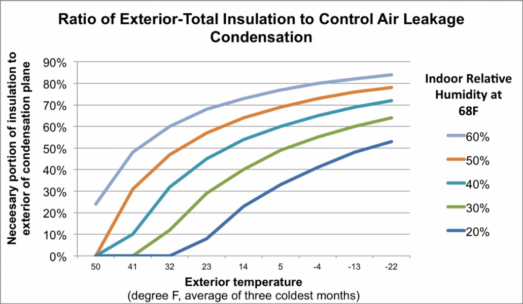
Insulation above the roof deck or air/vapor impermeable insulation below the roof deck is needed for condensation control in an unvented roof. The ratio of insulation above the roof deck or air permeable insulation below the roof deck is a matter of climate and interior conditions. Generally, more insulation is needed for condensation control in colder climates. Also, the higher the indoor humidity, the more insulation is needed to avoid condensation.
The chart below illustrates the amount of insulation relative to total insulation that is needed to control condensation. This chart is adapted from “Controlling Cold-Weather Condensation Using Insulation” (Straube 2011). The insulation controlling condensation can be entirely above the roof deck, or it can be air and vapor impermeable insulation below the roof deck, or it can be a combination of insulation above the roof deck and air/vapor impermeable insulation below the roof deck.
Source
Article describing research encouraging use of exterior insulation to warm interior sheathing surfaces in walls and roof assemblies to reduce the likelihood of condensation during cold weather
Ventilated over-roof
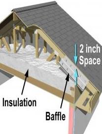
In regions with greater than 50 pounds per sf ground snow load the roof cladding substrate must be vented to prevent ice damming. The substrate or nailbase is attached to purlins installed over the top of the exterior insulation to create a ventilation cavity. The ventilation cavity must be 2” clear between the cladding substrate and exterior insulation (Lstiburek 2006). The cavity between purlins is vented by a ventilation opening at the bottom (eave) and at the top (ridge) – if the ventilation cavity cannot be connected directly to both a soffit and ridge vent, then the purlins must be made discontinuous to allow crossflow.
With the ventilated over-roof approach, the top of the exterior insulation should be detailed as a drainage plane to allow incident water to be drained from the system.
Training
Videos

More Info
References and Resources
*For non-dated media, such as websites, the date listed is the date accessed.
Contributors to this Guide
The following authors and organizations contributed to the content in this Guide.
Building Science Corporation, lead for the Building Science Consortium (BSC), a DOE Building America Research Team
Sales
High-R Attic Insulation = High-Efficiency or Ultra-Efficient Attic Insulation
Technical Description
There are two levels of attic insulation: high-efficiency insulation, which meets the 2015 International Energy Conservation Code, and ultra-efficient insulation, which is 25% more efficient than this national code. Using high-efficiency and ultra-efficient insulation along with professional installation (e.g., no gaps, voids, compression, or misalignment with air barriers; complete air barriers; and minimal thermal bridging) creates conditioned spaces that require very little heating and cooling, along with even comfort and quiet throughout the house.
Questions? Comments? Contact our webmaster.