

Scope
In cold climates (2012 IECC Climate Zones 5 and higher), install a protective membrane along the roof eaves to help protect the edge of the roof from ice dam formation.
- Use a self-sealing bituminous membrane with a peel-and-stick adhesive backing or a similar product.
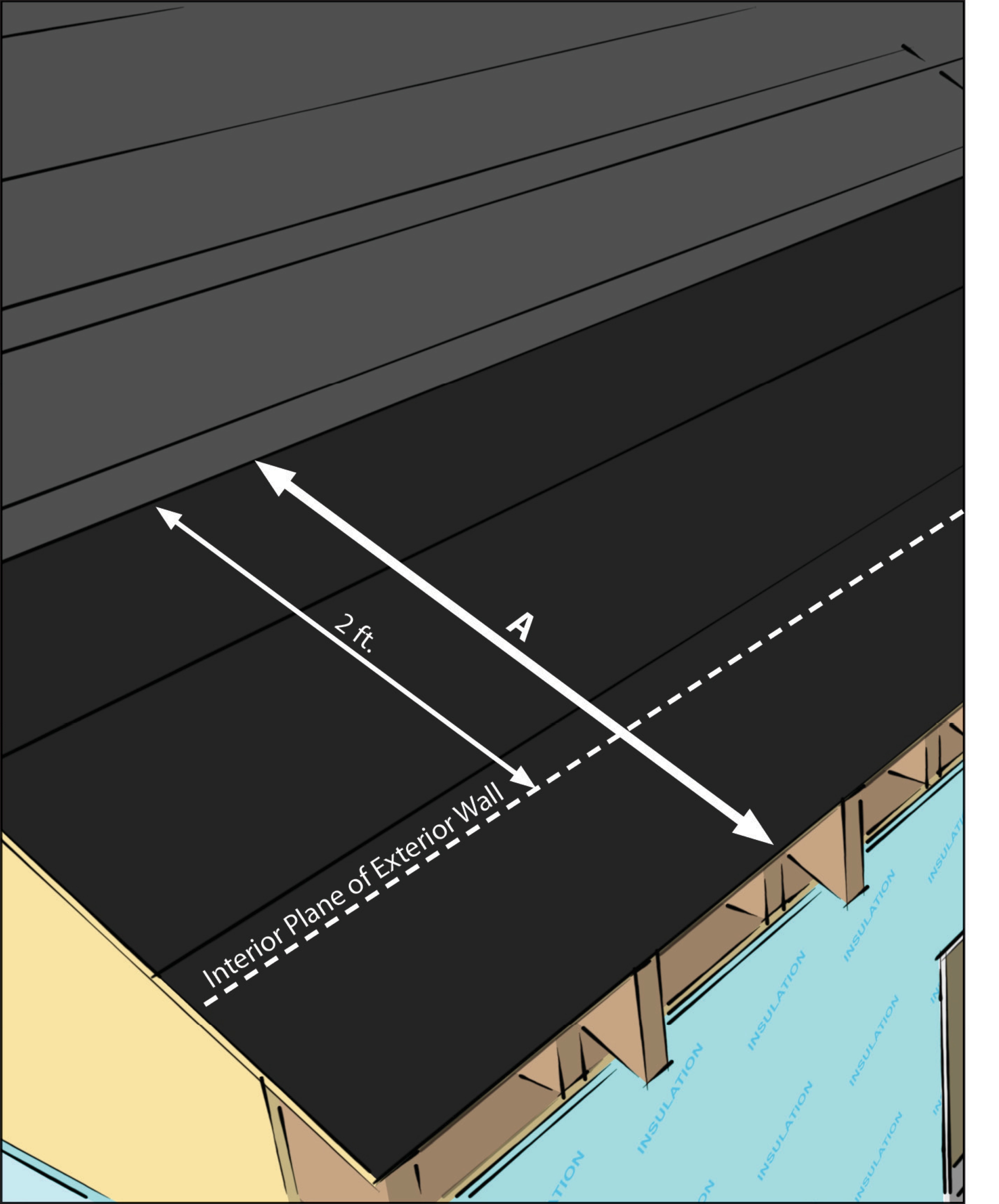
- Install the membrane from the eaves to at least two feet in from the interior plane of the wall.
- The lower edge of the membrane should cover the top edge of the metal drip edge.
- On roofs with a slope that is equal to or greater than 8 units vertical in 12 units horizontal, install 3 or more feet of ice and water shield from the eave edge up along the slope edge (IRC 2015).
This membrane is not required by ENERGY STAR in cold-dry climates or in warm climates (IECC 1-4).
See the Compliance Tab for links to related codes and standards and voluntary federal energy-efficiency program requirements.
Description
Cold climates present a special challenge to a home's roof. During the cold months when snow and freezing rain fall, a thawing-freezing process can occur that could lead to the formation of ice dams. Ice dams can occur during certain conditions, such as when snow accumulates on the roof, then melts although the air temperature is at or below freezing. This melting can occur because of poor insulation or air leaks in the ceiling which allow heat from the home to escape into the attic and warm the underside of the roof. Warmth from sunlight on exposed dark roof surfaces can also contribute to this snow melt. The melted snow flows down to the roof eaves and refreezes in the cold air. Some of this water will drip off the edge and freeze in the form of icicles, but water can also freeze above the edge of the roof and form ledges or dams that continually build up and begin to block the liquid water flowing down from above. Once the process starts, ice can rapidly dam up to the point where several gallons of water are being held back. In severe cases, ice dams have caused roof collapses. In less severe cases but sometimes just as damaging, the accumulating water can back up between the shingles then saturate and penetrate the roof underlayment and begin leaking into the attic. (See the Training tab for a video about ice dam formation.)
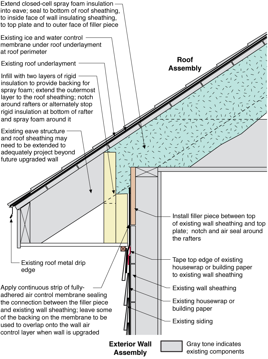
Prevention is the best cure. Good air sealing of the ceiling plane and/or roof deck, adequate attic insulation, and ventilation of the attic (or roof assembly if over an unvented attic) can reduce or mitigate the heat transfer to the roof deck and subsequent snow melt and ice dam formation. It is especially important to maintain adequate insulation over the exterior wall top plates (for example by designing roof trusses with raised heels, and/or insulating this area with polyiso rigid foam or spray foam) and to maintain air flow from soffit vents (through the use of insulation baffles).
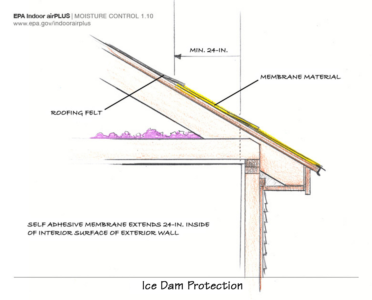
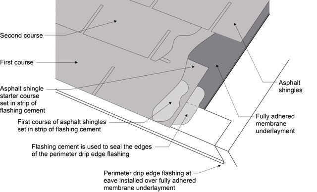
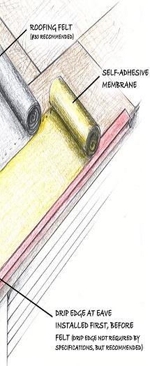
To protect the roof from ice dam damage, install a self-adhered, self-sealing bituminous membrane over the roof deck along the eaves (see Figure 1). The membrane should extend up from the eaves to two feet above the inside edge of the exterior wall plane. Bituminous membrane is a heavy, flexible material that has been impregnated with a petroleum-based solution like tar to make it waterproof. Most products are sold in long rolls; many come with a "peel-and-stick" adhesive backing. Bituminous membrane is self-sealing in the sense that it will remain somewhat soft and will seal around nails driven through it, for example to hold shingles.
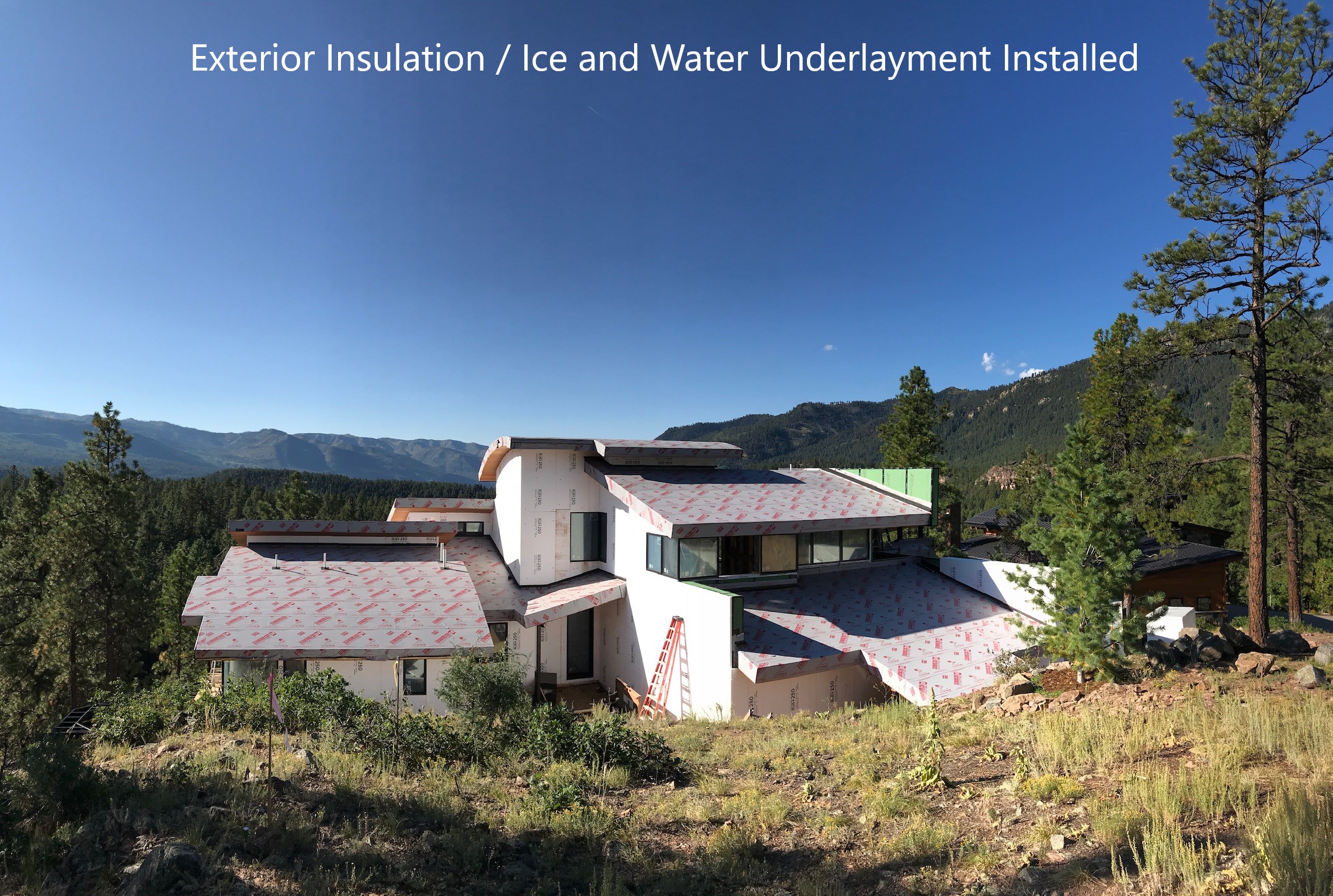
Although most ice dams are likely to occur within 2 feet up the roofing deck from the interior plane of the exterior wall, some builders will choose to go further up the roof deck, especially in locations where there may be high snow loads or extended periods of snow cover. Some builders choose to cover the entire roof deck with self-adhering self-sealing membrane especially in high-snow or high-wind areas. Builders in warm-climate hurricane-prone areas may also choose to cover their roofs with self-adhering membrane for storm protection.
How to Install Self-Sealing Bituminous Membranes along Eaves
- Clean the roof deck (typically plywood) from the edge of the eaves to at least two feet up the roofing deck from the interior plane of the exterior wall where the material will be applied. Make sure the area is free of loose nails and wires, debris, dust, oil, or water to ensure the membrane will adhere properly.
- Install eave drip edge.
- Measure the length of the eave to be covered.
- Cut the self-sealing bituminous membrane to length. For extremely long eaves, cut the material in shorter, more manageable lengths and apply, starting at the lower point and working up, overlapping the membrane sections by 6 inches in shingle-like fashion. Some peel-and-stick membranes come with a split backing above the adhesive, allowing you to peel and fasten first one half than the other. If using this type of product, align and adhere the lower half first.
- Secure the material in place with a heavy roller The material must lay flat with no gaps, creases, or folds.
- Install the underlayment directly over the membrane. Install rake drip edge (See Figure 2). Continue with roof construction.

How to Install Self-Sealing Bituminous Membranes along Eaves for Ice Dam Protection
In cold climates (IECC climate zones 5 and higher), the self-sealing bituminous membrane must be installed at least 2 feet beyond the interior plane of the exterior wall. In simple terms, this means that the membrane must be installed all the way from the edge of the roof deck over the eave and up the roof over the attic space at least 2 feet. To successfully do this, use the following overall installation guidance:
- Determine how far up the roof deck from the eave edge the self-sealing bituminous membrane should be installed. To do this, measure from the exterior wall inward 2 feet and add the estimated wall depth including interior and exterior sheathing, framing, drywall, and siding. Next simply mark the roof deck directly above your measurement and ensure the membrane is installed to at least that point on the roof deck.
- Calculate, based on membrane roll width, how many courses of membrane need to be installed.
- Install the membrane starting at the eave edge and working up the roof deck. Courses should overlap per manufacturer's recommendation.
Installation note: Make sure the self-sealing bituminous membrane extends over the metal drip edge. This will ensure that water will not find access at the very edge of the eave.
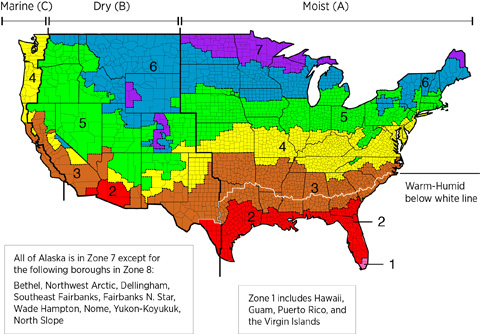
Exception: Self-adhesive bituminous membranes do not need to be applied in dry climates as defined in IECC Figure 301.1. Refer to the IECC climate zone map shown on the Climate tab to determine "Dry Climates," and consult code officials when local climate conditions might dictate the need for protection from ice dams.
Ensuring Success
To ensure that the area above the eave is well sealed, the area must be cleaned prior to installation of the self-adhering bituminous membrane. Once applied, the membrane must be rolled flat so that no folds or creases are present.
Region
The map in Figure 1 shows the climate zones for states that have adopted energy codes equivalent to the International Energy Conservation Code (IECC) 2009, 12, 15, and 18. The map in Figure 2 shows the climate zones for states that have adopted energy codes equivalent to the IECC 2021. Climate zone-specific requirements specified in the IECC are shown in the Compliance Tab of this guide.

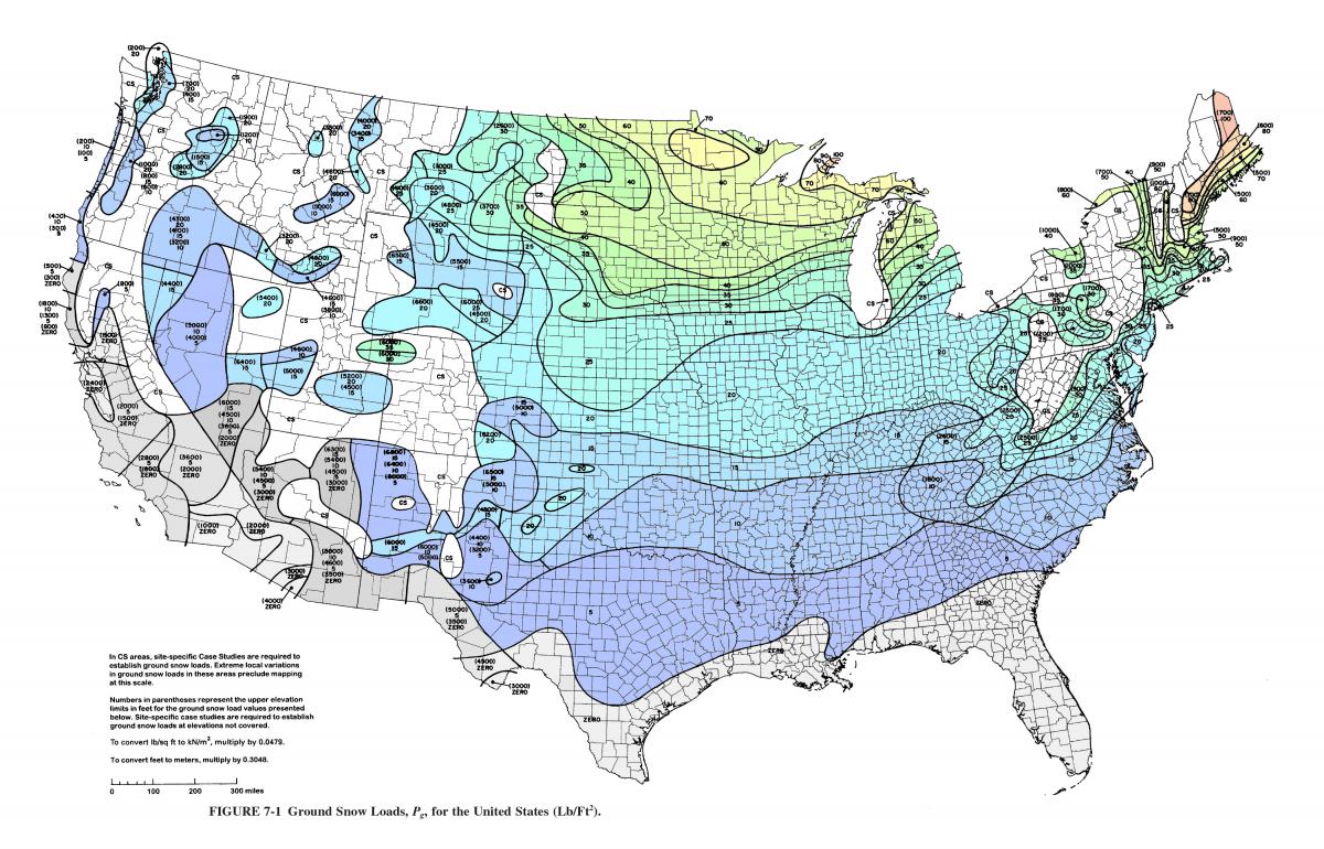
High Snow Load Areas
In high snow load regions (Figure 3), consider installing peel-and-stick membrane further up the roof than code-required minimums (e.g., 2 feet). Consider installing membrane on all roof deck surfaces expected to experience heavy or sustained snow load. Additional attention should be paid to attic air sealing, insulation, and venting in high snow load areas to reduce the risk of ice dam formation.
Training
Right and Wrong Images
Source
Source
Source
Guidebook providing useful examples of high performance retrofit techniques for the building enclosure of wood frame residential construction in a cold and somewhat wet climate.
Source
Guide describing details that serve as a visual reference for each of the line items in the Water Management System Builder Checklist.
Source
Videos

Compliance
More Info
References and Resources
*For non-dated media, such as websites, the date listed is the date accessed.
Contributors to this Guide
The following authors and organizations contributed to the content in this Guide.
Sales
Heavy Membrane Valley/Eave = Roof Water Barrier
Technical Description
Valleys and penetrations through the roof decking are some of the areas of the roof most vulnerable to leaks. A peel-and-stick bituminous membrane is installed for protection at these critical locations, including all roof valleys, roof-to-wall transitions, and roof edges to minimize ice dam damage in cold climates. Metal or plastic flashing is usually installed along with the membrane at wall intersections. Flashing is also installed around chimneys, vent stacks, and any other roof penetrations. Some builders install peel-and-stick membrane or a paint-on damp-proofing over the whole roof.
Questions? Comments? Contact our webmaster.