

Scope

Install step and kick-out flashing at all roof-wall intersections to protect walls from water intrusion, and install boot or collar flashing at all roof penetrations to protect roofs from leaks.
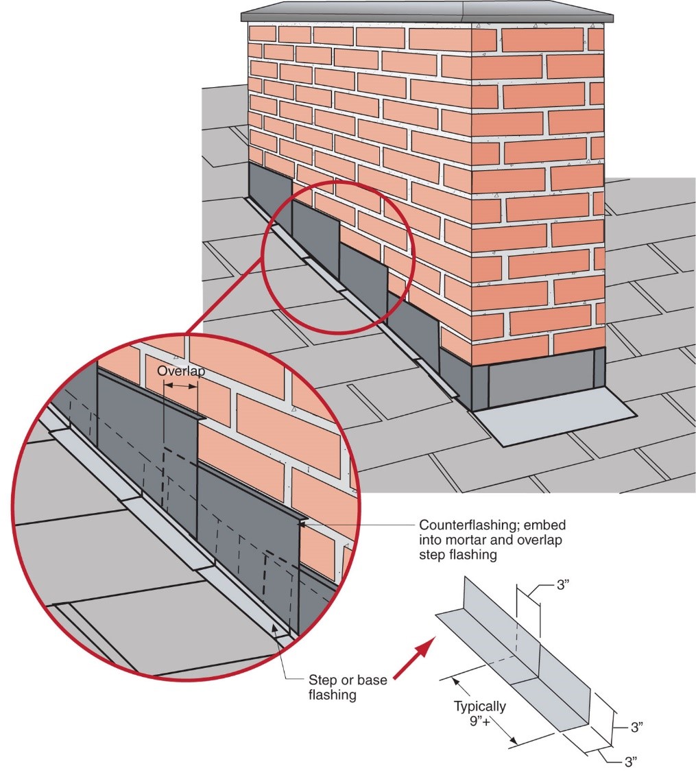
- Install corrosion-resistant flashing pieces that are overlapped in a shingle fashion.
- Extend step flashing at least 4 inches up the wall from the roof deck and at least four inches out along the roof deck (IRC 2015) and integrate the flashing with the drainage plane above (for example, overlap house wrap over it).
- If metal, the flashing should be made of galvanized steel at least 0.019 inches thick (IRC 2015).
- Install roof felt prior to installing the step and kick-out flashing.
- Install house siding over the step flashing, ending at least one inch above the roof surface.
- Install shingles over the portion of step flashing on the roof.
- When installing metal or rubber membrane roofs, use continuous flashing rather than pieces of step flashing.
- Install kick-out flashing at the end of a roof-wall intersection to divert water away from the wall and into gutters. Ensure that the kick-out flashing is large enough to handle expected stormwater flows.
- Install boot or collar flashings around all roof penetrations and properly integrate them with roof membranes and shingles above and below the penetration.
See the Compliance Tab for links to related codes and standards and voluntary federal energy-efficiency program requirements.
Description
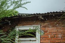
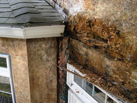
Heavy rains can pour thousands of gallons of water onto a home’s roof in a single storm. In multi-level house designs where roofs intersect walls, this roof-wall intersection will channel much of this water to drain off the roof and usually into a gutter. If sidewall flashing is lacking or inadequate, water can leak into the wall and cause serious water damage. In big storm events, rainwater can often overflow the gutter and stream down the walls. Diverters are sometimes fashioned onsite in an attempt to direct this water into the gutters. If undersized, these diverters are not very helpful. If not properly integrated with the WRB (water-resistant barrier, e.g., house wrap) and cladding, they can do more harm than good by allowing water inside the wall cavities. The result can be significant damage to wall sheathing, framing, insulation, and mold inside the wall cavities. While older wood siding would show evidence of this water intrusion by peeling paint, new wall claddings like fiber cement, vinyl siding, and brick veneer can mask the evidence for years.
Flashing is required at roof-wall intersections (step flashing) to divert water away from where the eave of a sloped roof intersects a vertical sidewall (kick-out flashing). Where flashing is metal, the metal shall be corrosion resistant with a thickness of not less than 0.019 inches (26-gauge galvanized sheet) (2018 IRC R903.2.1). To be effective, all flashing must be integrated with the roof and wall drainage planes shingle-fashioned, where the top layer of the WRB or flashing laps over the bottom layer to prevent water from draining behind the bottom layer.
Kick-out flashing directs rainwater into rain gutters, where it can be carried away from the structure. Kick-out flashing also referred to as diverters, can be fabricated on-site using sheet metal, but these can be undersized and may have unsealed seams that allow leakage. Prefabricated kick-out flashings are available as seamless, molded plastic pieces or metal with welded seams.
These materials would be installed by roofers in coordination with house wrap and siding installers. This task should be included in the contract for the appropriate trade, depending on the workflow at the specific job site.
Step flashings and kick-out diverters are required in the 2009 and 2012 IRC (R703.8) and 2015 and 2018 IRC (R703.4; R903.2.1). See the Compliance tab.
How to Install Sidewall Flashing and Kick-Out Diverters — On Homes with Rigid Foam Insulation Sheathing
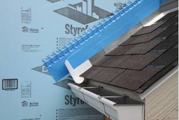
- Install the drip edge and roofing underlayment over the roof deck and lap the underlayment up the sidewall and over the rigid foam insulation a minimum of 8 inches (Figure 2).
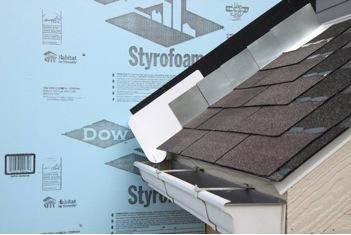
- Install the shingle starter strip at the roof eave in accordance with the roofing manufacturer’s instructions (Figure 3).
- Place the seamless, one-piece, non-corrosive kick-out diverter as the first piece of step flashing.
- Slide the kick-out diverter up the roof plane until the starter trough stops at the shingle starter strip. The diverter must be flat on the roof and flush with the sidewall (Figure 3).
- Fasten and seal the diverter to the roof deck and starter strip. (Do not fasten it to the sidewall.)
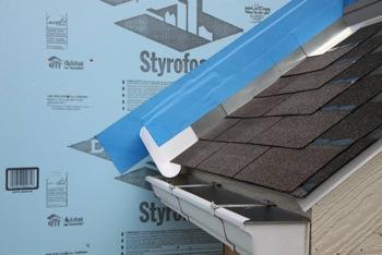
- Place the first row of shingles and the next section of sidewall flashing over the up-slope edge of the diverter, lapping a minimum of 4 inches over the diverter (Figure 4). Sidewall, and flashing height requirements, should be determined by a design professional and local building codes.)
- Install the remaining sidewall flashing, appropriate counter flashing, and shingles in accordance with the manufacturer’s instructions (Figure 5).
- Apply self-adhesive flashing over the top edge of the wall flashing, diverter, and rigid foam insulation (Figure 6).
- Apply construction tape over the self-adhered flashing (Figure 7).
- Apply siding over the rigid foam insulation.


How to Install Sidewall Flashing and Kick-Out Diverters — On Homes with House Wrap over OSB or Plywood Sheathing
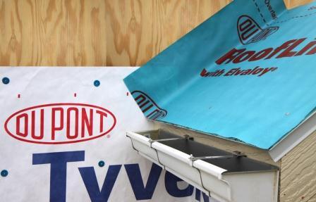
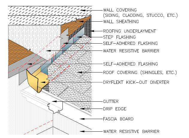
- Apply drip edge and roof underlayment over the roof deck (Figure 8). Continue lapping up the sidewall and over the weather-resistive barrier (in this case, house wrap) a minimum of 6 inches. A good construction practice is to leave a 1-inch gap between the vertical wall and fascia to accommodate the house wrap below the roof line. Install the shingle starter strip at the roof eave in accordance with the roofing manufacturer’s instructions (Figure 9).
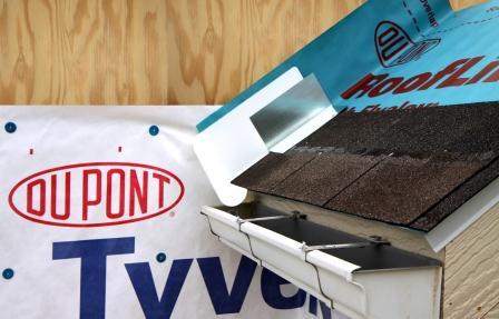
- Place the seamless one-piece non-corrosive kick-out diverter as the first piece of step flashing.
- Slide the kick-out diverter up the roof plane until the starter trough stops at the shingle starter strip. The diverter must be flat on the roof and flush to the sidewall.
- Fasten and seal the diverter to the roof deck and starter strip. (Do not fasten it to the sidewall.)
- Place the first shingle and next section of sidewall flashing over the up-slope edge of the diverter, lapping a minimum of 4 inches over the diverter, as shown in Figure 10. (The sidewall flashing height requirement should be determined by a design professional and local building codes.)
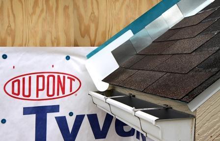
- Install the remaining sidewall flashing, appropriate counter flashing, and shingles in accordance with the manufacturer’s instructions (Figure 11).
- Apply self-adhesive flashing over the top edge of the wall flashing, diverter, and house wrap (Figure 12).
- Install the house wrap. Cut the house wrap to fit over the self-adhesive flashing and sidewall flashing (Figure 13). Note that these subsequent layers of house wrap, shown in Figure 13, will be installed shingle-fashion over the roofing underlayment, kick-out flashing, and base flashing. If house wrap and roofing are installed by different trades, it is important to coordinate this effort to maintain the drainage plane.
- Apply siding over the house wrap.
Ensuring Success
The site supervisor should visually inspect the step flashing and kick-out diverter during installation by trades to ensure that it is properly integrated with other wall and roof elements.
Region
Hurricane-Prone Regions
Roofing and wall cladding are more likely to be damaged or lost in hurricane-prone regions and other high-wind areas, leaving flashing and underlayment exposed and more susceptible to wind and water intrusion. Proper installation of flashing and sealing products is even more important in these areas to protect against storm damage.
The IRC does not have additional requirements for roof-wall flashing in hurricane-prone regions or other high-wind areas. Some local jurisdictions may have additional requirements or require specific product approval. Building codes establish minimum requirements, but products must also be installed in accordance with the manufacturer’s instructions. This is important because codes typically do not provide all of the detailed information for a durable installation. Assessments by FEMA after hurricanes commonly find that water intrusion and structural building failures are due to improper installation of building components. So, even where the IRC does not require additional measures, proper installation is more critical in hurricane-prone regions.
The Insurance Institute for Business and Home Safety® (IBHS) Fortified Home program offers guidance, best practices, and voluntary construction standards and programs for building in disaster-prone areas, including hurricane and other high-wind zones. The IBHS FORTIFIED Roof™ program includes options for sealed roof decks. IBHS also provides specific guidance for flashing roof-wall intersections.
Roof Drainage
The 2018 IRC requires roof water to be collected and discharged to the ground surface (i.e., rain gutters and downspouts) not less than 5 feet away from foundation walls or to an approved drainage system in areas where expansive soils or collapsible soils are known to exist (R801.3). Rain gutters are not necessarily required for other soil conditions but still may be necessary for proper site drainage requirements to direct water away from the foundation (R401.3).
The IRC does not have capacity, construction, or installation requirements specific to rain gutters. IBHS guidance in hurricane and high-wind areas addresses maintenance for gutters and downspouts but not sizing or attachment details. Local jurisdictions may have additional requirements or require specific product approval (e.g., see the Florida requirements below).
R903.4.2 One- and two-family dwellings and private garages. When gutters and leaders are placed on the outside of the buildings, the gutter and leaders shall be constructed of metal or approved plastic for outdoor exposure with lapped, soldered, or caulked joints and shall be securely fastened to the building with a corrosion-resistant fastening device of similar or compatible material to the gutters or downspouts.
Training
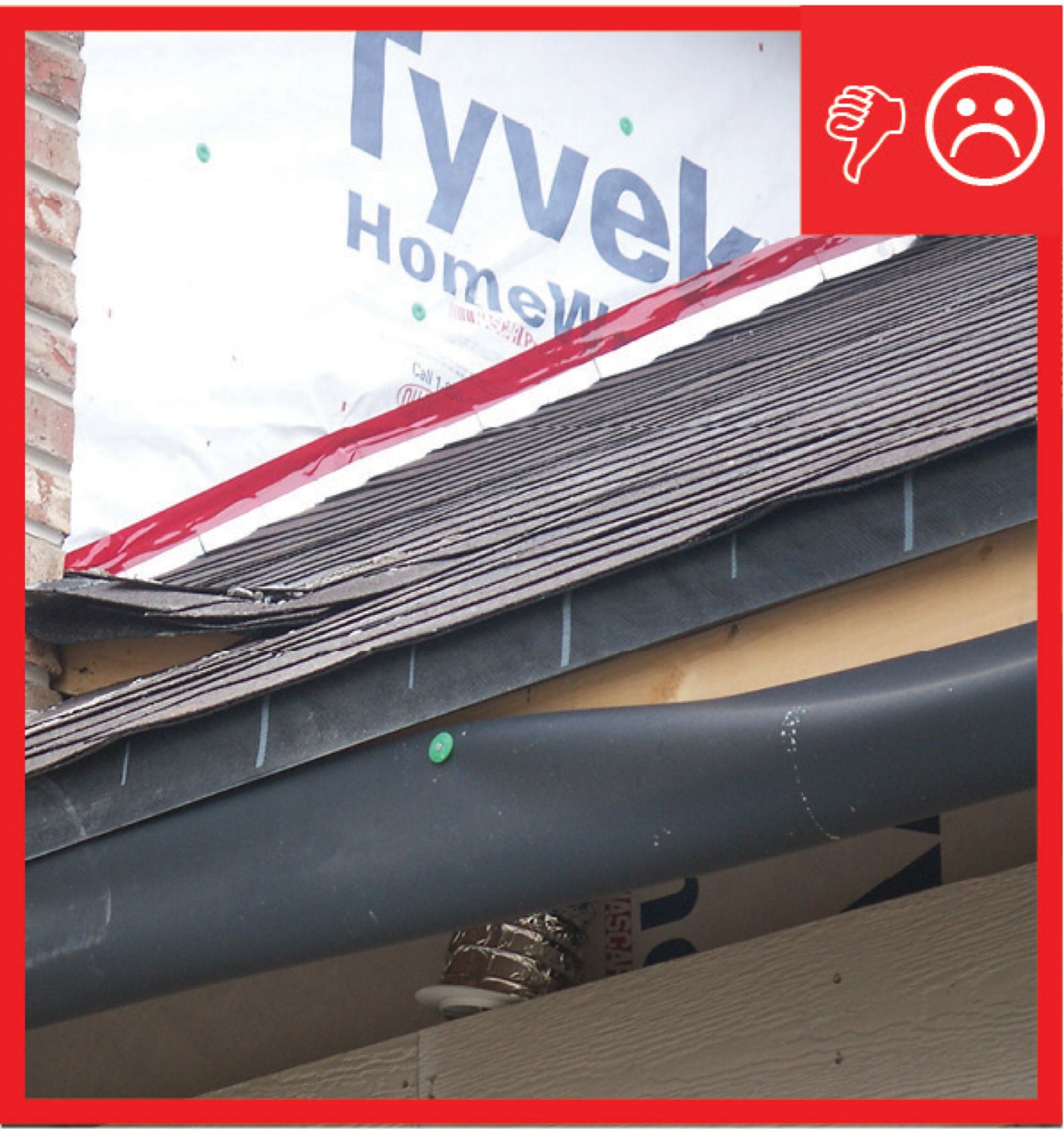
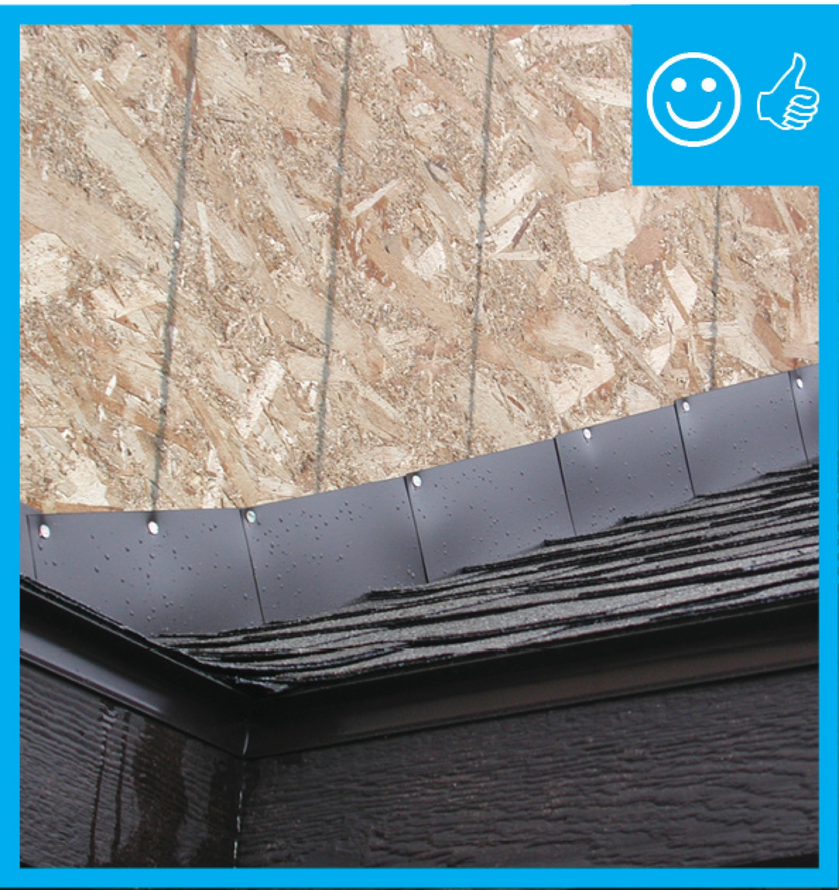
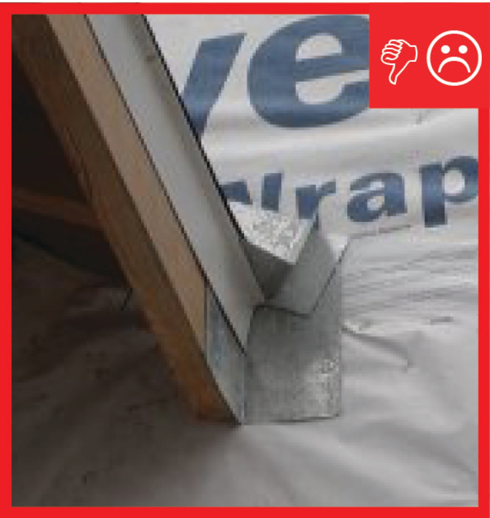
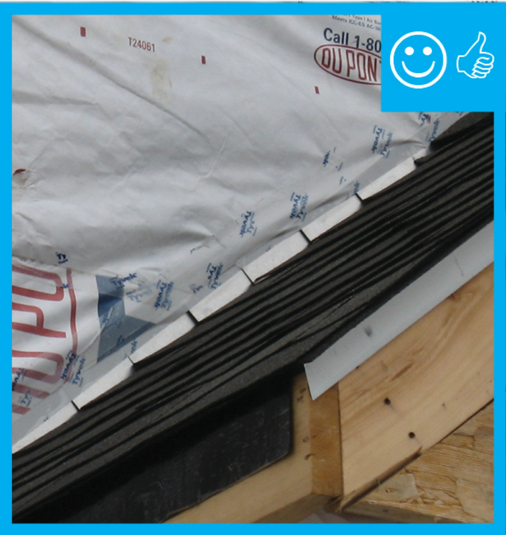
Right and Wrong Images
Source
Guide describing details that serve as a visual reference for each of the line items in the Water Management System Builder Checklist.
Source
Guide describing details that serve as a visual reference for each of the line items in the Water Management System Builder Checklist.
Source
Guide describing details that serve as a visual reference for each of the line items in the Water Management System Builder Checklist.
Source
Guide describing details that serve as a visual reference for each of the line items in the Water Management System Builder Checklist.
Source
Videos

Compliance
Retrofit
SCOPE
Before starting any retrofit project, consult the pre-retrofit assessment guides in the existing homes tool.
Install step and kick-out flashing at roof-wall intersections.
- Remove existing siding and shingles at the roof-wall intersection.
- Remove and repair any damaged siding and sheathing next to or beneath the roof-wall intersection.
- Install liquid waterproofing or peel and stick membrane on walls next to and beneath the end of the roof-wall intersection.
- Install kick-out and step flashing and lap correctly to direct water out from the wall; integrate it properly with the existing house wrap.
- Replace the siding over the step flashing.
DESCRIPTION
Missing kick-out and step flashing has been responsible for thousands of dollars worth of damage for homeowners. Signs of potential trouble include streaks of discoloration, mold, or algae along walls below wall-roof intersections, rotting wood, or peeling paint. However, with newer siding surfaces such as fiber cement and vinyl siding, there may be no visible exterior signs of damage even when water is pouring into the wall during every storm event and causing interior rot and mold inside the wall cavity.
The first step is to inspect the outside of the home and note all roof-wall intersections. Look for step flashing and kick-out flashing at those roof-wall intersections.
The step flashing should extend along the whole length of the roof-wall juncture. The individual pieces of metal flashing should be set so that each piece overlaps the piece beneath it; underlapped pieces can inject water into the wall rather than deflect water from the wall. The step flashing should be visible below the siding because siding installers should leave a .75- to 1.5-inch gap between the siding and the roof below. This gap can get covered over if the home has been roofed over since the siding was installed, thus building up the roof height. When re-roofing, it is best to remove and replace the step flashing to ensure it lays flat and is correctly aligned. If you are not reroofing, alternate the flashing with the existing shingles. Start from the bottom with kick-out flashing, as described in the Description tab. Along the wall, remove or cut away the siding a few inches up the wall. Fold back any intact existing house wrap and install peel-and-stick membrane on the wall and roof surface. Install metal flashing that has been bent to a right angle with five or more inches extending up the wall and 5 inches extending out along the roof. Install with one nail placed at the top corner of the flashing on the roof or the house wall, but not both, to allow for movement. Install a strip of house wrap along the step flashing that extends up under the house wrap above and down to an inch above the roof, as shown in the Description tab.
On older homes, if kick-out flashing exists at all, it is often fabricated on-site from pieces of flat metal flashing. Inspect existing kick-out flashing to determine if the size and angle are adequate for directing the water into the gutter and to see if there are any holes, even pinholes, in the kick-out flashing. Inspect the walls around the kick-out flashing for holes and for rot. If the kick-out flashing is missing or inadequate, remove and replace it. Prefabricated plastic and metal kick-out diverters are commercially available. Install as described in the Description tab. Some installers will recommend just cutting a vertical slit into the wall above the end of the gutter and lifting the bottom course of shingles, then sliding the kick-out flashing into that slot and under the shingle. This is a less-than-adequate fix as the flashing will not be properly integrated with the side flashing or house wrap, so the potential for future failure is higher, and the ability to see and repair current damage is limited.
The end of the gutter should not touch the intersecting wall; there should be a small gap to allow free drainage down the wall.
COMPLIANCE
See the Compliance tab.
More Info
Case Studies
References and Resources
*For non-dated media, such as websites, the date listed is the date accessed.
Contributors to this Guide
The following authors and organizations contributed to the content in this Guide.
Sales
Kick-Out Flashing, Step Flashing = Roof-Wall Water Deflector
Technical Description
Where roofs intersect walls is a critical point for flashing to prevent water leaks and damage. While wood siding may quickly show evidence of this water intrusion with peeling paint or staining, some wall claddings like fiber cement, vinyl siding, and brick veneer can mask the evidence for years. Roof step flashing must be effectively integrated with diverters known as kick-out flashing to effectively direct water to the gutters and avoid water damage.
Questions? Comments? Contact our webmaster.