
Below Deck Spray Foam Insulation for Existing Roofs

    Scope
    Scope Images
    Image
    Spray foam insulation was installed on the underside of the roof deck and on gable end attic walls to create an unvented attic
    Scope

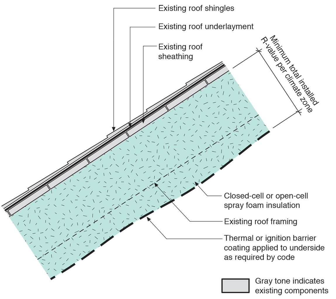
    Insulate an attic or roof in an existing home by installing spray polyurethane foam (SPF) insulation - either open cell or closed cell - on the underside of the roof deck as follows:

    • Inspect the existing roof shingles or roofing membrane for any deficiencies.  If there is any history or evidence of leakage, correct the leaks and repair the damage before proceeding.  
    • If the roof is at or near the end of its service life, consider replacing the roof to ensure the roof will provide acceptable water control.
    • Block the soffit vents.
    • Install spray polyurethane foam insulation (and additional insulation other than spray polyurethane foam if desired) in the roof cavity to levels that meet or exceed the current adopted building and energy codes.
    • Install a thermal barrier or ignition barrier (coating, gypsum board, or other material) over the spray polyurethane foam insulation if necessary based on the material properties of the spray polyurethane foam or as required by code.  Note that not all spray polyurethane foams require thermal or ignition barriers.
    • Seal any penetrations from the home into the attic through the attic floor.
    • Provide conditioning, dehumidification, or controlled ventilation to the attic.
    • Ensure the home has good ventilation.
    • If seeking to qualify an existing home to the criteria of the IBHS Fortified Home Hurricane and High Wind standards, the criteria to seal the roof deck can be met by applying closed-cell spray urethane-based foam adhesives along the joints between the roof sheathing and roof framing members as well as along all seams between the roof sheathing panels.

    See the following Building America Solution Center guides for more information:

    See the U.S. Department of Energy’s Standard Work Specifications (SWS) for more on installing spray polyurethane foam in unvented attics. 

    See the Compliance Tab for related codes and standards requirements, and criteria to meet national programs such as DOE’s Zero Energy Ready Home programENERGY STAR Single-Family New Homes, and Indoor airPLUS.

    Description
    Description

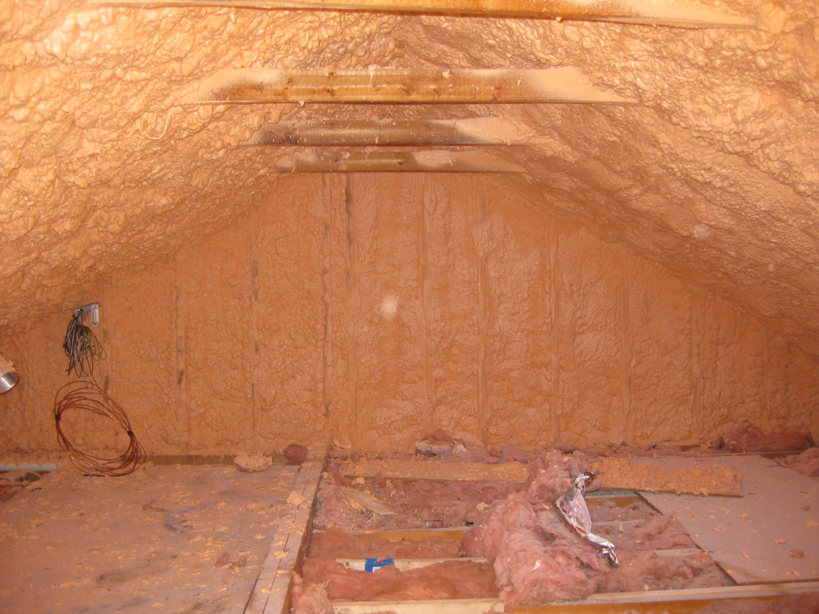
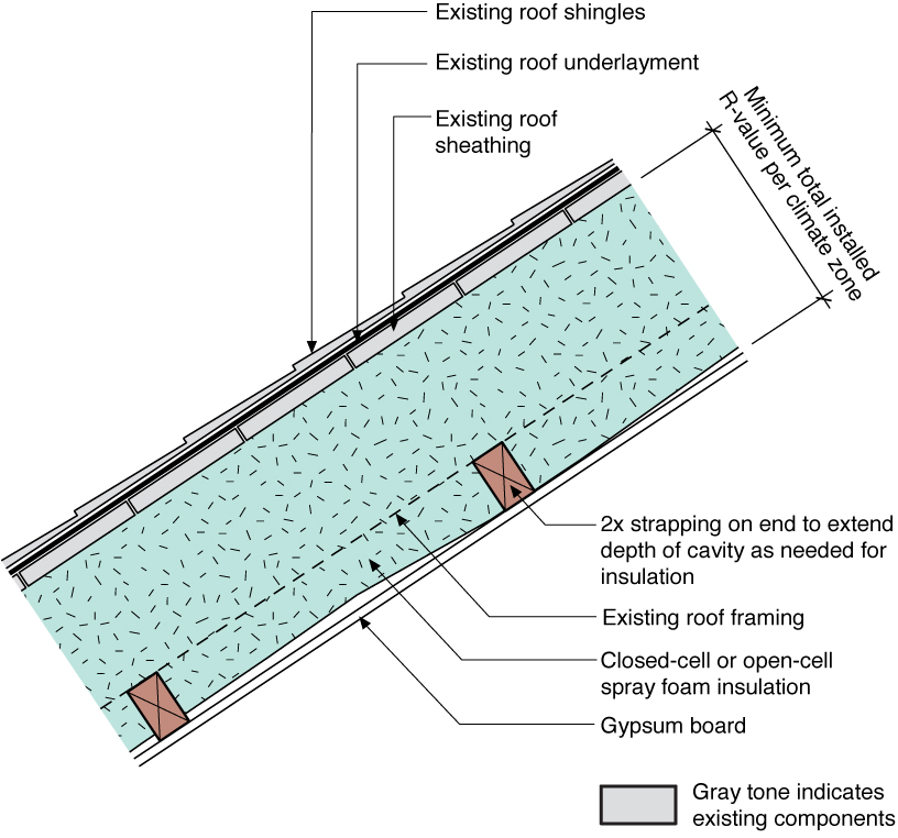
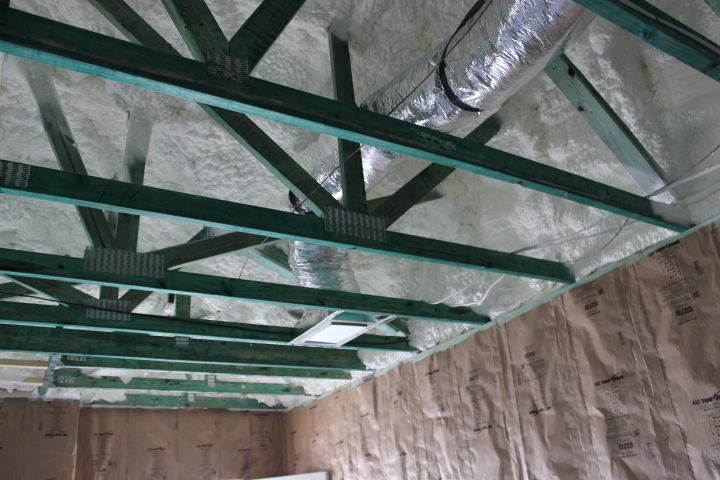
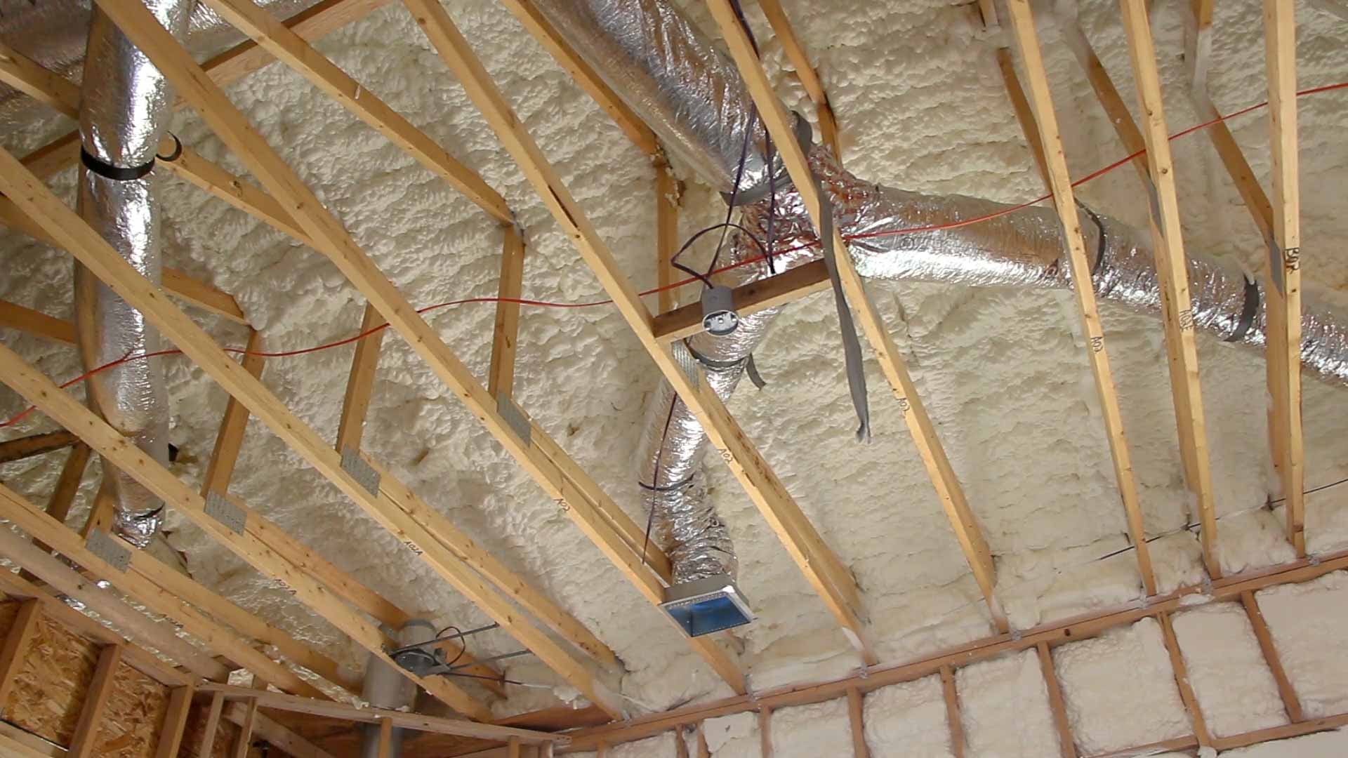
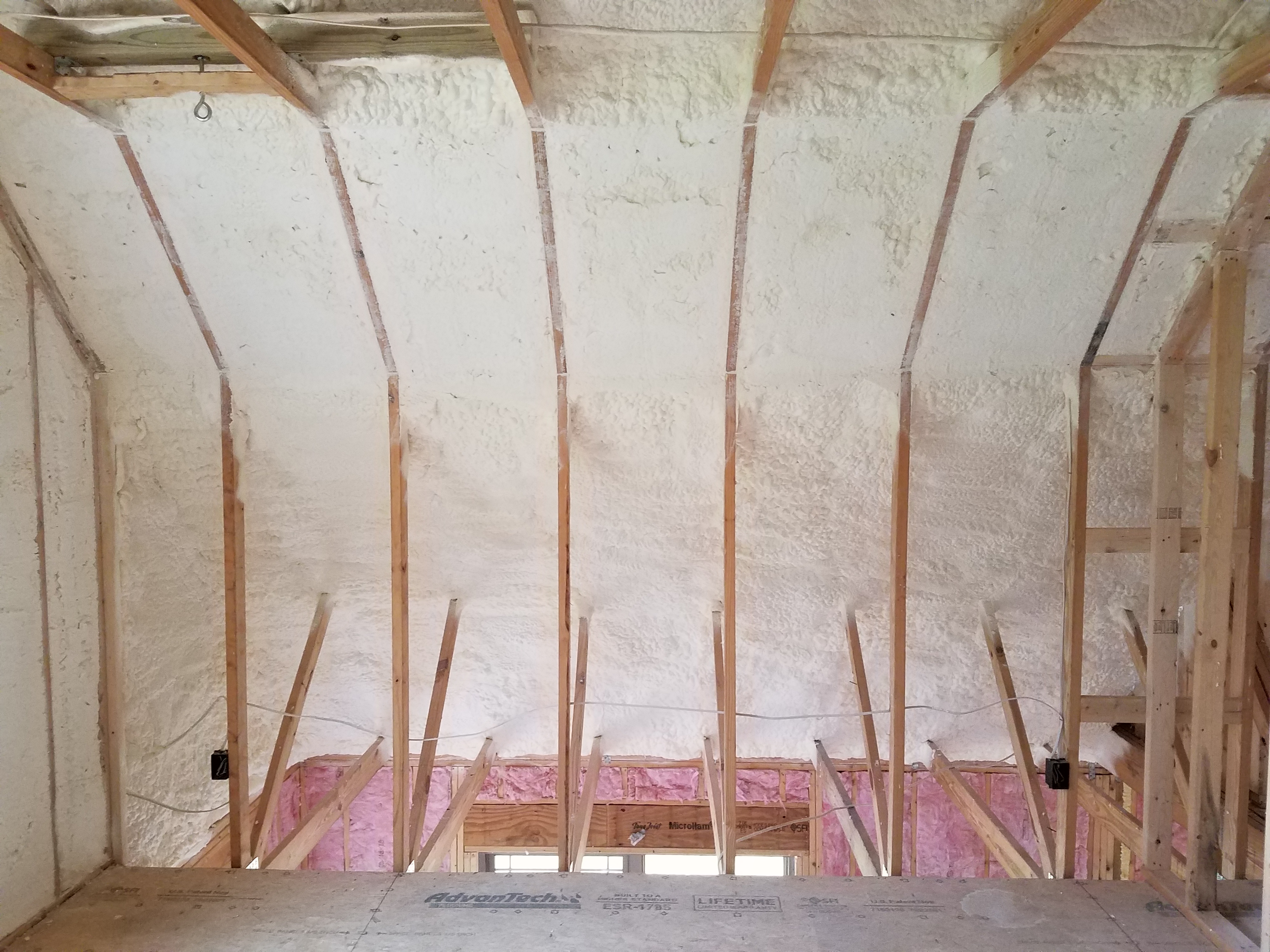
    This guide describes the conversion of a vented attic to an unvented insulated attic by installing spray polyurethane foam (SPF) insulation - either open cell (ocSPF) or closed cell (ccSPF) - on the underside of the roof deck (Figure 1). Note that all spray foams contain polyurethane – ocSPF, ccSPF bio-based spray foams, sugar-based spray foams, and water-blown spray foams.  

    Spray foam was installed on the underside of the roof deck of this existing home.
    Figure 1. Spray foam insulation was installed on the underside of the roof deck and on gable end attic walls to create an unvented attic (Source: Courtesy of Building Science Corporation).

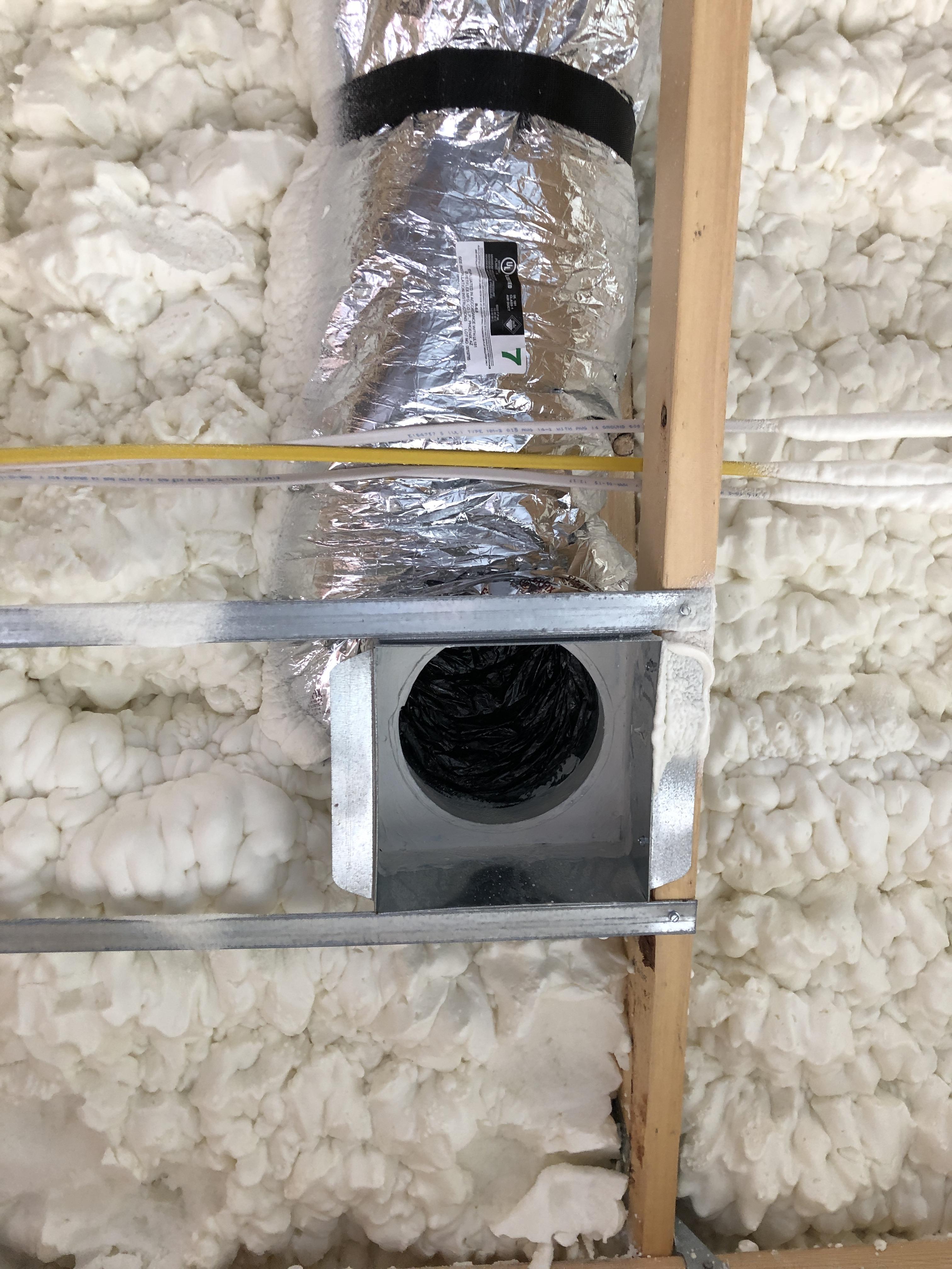
    Many older homes have little or no attic insulation. Attic insulation can be installed on the attic floor if the attic will be a vented attic. Or insulation can be installed along the underside of the roof deck, which converts the attic to an unvented conditioned attic that can provide a protected environment for HVAC equipment, conditioned storage space, and living area (habitable space) that can be resilient, durable, and efficient in all climate zones.

    Unvented conditioned attics and roofs are significantly more “fire safe” in wildfire areas and where neighboring buildings are close. Ash and embers enter vented attics through attic vents. No vents means no ash or embers entering attics and much less risk of fire. 

    In high wind regions – particularly in coastal areas – wind-driven rain is a problem with vented attic and vented roof assemblies. Additionally, during high wind events, vented soffits have been known to collapse leading to building pressurization and window blowout and roof loss due to increased uplift. Unvented conditioned attics and roofs are safer during hurricanes; they outperform vented attics and roofs principally due to the robustness of their soffit construction.

    If seeking to qualify an existing home to the criteria of the Insurance Institute for Building and Home Safety (IBHS) Fortified Home Hurricane and High Wind standards, the criteria to seal the roof deck can be met by applying closed-cell spray urethane-based foam adhesives along the joints between the roof sheathing and roof framing members as well as along all seams between the roof sheathing panels.

    In coastal areas, salt spray and corrosion are a major concern with steel frames, metal roof trusses, and truss plate connectors in vented attics and vented roofs. This is not an issue with unvented conditioned attics that have no vents where salt spray can enter. 

    In flood areas, provision should be provided to allow access to roof tops if refuge, rescue, and evacuation becomes necessary. This can be provided by installing operable skylights or dormers or other alternatives that allow egress.

    An unvented conditioned attic assembly should be considered if the attic will be used for habitable space, if the attic contains mechanical equipment or ductwork, if the roof structure is complex (i.e., difficult to vent due to obstructions), or if the ceiling plane is difficult to air seal (complex geometry or difficult access).  It is possible to create a vented assembly with insulation at the roof deck and spray polyurethane foam where the primary benefit of the spray polyurethane foam is its air sealing properties.

    If the roof has a low slope, there may not be sufficient space for the required insulation and ventilation space needed for a vented attic assembly, especially at the eaves, where insufficient insulation can contribute to ice damming. Therefore, low roofs are good candidates for conversion to an unvented conditioned attic with insulation along the underside of the roof deck.

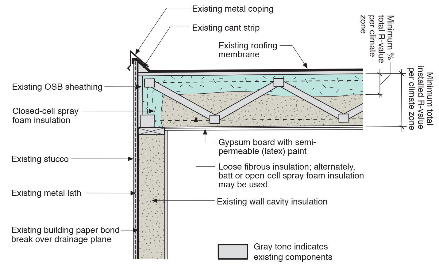
    This unvented conditioned attic or roof retrofit assembly approach applies all of the insulation to the interior side of the roof deck.  Most roof cladding and water control materials (asphalt shingles, asphalt papers, self-adhered roof membranes, etc.) are vapor impermeable.  In cold and mixed climates, this is effectively a vapor barrier on the “wrong side” of the assembly.  Therefore, to address interstitial (within-the-cavity) condensation risks, special attention should be paid to the type and the levels of insulation in the roof assembly.

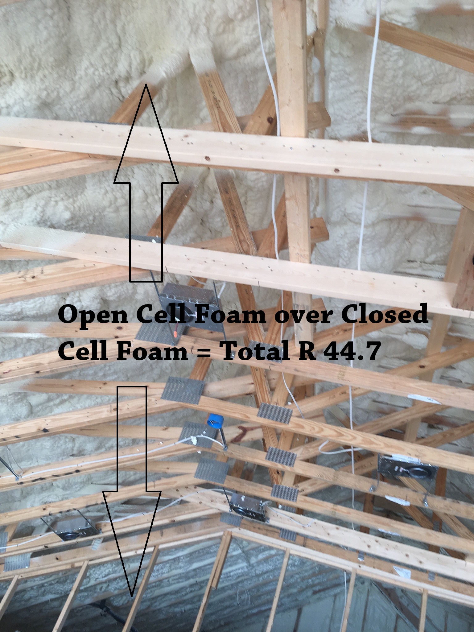
    The building codes (e.g., §R806.5 in 2018 IRC) specify a minimum R-value requirement for “air impermeable” insulation in a roof assembly, such as rigid insulation or spray foam, to control wintertime condensation.  In colder climate zones, the amount of air- and vapor-impermeable insulation required to control condensation increases.  If using a hybrid approach, it is important to meet or exceed the required ratio of air- and vapor- impermeable insulation to air- and vapor-permeable insulation within the roof assembly.

    For this assembly, replacement of the roofing is not required (unless it is at the end of its service life), but it is vital that the existing roof system provides robust protection from rainwater (“precipitation”), and that effective flashing and water control is in place.  The low permeance of the roof exterior (cladding and water control layer) combined with the reduced drying due to the application of spray polyurethane foam means that the sheathing is more vulnerable to damage from rainwater penetration.

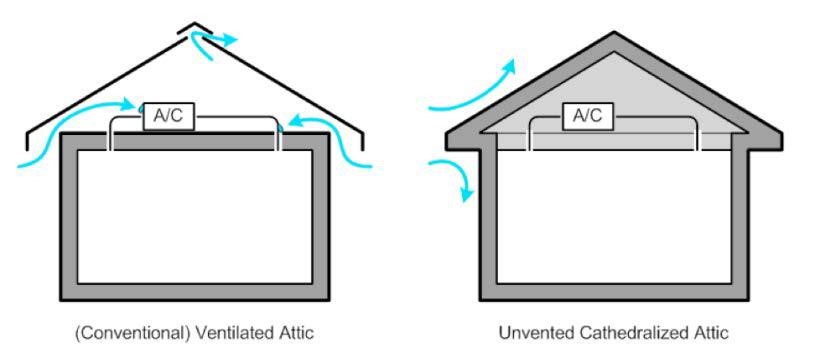
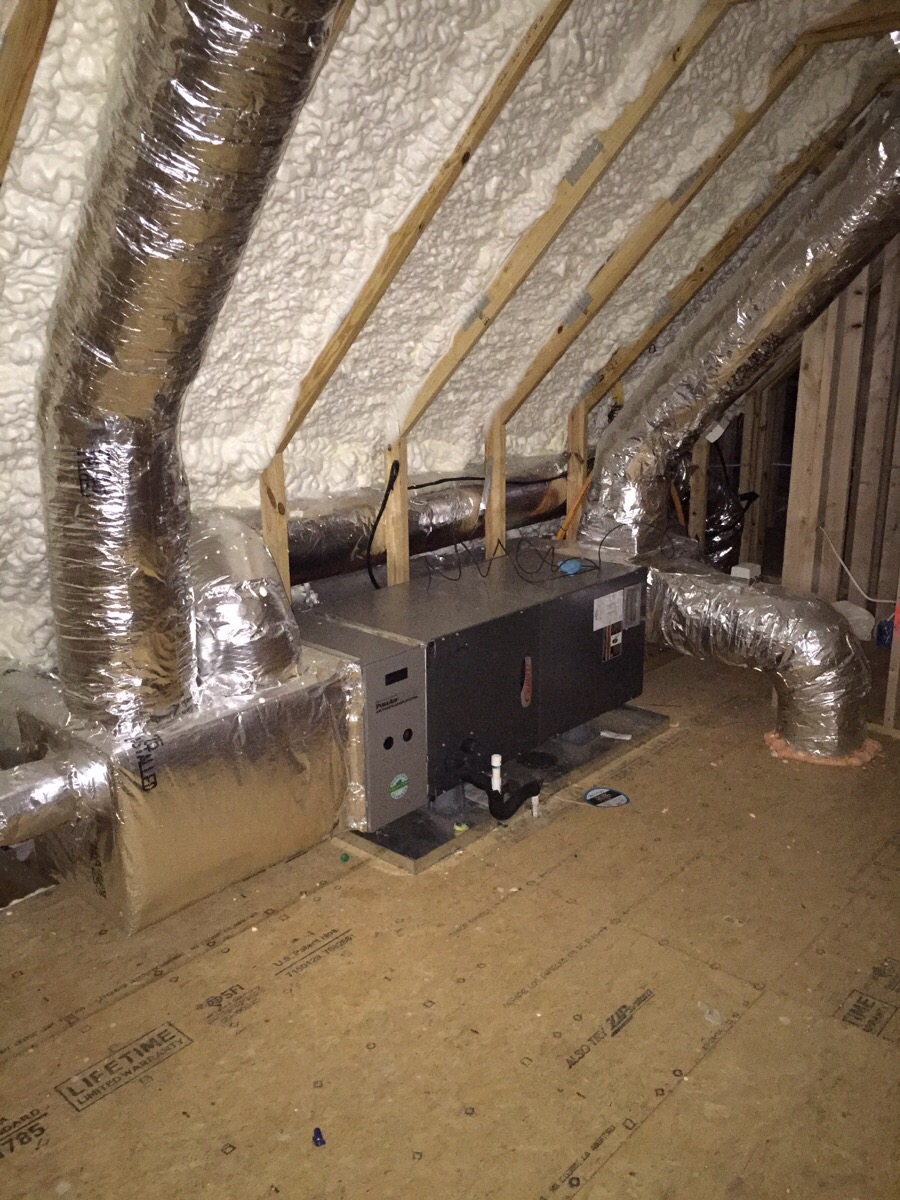
    Figure 2 shows how converting a conventional ventilated attic to an unvented cathedralized attic brings the HVAC equipment into “conditioned” space.

    Vented Attic vs Unvented Cathedral Attic Air Flow
    Figure 2. Constructing an attic that is unvented and is insulated along the roof line provides a conditioned space for HVAC equipment that is located within the home’s thermal envelope (Source: Courtesy of Building Science Corporation).


    Wherever vented unconditioned attics are converted to unvented conditioned attics, a means of moisture removal from the attic is necessary. The “conditioned” part of unvented conditioned attics or roofs is important. 

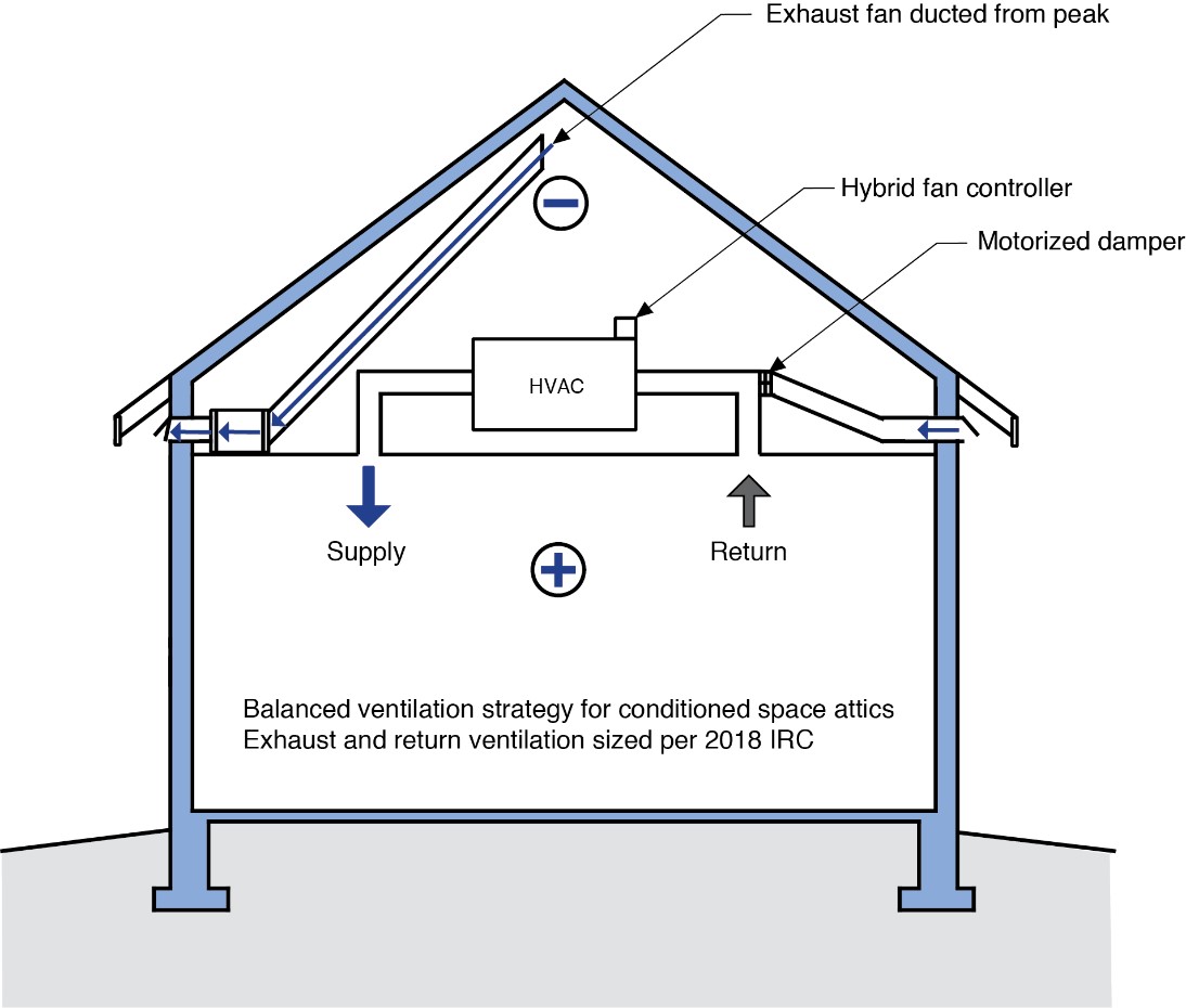
    One of the best ways to remove moisture from the attic space is to provide air change. With the air change approach, air is exhausted from the peak of the attic using an exhaust fan ducted to the exterior. This creates a slight negative pressure in the attic and air is drawn from the house below.  To create “balanced” ventilation in the house, supply air is provided from the outside to the return side of the air handler (Figure 3). The quantity of this air flow should be based on the International Residential Code – 2018. To prevent over-ventilation or under-ventilation, a motorized damper is installed at the outdoor air supply of the system. The operation of the motorized damper is coupled or linked to the operation of the attic exhaust fan – the attic exhaust fan operates only when the motorized damper is open and the HVAC system blower is operating.  

    Another approach is to provide balanced ventilation with heat recover or energy recovery. When heat recovery or energy recovery is used, exhaust air is pulled from the peak of the attic (as in Figure 2) and supply air is provided from the occupied portion of the house.

    A third approach is to provide dehumidification (a “dehumidifier”) to the attic space.

    A fourth approach is to provide ducted supply and ducted return air to the attic space using the HVAC system in the house. With this approach, the attic or roof space is directly coupled to the occupied portion of the house and the moisture control strategy for the house is used to provide moisture control for the attic space. Note that this fourth approach can only be used with spray foams that are not combustible or are covered or protected from fire.

    Because this retrofit will seal the attic, any combustion appliances installed in the attic should be direct-vent sealed-combustion appliances that vent outdoors.

    See the Climate tab for additional important information about vapor retarders in cold climates.

    Balanced ventilation strategy for conditioned attic spaces.
    Figure 3. Balanced ventilation strategy for conditioned attic spaces (Source: Courtesy of Building Science Corporation).


    In Figures 4 through 6, the roof cladding is represented as shingles, but other roof claddings would be acceptable provided that the attachment of the roof cladding does not result in horizontal obstructions on the water control layer beneath the cladding.

    Sloped roof with cavity spray foam insulation sprayed on underside of roof deck and covered with sprayed-on thermal or ignition barrier coating.
    Figure 4. Sloped roof with cavity spray foam insulation sprayed on underside of roof deck and covered with a sprayed-on thermal or ignition barrier coating over the spray polyurethane foam insulation if necessary based on the material properties of the spray polyurethane foam or as required by code (Source: Courtesy of Building Science Corporation).


    Sloped roof with cavity spray foam insulation, strapping, and gypsum board thermal barrier.
    Figure 5. Sloped roof with cavity spray polyurethane foam insulation, strapping, and gypsum board thermal barrier and ignition barrier (Source: Courtesy of Building Science Corporation).


    lat roof with cavity spray foam plus loose-fill insulation and gypsum board thermal barrier.
    Figure 6. Flat roof with cavity spray polyurethane foam plus additional non-spray foam insulation covered by a gypsum board thermal barrier and ignition barrier (Source: Courtesy of Building Science Corporation).


    How to Insulate a Roof from the Interior

    1. Inspect the integrity of the roof system (roofing membrane or shingles).  Check for any deficiencies, water damage, active leaks, etc.  Proceed only if needed repairs are performed.
    2. If there is an interior finish at the roofline (cathedral ceiling), remove the interior finish (plaster or gypsum board).  Check the roof framing for any deficiencies, rot, water damage, active leaks, insect damage, etc.  Proceed only if needed repairs are performed.  Based on the findings, revise the roof assembly and review specific detailing as needed.  Follow the minimum requirements of the current adopted building code regarding the wood roof framing construction.
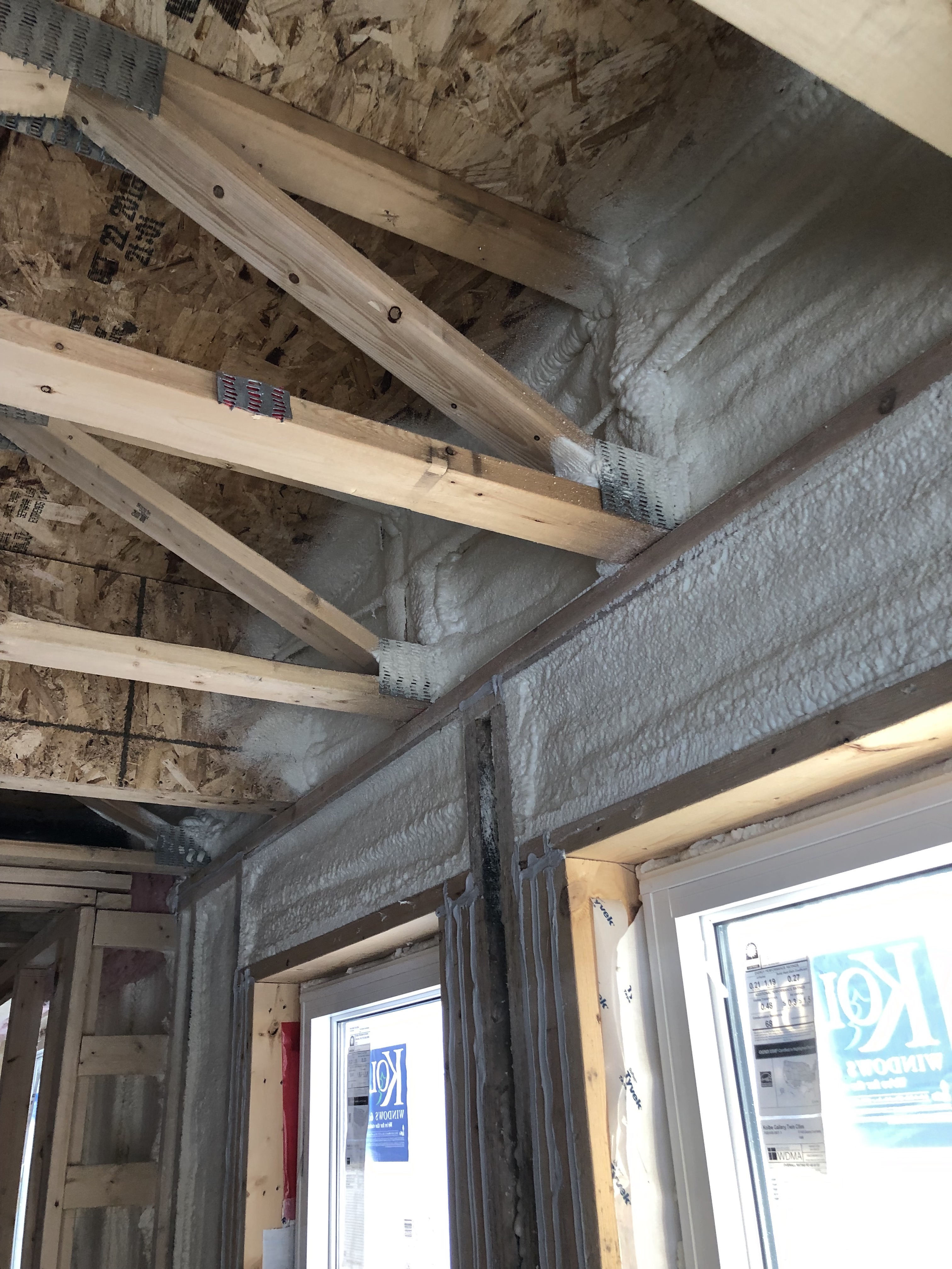
    3. Block the soffit vents; a typical detail is to provide 2x blocking or extended wall sheathing at the exterior wall line, to provide a substrate for the spray foam.
    4. Apply spray foam at the underside of the roof sheathing and at the wall perimeter to create an air barrier connecting the wall to the roof, and to provide adequate thermal resistance to prevent condensation.  All attic gable end walls now separate interior from exterior conditions and must be insulated and air sealed.  A typical approach is to insulate the gable end walls with the same spray foam used at the roofline. Prior to installing spray foam, ensure the decking is dry and free of debris and dust to ensure adequate adhesion.  Install additional non-spray-polyurethane foam insulation over the layer of spray polyurethane foam in wall and roof cavities if desired.
    5. Install a sprayed-on thermal or ignition barrier coating over the spray polyurethane foam insulation if necessary based on the material properties of the spray polyurethane foam or as required by code.  Note that not all spray polyurethane foams require thermal or ignition barriers.  (See AY-126 Thermal and Ignition Barriers For The SPF Industry).   
    6. Inspect and air seal all penetrations through the attic floor.
    7. Provide controlled ventilation, balanced ventilation with heat recovery, install a dehumidifier, or supply conditioned house air to the attic as described above.
    8.  Ensure the home has good ventilation and that any combustion appliances installed in the attic are direct-vent sealed combustion appliances that vent outside.
    Success
    Ensuring Success

    Inspect the existing roof system, including the roofing membrane or shingles and framing, for any deficiencies and make any corrections if necessary. Consider roof replacement if roof is near end of service life.

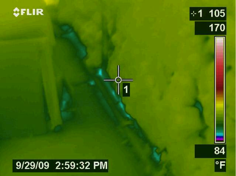
    Monitor the moisture content of the roof sheathing, when possible, during the construction process. Take measurements before the installation of the air-impermeable insulation to help ensure that the roof deck is dry enough to be covered with spray-foam insulation.

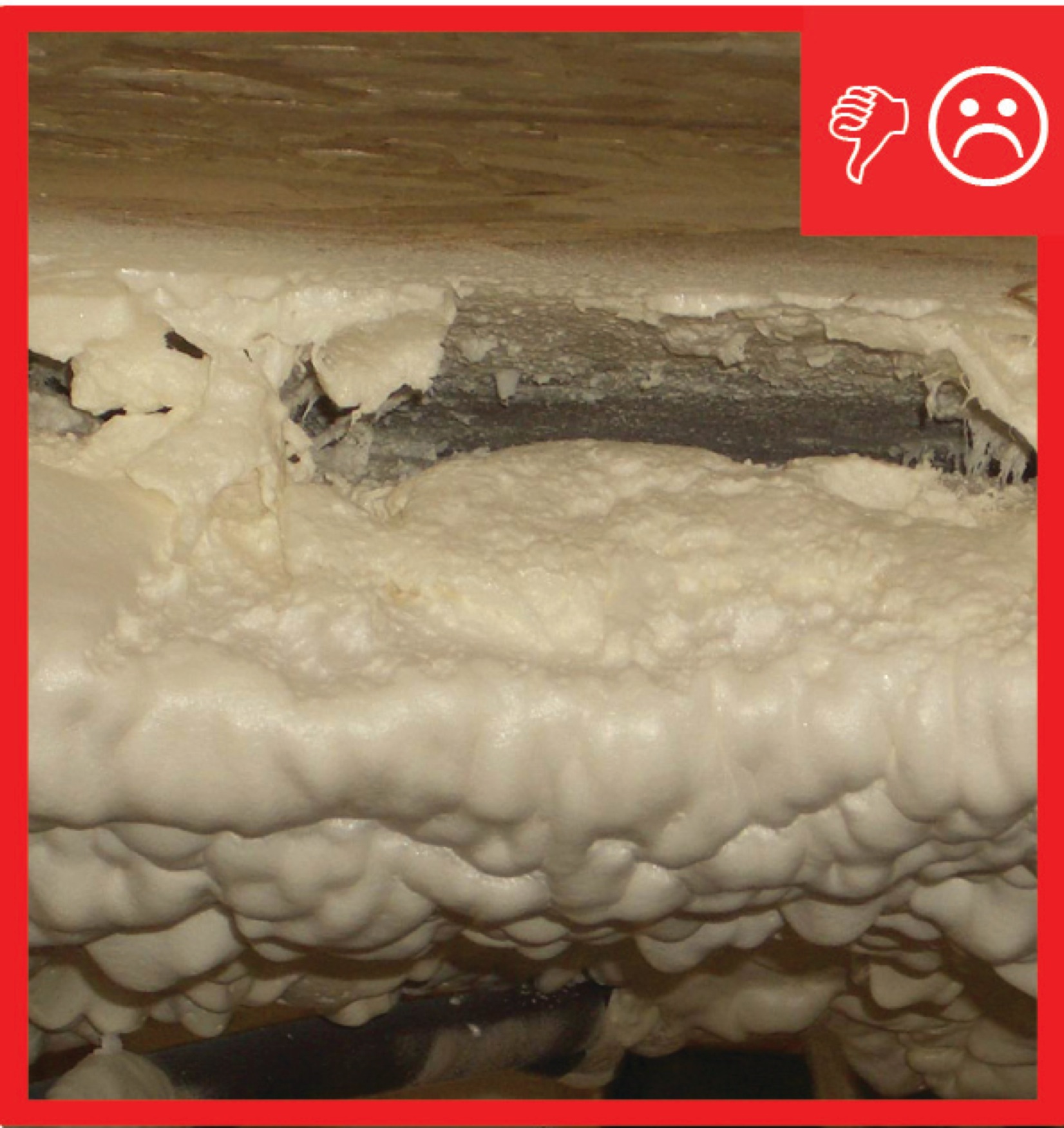
    Spray polyurethane foam is a material that is essentially “manufactured” when applied at the building site. Given the importance of this material’s performance, quality control measures should be set in place. Some key issues include moisture content and temperature of the substrate, applied spray foam layer or “lift” thickness, ratios of the two spray foam components during application, and storage/handling of spray foam components.  Further information is available at the Spray Polyurethane Foam Alliance.

    Apply insulation to a debris- and dust-free surface to provide adequate thermal resistance to prevent condensation.

    Apply insulation to the levels specified in the current adopted building and energy codes.

    Given the increased airtightness associated with this retrofit, combustion safety and controlled mechanical ventilation upgrades are required to maintain acceptable indoor air quality.

    Climate
    Climate

    In high wind regions – particularly in coastal areas – wind-driven rain is a problem with vented attic and vented roof assemblies. Additionally, during high wind events, vented soffits have been known to collapse leading to building pressurization and window blowout and roof loss due to increased uplift. Unvented conditioned attics and roofs are safer during hurricanes; they outperform vented attics and roofs principally due to the robustness of their soffit construction.

    In coastal areas, salt spray and corrosion are a major concern with steel frames, metal roof trusses, and truss plate connectors in vented attics and vented roofs. This is not an issue with unvented, conditioned attics and roofs.

    If seeking to qualify an existing home to the criteria of the IBHS Fortified Home Hurricane and High Wind standards, the criteria to seal the roof deck can be met by applying closed-cell spray urethane-based foam adhesives along the joints between the roof sheathing and roof framing members as well as along all seams between the roof sheathing panels.

    In flood areas, provision should be provided to allow access to roof tops if refuge, rescue, and evacuation becomes necessary. This can be provided by installing operable skylights or dormers or other alternatives that allow egress.

    The roof assembly should be designed for a specific hygrothermal region, rain exposure zone, and climate.  

    The map in Figure 1 shows the climate zones for states that have adopted energy codes equivalent to the International Energy Conservation Code (IECC) 2009, 12, 15, and 18. The map in Figure 2 shows the climate zones for states that have adopted energy codes equivalent to the IECC 2021. Climate zone-specific requirements specified in the IECC are shown in the Compliance Tab of this guide. 


    Climate Zone Map from IECC 2009, 12, 15, and 18.

    Figure 1. Climate Zone Map from IECC 2009, 12, 15, and 18 (Source: 2012 IECC).


    Climate Zone Map from IECC 2021.

    Figure 2. Climate Zone Map from IECC 2021 (Source: 2021 IECC).


    In cold climates, interior relative humidity can directly affect the sheathing moisture content with open-cell or closed-cell spray-foamed roofs. Building Science Corporation recommends that winter-time relative humidity in homes located in Climate Zones 6, 7, or 8 should be maintained below 35% (Grin, Smegal, and Lstiburek 2013).

    Open-cell spray foam should be a Class II vapor retarder or be coated with a Class II vapor retarder in cold climates 5, 6, 7, and 8 (2018 IRC R806.5). Class I vapor retarders should not be installed on the ceiling side of any spray foam installed on the underside of the roof decking in any climate zone as the vapor retarder will prevent drying to the inside in case of a roof leak.

    The design should be based on the minimum requirements for the currently adopted building code and energy code.  Additionally, it is important to maintain a sufficient ratio of air- and vapor-impermeable insulation to air- and vapor-permeable insulation within the roof assembly. In colder climate zones, the amount of air- and vapor-impermeable insulation needed to control condensation increases.

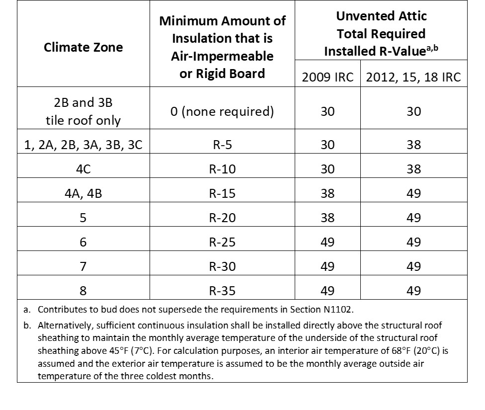
    Table 1 below provides information on the code-recommended minimum levels of thermal resistance and the minimum levels of air-impermeable insulation for condensation control specified in Table R806.5 Insulation for Condensation Control of the 2018 IRC.  For further explanation, see IRC FAQ: Conditioned Attics.

    Table 1 shows an insulation ratio – the R-value on the top of the roof sheathing compared to the total R-value of the insulation.  The ratio changes based on climate severity. The 2018 IRC specifies the ratios based on climate zone. Note how the ratio changes from approximately 10% to 70% as the assembly moves from hot climates to cold climates. Also note that in Climate Zones 5, 6, 7, and 8, the air-impermeable insulation (“SPF”) must either be a Class II vapor retarder or shall have a Class II vapor retarder coating or covering in direct contact with the underside of the air-impermeable insulation.


    IRC 2009-18 Insulation Permeability Table TG 4-8-20

    Table 1. Air-Impermeable Insulation for Condensation Control in Unvented Attics - Based on Table 806.5 of the 2018 International Residential Code (Source: 2018 IRC).


    2018 International Residential Code (IRC)

    The IRC Section R202 defines vapor retarder classes.  A vapor retarder is defined as “a measure of the ability of a material or assembly to limit the amount of moisture that passes through that material or assembly.”  Vapor retarder classes are defined by the IRC using the desiccant method with Procedure A of ASTM E96. These classes are:

    • Class I: 0.1 perm or less
    • Class II: 0.1 perm to 1.0 perm
    • Class III: 1 perm to 10 perms.

    The 2018 IRC Section R806.5 requires the following: In Climate Zones 5, 6, 7, and 8, any air-impermeable insulation shall be a Class II vapor retarder or shall have a Class II vapor retarder coating or covering in direct contact with the underside of the insulation.

    The IRC for Climate Zones 1, 2, 3, or 4 requires that a Class I vapor control layer not be installed on the interior side of the assembly.  This is to prevent inward-driven moisture from being trapped in the wall assembly.  Installing a low-permeance vapor control layer on the interior in a cooling-dominated climate can quickly deteriorate the assembly.


    Training
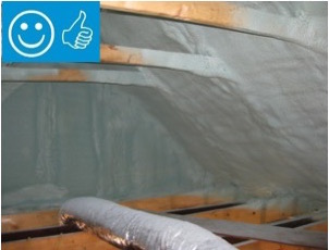
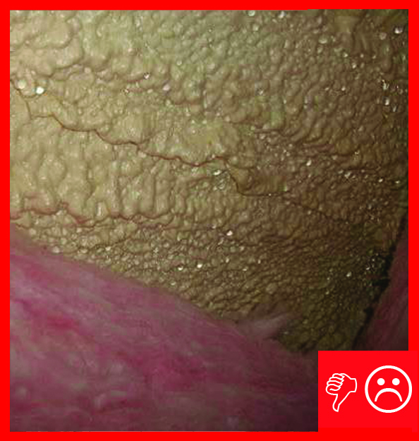
    Right and Wrong Images
    Image
    Right - Spray foam insulation has been sprayed onto the underside of the sloped roof and the gable end wall to provide a sealed, insulated attic for housing the HVAC ducts
    Right - Spray foam insulation has been sprayed onto the underside of the sloped roof and the gable end wall to provide a sealed, insulated attic for housing the HVAC ducts
    Image
    Right - This new sealed attic has 5.5 inches (R-20) of spray foam insulation along the underside of the roof deck providing a conditioned attic space for the heating and cooling ducts.
    Right - This new sealed attic has 5.5 inches (R-20) of spray foam insulation along the underside of the roof deck providing a conditioned attic space for the heating and cooling ducts.
    Image
    Right - Open-cell polyurethane spray foam to R-28 on underside of roof turns new attic into conditioned space for HVAC.
    Right - Open-cell polyurethane spray foam to R-28 on underside of roof turns new attic into conditioned space for HVAC.
    Image
    Right – R-25 of open-cell spray foam lines this new home’s attic ceiling, to protect HVAC ducts from heat and cold.
    Right – R-25 of open-cell spray foam lines this new home’s attic ceiling, to protect HVAC ducts from heat and cold.
    Image
    Wrong: Closed-cell spray foam roof insulation was not thick enough to meet IRC levels so the foam surface is colder than the dew point of the interior air and condensation formed on surface of the foam
    Wrong: Closed-cell spray foam roof insulation was not thick enough to meet IRC levels so the foam surface is colder than the dew point of the interior air and condensation formed on surface of the foam
    Image
    Right – Spray foam insulates the unvented attic.
    Right – Spray foam insulates the unvented attic.
    Image
    Right – Open-cell spray foam fills the attic floor joists.
    Right – Open-cell spray foam fills the attic floor joists.
    Image
    Right – This attic knee wall and the floor joist cavity openings beneath it are being sealed and insulated with spray foam.
    Right – This attic knee wall and the floor joist cavity openings beneath it are being sealed and insulated with spray foam.
    Image
    Right-- IR photo shows how effectively spray foam insulated/air sealed attic kneewall and the floor cavities under kneewall
    Right-- IR photo shows how effectively spray foam insulated/air sealed attic kneewall and the floor cavities under kneewall
    Image
    Wrong – Spray foam installed with voids
    Wrong – Spray foam installed with voids
    Image
    Wrong: Closed-cell spray foam roof insulation was not thick enough to meet IRC levels so the foam surface is colder than the dew point of the interior air and condensation formed on surface of the foam
    Wrong: Closed-cell spray foam roof insulation was not thick enough to meet IRC levels so the foam surface is colder than the dew point of the interior air and condensation formed on surface of the foam
    Image
    Right - Spray foam fills the walls and rim joists to air seal and insulate while caulk seals the framing joints.
    Right - Spray foam fills the walls and rim joists to air seal and insulate while caulk seals the framing joints.
    Image
    Right – Open-cell spray foam fills the walls and cathedral ceilings of this multi-story home.
    Right – Open-cell spray foam fills the walls and cathedral ceilings of this multi-story home.
    Image
    Right – Open-cell spray foam is installed over closed-cell spray foam in this hybrid approach to achieve adequate attic ventilation while allowing some vapor permeability.
    Right – Open-cell spray foam is installed over closed-cell spray foam in this hybrid approach to achieve adequate attic ventilation while allowing some vapor permeability.
    Image
    Right – Spray foam insulates the unvented attic.
    Right – Spray foam insulates the unvented attic.
    Presentations
    Videos
    CAD
    CAD Files
    IBHS Fortified Home Spray Foam Sealed Roof Deck
    IBHS Fortified Home Spray Foam Sealed Roof Deck
    Download: PDF
    Compliance

    Compliance

    The Compliance tab contains both program and code information. Code language is excerpted and summarized below. For exact code language, refer to the applicable code, which may require purchase from the publisher. While we continually update our database, links may have changed since posting. Please contact our webmaster if you find broken links.


    ENERGY STAR Single-Family New Homes, Version 3/3.1 (Rev. 11)

    ENERGY STAR Single-Family New Homes requires that ceiling, wall, floor, and slab insulation levels meet or exceed those specified in the 2009 International Energy Conservation Code (IECC) with some alternatives and exceptions, and achieve Grade 1 installation per RESNET Standards (see 2009 and 2012 IECC Code Level Insulation – ENERGY STAR Requirements and Insulation Installation (RESNET Grade 1) - Part 1 and Insulation Installation (RESNET Grade 1) - Part 2. If the state or local residential building energy code requires higher insulation levels than those specified in the 2009 IECC, you must meet or exceed the locally mandated requirements. 

    National Rater Design Review Checklist

    3. High-Performance Insulation.
    3.1 Specified ceiling, wall, floor, and slab insulation levels comply with one of the following options:
    3.1.1 Meets or exceeds 2009 IECC levels5, 6, 7 OR;
    3.1.2 Achieves ≤ 133% of the total UA resulting from the U-factors in 2009 IECC Table 402.1.3, per guidance in Footnote 5d, AND specified home infiltration does not exceed the following:6, 7

    • 3 ACH50 in CZs 1, 2
    • 2.5 ACH50 in CZs 3, 4
    • 2 ACH50 in CZs 5, 6, 7
    • 1.5 ACH50 in CZ 8

    Footnote 5) Specified levels shall meet or exceed the component insulation levels in 2009 IECC Table 402.1.1. The following exceptions apply:
    a. Steel-frame ceilings, walls, and floors shall meet the insulation levels of 2009 IECC Table 402.2.5. In CZ 1 and 2, the continuous insulation requirements in this table shall be permitted to be reduced to R-3 for steel-frame wall assemblies with studs spaced at 24 in. on center. This exception shall not apply if the alternative calculations in d) are used;
    b. For ceilings with attic spaces, R-30 shall satisfy the requirement for R-38 and R-38 shall satisfy the requirement for R-49 wherever the full height of uncompressed insulation at the lower R-value extends over the wall top plate at the eaves. This exemption shall not apply if the alternative calculations in d) are used;
    c. For ceilings without attic spaces, R-30 shall satisfy the requirement for any required value above R-30 if the design of the roof / ceiling assembly does not provide sufficient space for the required insulation value. This exemption shall be limited to 500 sq. ft. or 20% of the total insulated ceiling area, whichever is less. This exemption shall not apply if the alternative calculations in d) are used;
    d. An alternative equivalent U-factor or total UA calculation may also be used to demonstrate compliance, as follows: An assembly with a U-factor equal or less than specified in 2009 IECC Table 402.1.3 complies. A total building thermal envelope UA that is less than or equal to the total UA resulting from the U-factors in Table 402.1.3 also complies. The performance of all components (i.e., ceilings, walls, floors, slabs, and fenestration) can be traded off using the UA approach. Note that Items 3.1 through 3.3 of the National Rater Field Checklist shall be met regardless of the UA tradeoffs calculated. The UA calculation shall be done using a method consistent with the ASHRAE Handbook of Fundamentals and shall include the thermal bridging effects of framing materials. The calculation for a steel-frame envelope assembly shall use the ASHRAE zone method or a method providing equivalent results, and not a series-parallel path calculation method.

    Footnote 6) Consistent with the 2009 IECC, slab edge insulation is only required for slab-on-grade floors with a floor surface less than 12 inches below grade. Slab insulation shall extend to the top of the slab to provide a complete thermal break. If the top edge of the insulation is installed between the exterior wall and the edge of the interior slab, it shall be permitted to be cut at a 45-degree angle away from the exterior wall. Alternatively, the thermal break is permitted to be created using ≥ R-3 rigid insulation on top of an existing slab (e.g., in a home undergoing a gut rehabilitation). In such cases, up to 10% of the slab surface is permitted to not be insulated (e.g., for sleepers, for sill plates). Insulation installed on top of slab shall be covered by a durable floor surface (e.g., hardwood, tile, carpet).

    Footnote 7) Where an insulated wall separates a garage, patio, porch, or other unconditioned space from the conditioned space of the house, slab insulation shall also be installed at this interface to provide a thermal break between the conditioned and unconditioned slab. Where specific details cannot meet this requirement, partners shall provide the detail to EPA to request an exemption prior to the home’s certification. EPA will compile exempted details and work with industry to develop feasible details for use in future revisions to the program. A list of currently exempted details is available at: energystar.gov/slabedge.

    National Water Management System Builder Requirements

    3. Water-Managed Roof Assembly.
    3.1 Step and kick-out flashing at all roof-wall intersections, extending ≥ 4” on wall surface above roof deck and integrated shingle-style with drainage plane above; boot / collar flashing at all roof penetrations.13
    3.2 For homes that don’t have a slab-on-grade foundation and do have expansive or collapsible soils, gutters & downspouts provided that empty to lateral piping that discharges water on sloping final grade ≥ 5 ft. from foundation, or to underground catchment system not connected to the foundation drain system that discharges water ≥ 10 ft. from foundation. Alternatives & exemptions in Footnote.4, 14, 15
    3.3 Self-adhering polymer-modified bituminous membrane at all valleys & roof deck penetrations.4, 16
    3.4 In 2009 IECC Climate Zones 5 & higher, self-adhering polymer-modified bituminous membrane over sheathing at eaves from the edge of the roof line to > 2 ft. up roof deck from the interior plane of the exterior wall.4, 16

    Footnote 4) Not required in Dry (B) climates as shown in 2009 IECC Figure 301.1 and Table 301.1.

    Footnote 13) Intersecting wall siding shall terminate 1 in. above the roof or higher, per manufacturer's recommendations. Continuous flashing shall be installed in place of step flashing for metal and rubber membrane roofs.

    Footnote 14) The assessment of whether the soil is expansive or collapsible shall be completed by a certified hydrologist, soil scientist, or engineer.

    Footnote 15) Any of the following are permitted to be used as alternatives to Item 3.2: a) a roof design that deposits rainwater to a grade-level rock bed with a waterproof liner and a lateral drain pipe that meets discharge requirements per Item 3.2; b) a rainwater harvesting system that drains overflow to meet discharge requirements per Item 3.2; or c) a continuous rubber membrane (e.g. EPDM) that is aligned with the foundation wall from final grade to ≥ 8 in. below grade and then slopes ≥ 0.5 in. per ft. away from the home for at least 5 ft., with Group I Soils (as defined in Footnote 9) covering the membrane to within 3 in. of final grade.

    Footnote 16) As an alternative, any applicable option in 2009 IRC Section R905.2.8.2 is permitted to be used to meet Item 3.3 and any option in 2009 IRC Section R905.2.7.1 is permitted to be used to meet Item 3.4. EPA recommends, but does not require, that products meet ASTM D1970. In addition, any option in 2009 IRC Section R905.13 is permitted to be used to meet either Item 3.3 or 3.4.

    Please see the ENERGY STAR Single-Family New Homes Implementation Timeline for the program version and revision currently applicable in your state.


    DOE Zero Energy Ready Home (Revision 07)

    Exhibit 1 Mandatory Requirements.
    Exhibit 1, Item 1) Certified under the ENERGY STAR Qualified Homes Program or the ENERGY STAR Multifamily New Construction Program.
    Exhibit 2, Item 2) Ceiling, wall, floor, and slab insulation shall meet or exceed 2015 IECC levels and achieve Grade 1 installation, per RESNET standards. See the guide 2015 IECC Code Level Insulation – DOE Zero Energy Ready Home Requirements for more details.


    2009, 2012, 2015, 2018, and 2021 International Energy Conservation Code (IECC)

    Section 101.4.3 Additions, alterations, renovations or repairs.  Portions of an existing building that are altered in the course of additions, alterations, renovations or repairs must be brought into conformance with the code with the following exceptions applicable to attic/roof retrofit: existing ceiling wall or floor cavities that are exposed provided the cavities exposed are filled with insulation; addition, alteration, renovation or repair projects that do not expose the existing roof, wall or floor cavity; reroofing that does not expose the insulation nor the sheathing.

    Section 101.4.5 (R502.1.2 in 2018, R502.2 in 2021) Change in space conditioning.  This section states that spaces must be brought into full compliance with the new construction requirements if the addition, alteration, renovation or repair changes that space from unconditioned to conditioned space.

    Section 402 Building Thermal Envelope. Table 402.1.1 (R402.1.2 in 2018, R402.1.3 in 2021) indicates the prescriptive requirements for building enclosure components.

    Section 402.4 Air Leakage.  This section indicates that the building thermal envelope (as it is called in the IECC) must be sealed to limit infiltration and that it must be sealed in a manner that is durable allowing for differential expansion and contraction.

    Section 402.2.1 Ceilings with attic spaces. This section indicates that the prescriptive requirement for R-38 ceiling insulations is deemed to be met by R-30 insulation when the R-30 insulation extends over the wall top plate at eaves and when the insulation is at full loft and uncompressed over the wall top plate at eaves.  Similarly, R-38 insulation is recognized to satisfy the requirement for R-49 insulation when R-38 insulation extends over the wall top plate at eaves and when the insulation is at full loft and uncompressed over the wall top plate at eaves. (In the 2021 IECC, this reduction is extended to the requirement for R-60 insulation, stating that R-45 can satisfy the requirement where insulation extends over the wall top plate at eaves and when the insulation is at full loft and uncompressed over the wall top plate at eaves. )

    Retrofit:  2009, 2012, 2015, 2018,  and 2021 IECC

    Section R101.4.3 (in 2009 and 2012). Additions, alterations, renovations, or repairs shall conform to the provisions of this code, without requiring the unaltered portions of the existing building to comply with this code. (See code for additional requirements and exceptions.)

    Chapter 5 (in 2015, 2018, 2021). The provisions of this chapter shall control the alteration, repair, addition, and change of occupancy of existing buildings and structures.


    2009 International Residential Code (IRC)

    R316.4 Thermal barrier. This section addresses the thermal barrier requirements when foam plastic is used and its installation

    R316.5.3 Attics. This section lists the exceptions to the use of a thermal barrier, including ignition barrier options for foam plastic insulation. 

    Section R806.5 Unvented attic assemblies.  This section outlines the conditions for unvented attic/roof assemblies.  Note that table R806.5 indicates the amount of insulation above the roof deck or air impermeable insulation below the roof deck required for condensation control assuming minimum required total insulation as indicated in Section N1102 Building Thermal Envelope.  Higher R-value assemblies will require a proportionally larger amount of air impermeable insulation below the roof deck or insulation above the roof deck for condensation control.

    Section R807.1 Attic access.  An attic access is required where the ceiling or roof construction is combustible and where the attic area is more than 30 sf and the height between the ceiling framing and roof framing is more than 30”.  Refer to specific language of this section for required dimensions of the access.

    Section R901 Roof Assemblies.  This section outlines the design, materials, construction and quality of roof assemblies.

    Section N1102 Building Thermal Envelope. Table N1102.1 indicates the prescriptive requirements for building enclosure components.

    Section N1102.4 Air Leakage.  This section indicates that the building thermal envelope (as it is called in the IRC) must be sealed to limit infiltration and that it must be sealed in a manner that is durable allowing for differential expansion and contraction.

    2012, 20152018, and 2021 IRC

    R316.4 Thermal barrier. This section addresses the thermal barrier requirements when foam plastic is used and its installation.  A thermal barrier may be required to be installed – depending on the material properties of the spray foam - to separate the spray foam from interior living spaces, with some exceptions such as attics and crawlspaces not used for living or storage space, sill plates and headers, and certain other exceptions defined in code. An approved thermal barrier is one that is equal in fire resistance to 12.7 mm (1/2 inch) gypsum wallboard or has undergone approved testing as described in the code.

    R316.5.3 Attics. This section lists the exceptions to the use of a thermal barrier, including ignition barrier options for foam plastic insulation. Note that not all spray foams require an ignition barrier.  The IRC permits the use of an ignition barrier as an alternative to installing a thermal barrier in attics and crawlspaces where entry is made only for repairs and maintenance (IRC), provided the SPF is covered with a prescriptive ignition barrier such as 

    • 1 ½-inch-thick (38 mm) mineral fiber insulation, 
    • 1/4-inch-thick (6.4 mm) wood structural panels;
    • 3/8-inch (9.5 mm) particleboard (1/4-inch thick under the IBC)
    • 1/4-inch (6.4 mm) hardboard;
    • 3/8-inch (9.5 mm) gypsum board;
    • Corrosion-resistant steel having a base metal thickness of 0.016 inch (0.406 mm);
    • 1 1/2 inch-thick (38 mm) cellulose insulation;
    • ¼ inch (6.4 mm) fiber-cement panel, soffit, or backer board.

    Section R806.5 Unvented attic assemblies.  This section outlines the conditions for unvented attic/roof assemblies.  Note that table R806.5 indicates the amount of insulation above the roof deck or air impermeable insulation below the roof deck required for condensation control assuming minimum required total insulation as indicated in Section N1102 Building Thermal Envelope.  Higher R-value assemblies will require a proportionally larger amount of air impermeable insulation below the roof deck or insulation above the roof deck for condensation control.

    Section R807.1 Attic access.  An attic access is required where the ceiling or roof construction is combustible and where the attic area is more than 30 sf and the height between the ceiling framing and roof framing is more than 30”.  Refer to specific language of this section for required dimensions of the access.

    Section R901 Roof Assemblies.  This section outlines the design, materials, construction and quality of roof assemblies.

    Section N1102 Building Thermal Envelope. Table N1102.1.1 (N1102.1.2 in 2015, 2018, and 2021 IRC) indicates the prescriptive requirements for building enclosure components.

    Section N1102.4 Air Leakage.  This section indicates that the building thermal envelope (as it is called in the IRC) must be sealed to limit infiltration and that it must be sealed in a manner that is durable allowing for differential expansion and contraction.

    Retrofit:  2009, 2012, 2015, 2018,  and 2021 IRC

    Section R102.7.1 Additions, alterations, or repairs. Additions, alterations, renovations, or repairs shall conform to the provisions of this code, without requiring the unaltered portions of the existing building to comply with the requirements of this code, unless otherwise stated. (See code for additional requirements and exceptions.)

    Appendix J regulates the repair, renovation, alteration, and reconstruction of existing buildings and is intended to encourage their continued safe use.


    More

    More Info.

    Access to some references may require purchase from the publisher. While we continually update our database, links may have changed since posting. Please contact our webmaster if you find broken links.

    Case Studies
    References and Resources*
    Author(s)
    Neuhauser Ken,
    Gates Cathy,
    Pettit Betsy
    Organization(s)
    Building Science Corporation,
    BSC
    Publication Date
    Description
    Guidebook providing useful examples of high performance retrofit techniques for the building enclosure of wood frame residential construction in a cold and somewhat wet climate.
    Author(s)
    Building Science Corporation
    Organization(s)
    BSC
    Publication Date
    Description
    Report discussing how to create livable space in the attic that meets IRC code requirements by either creating a ventilated roof assembly, or and unvented attic assembly.
    Author(s)
    Lstiburek Joseph W
    Organization(s)
    Building Science Corporation,
    BSC
    Publication Date
    Description
    Article describing the difference between conditioned or unvented attics and unconditioned or vented attics.
    Author(s)
    Lstiburek Joseph W
    Organization(s)
    Building Science Corporation,
    BSC
    Publication Date
    Description
    Article outlining the use of spray polyurethane foam in residential buildings.
    Author(s)
    Lstiburek Joseph W
    Organization(s)
    BSC
    Publication Date
    Description
    Article describing issues with condensation in unvented attics insulated with open-cell spray foam.
    *For non-dated media, such as websites, the date listed is the date accessed.
    Contributors to this Guide

    The following authors and organizations contributed to the content in this Guide.

    Building Science Corporation, lead for the Building Science Consortium (BSC), a DOE Building America Research Team

    Sales
    Building Science Measures
    Building Science-to-Sales Translator

    High-R Attic Insulation = High-Efficiency or Ultra-Efficient Attic Insulation

    Image(s)
    Technical Description

    There are two levels of attic insulation: high-efficiency insulation, which meets the 2015 International Energy Conservation Code, and ultra-efficient insulation, which is 25% more efficient than this national code. Using high-efficiency and ultra-efficient insulation along with professional installation (e.g., no gaps, voids, compression, or misalignment with air barriers;  complete air barriers; and minimal thermal bridging) creates conditioned spaces that require very little heating  and cooling, along with even comfort and quiet throughout the house.

    High-Efficiency or Ultra-Efficient Attic Insulation
    Sales Message

    High-efficiency attic insulation helps provide added thermal protection. What this means to you is less wasted energy along with enhanced comfort and quiet. Knowing there is one opportunity to optimize performance during construction, wouldn’t you agree it’s a great opportunity to meet or exceed future codes?

    Last Updated

    Did you find this information helpful?

    If you have questions and/or would like a reply to this feedback, please include your e-mail address in the message.
    This question is for testing whether or not you are a human visitor and to prevent automated spam submissions.