

Scope

Order roof trusses with a notch along the kingpost that allows a duct to be installed above the ceiling plane to account for a raised ceiling or “fur-up” duct chase.
- Construct an air sealed insulated chase to contain the duct.
- Make the duct out of rigid foam or a solid material like drywall or plywood that is air sealed and insulated with rigid foam, spray foam, or batt insulation.
Several trades are critical to the success of this technique:
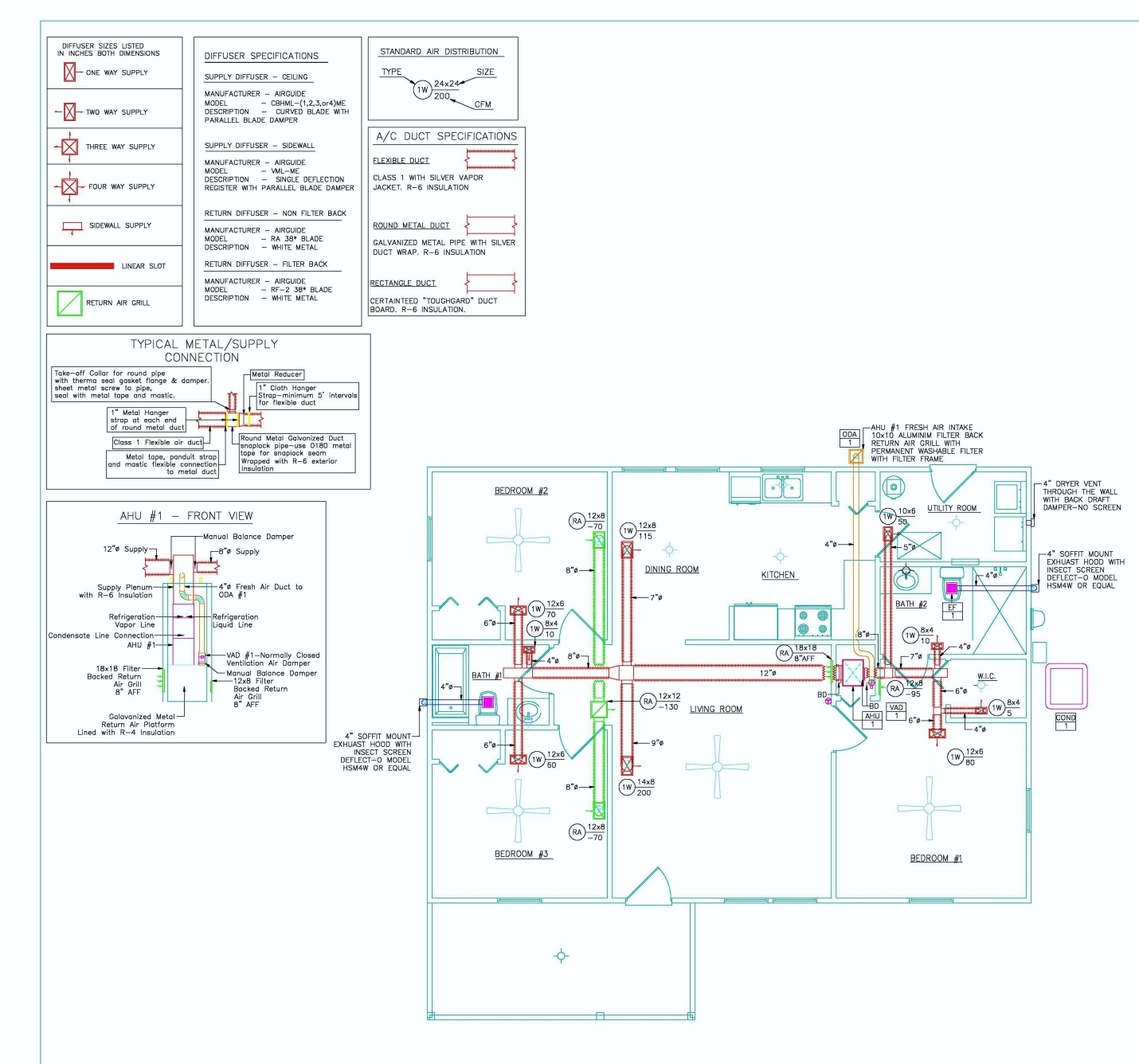
- HVAC Designers - Design a compact duct layout that does not cross load bearing walls. Use ACCA Manual D to determine the duct size needed.
- Framers - Construct any non-load bearing walls that will serve as one side of the chase with a gap of ¾” between the top plate of the wall and the bottom chord of the attic trusses so that drywall can be installed over the top plates to form a continuous ceiling for the duct chase. Construct the remaining duct chase after the chase ceiling drywall is installed.
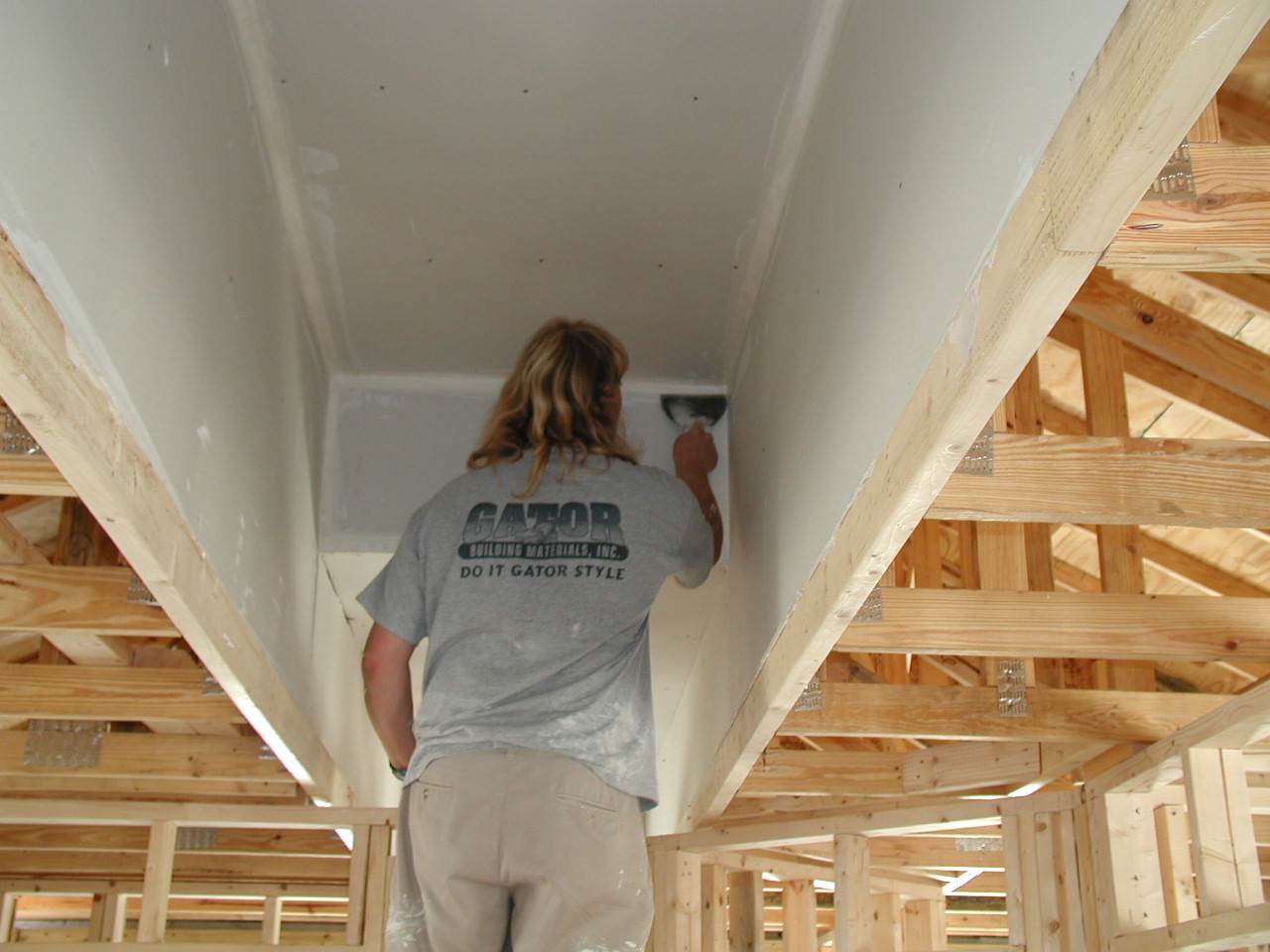
- Drywallers - Install drywall above the duct chase location before framing the chase and before installing the ducting. The remaining drywall in the room will be installed after the duct and chase framing are installed.
- Plumbers and Electricians - Do not use the duct chase as a chase for electrical wiring or plumbing, and do not cut holes through the chase walls.
- All Trades - Participate in a pre-construction meeting to understand construction sequencing steps for this technique, which is further described in the Description tab of this guide.
See the Compliance Tab for links to related codes and standards and voluntary federal energy-efficiency program requirements.
Description
The primary challenge of implementing an interior duct system involves bringing the forced air system, including the air handler, within the dwelling’s air and thermal barrier. This detail must be integrated into the design and construction process. In a raised ceiling or “fur-up” chase installation, a critical detail is the integrity of the air and thermal barriers between the chase and the unconditioned space surrounding it. Also critical for a raised ceiling chase is the truss design. The trusses are typically modified to accommodate the duct chase.
The builder must make a clear and consistent commitment to building an interior duct system. The method and technique of constructing the chase must be clearly documented and communicated to all responsible parties, particularly the drywallers, carpenters, and insulators. The best opportunity to minimize costs while ensuring an aesthetically pleasing outcome is during the preliminary schematic design phase of the home.
The air handler can be located either centrally or at one end of the chase; however, it must be located inside the conditioned space. To avoid long run-out ducts, the chase should trace a path down the center of the house and go to all spaces to be served. Otherwise, small supply runs in unconditioned spaces or excessive chase construction will be required to reach distant rooms.
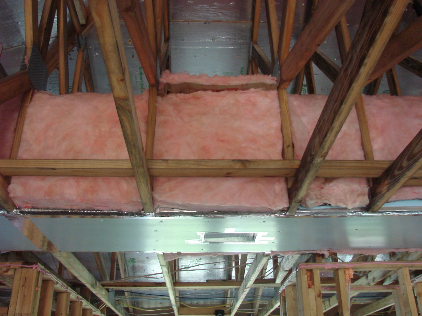
The chase must be air sealed. This can be done with drywall or an insulating material. If drywall is used, the chase must be insulated, which can prove challenging. The chase presents itself in the attic as two knee walls with a small attic floor above them. Typical blown-in insulation is fairly useless in this application, as it soon falls off the chase. A fur-up chase is an excellent candidate for spray-foam insulation. When properly constructed, the chase should be both air tight and thermally isolated from the attic. There could be a temptation to use the chase itself as the duct for the return air system. This is not a recommended practice. See the Compliance tab for more information.
The case study, Raised Ceiling Interior Duct Systems, provides an example of a raised ceiling duct installation.
Instructions for installing a fur-up or raised ceiling duct chase are provided below.
Design and Install a Raised Ceiling Section or Fur-Up Chase for Ducts
- Perform a duct sizing calculation to determine the needed size of the chase to accommodate the duct system.
- Design and lay out the proposed duct system. With information derived from the HVAC designers’ ACCA Manual J and D calculations, the home designer can finalize plans that consider the size requirements and path of the distribution system.
Design the truss package to accommodate a raised ceiling chase. To locate a fur-up chase in a specific design, start by examining the plan for an obvious path. A modified truss package, to allow fur-up chase installation, is only practical when running perpendicular to the truss orientation. In some hip roof situations, the depth of the hip-set can be adjusted to allow for a longer perpendicular run to corner rooms.
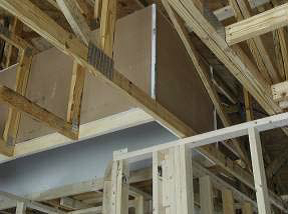
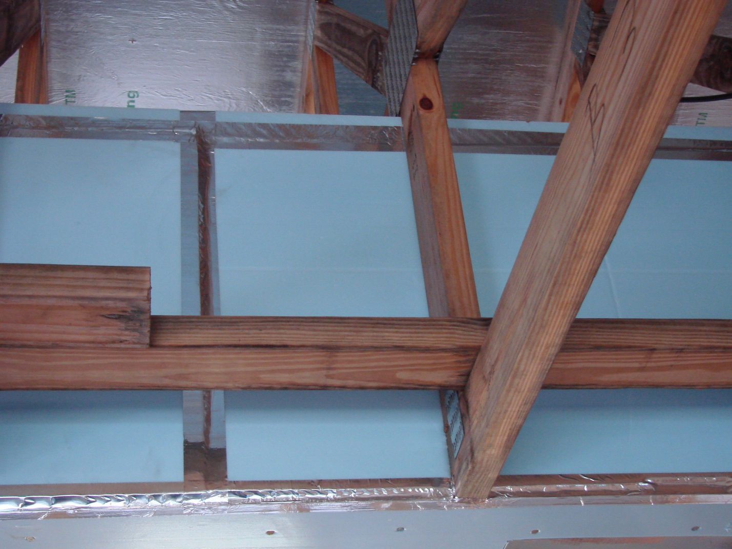
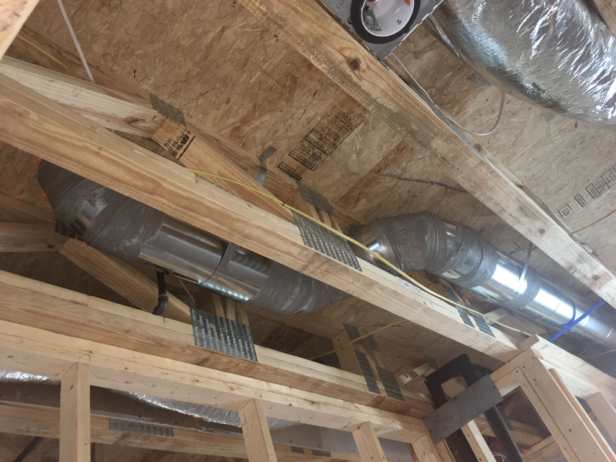
Figure 2. Custom trusses were designed to allow space for a raised duct chase. (Source: Summary of Interior Ducts in New Construction, by FSEC 2011.) - Avoid chase runs that are parallel to the truss orientation. Chases running parallel to the truss orientation will be size-constrained to the width of the truss bay, typically 21 inches when the trusses are set on two-foot centers. With hip roof designs, it may be possible to change the truss orientation, depending on hip orientation, to aid in the lay-out of the fur-up chase and avoid running chases parallel to the truss direction.
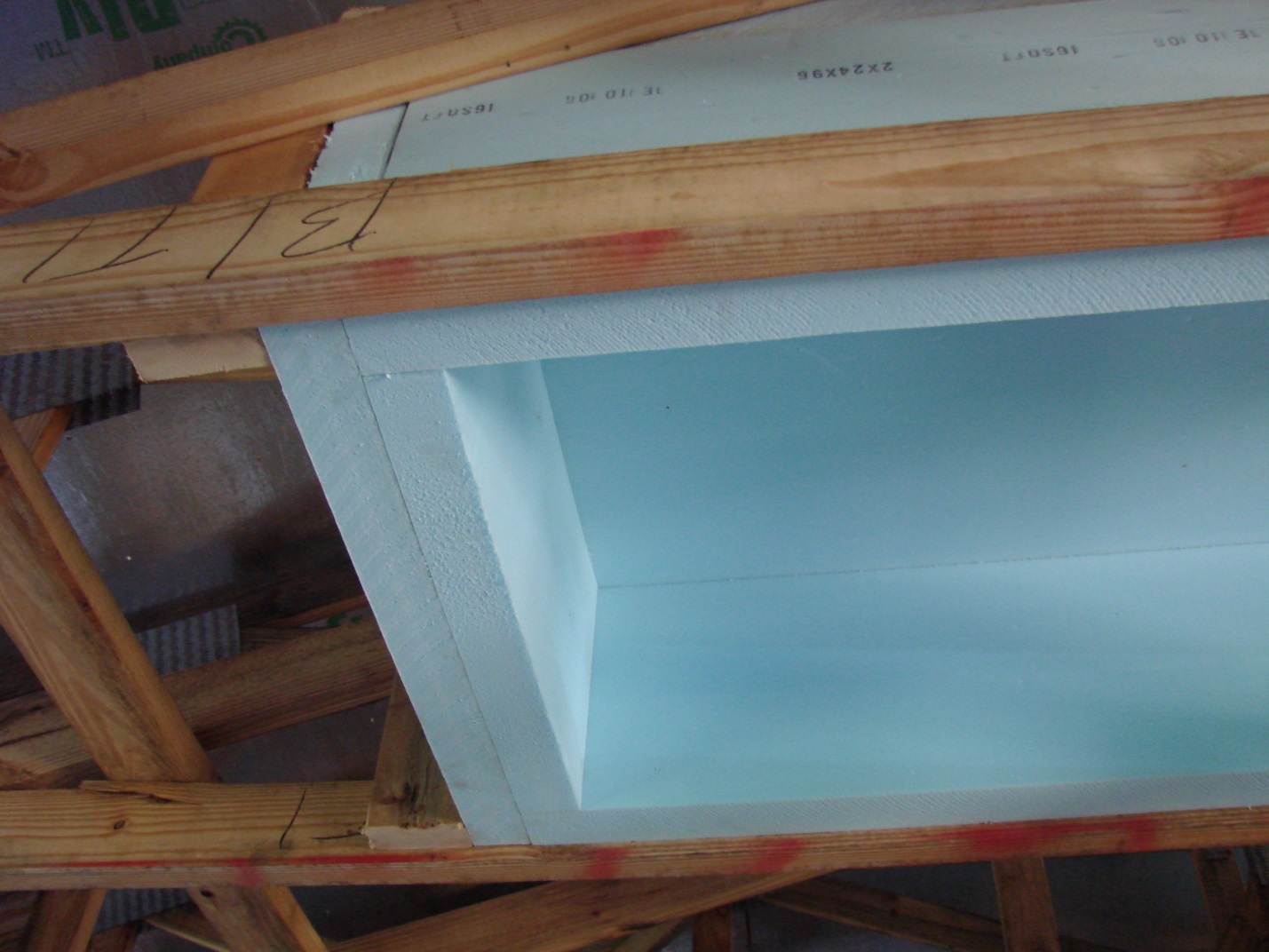
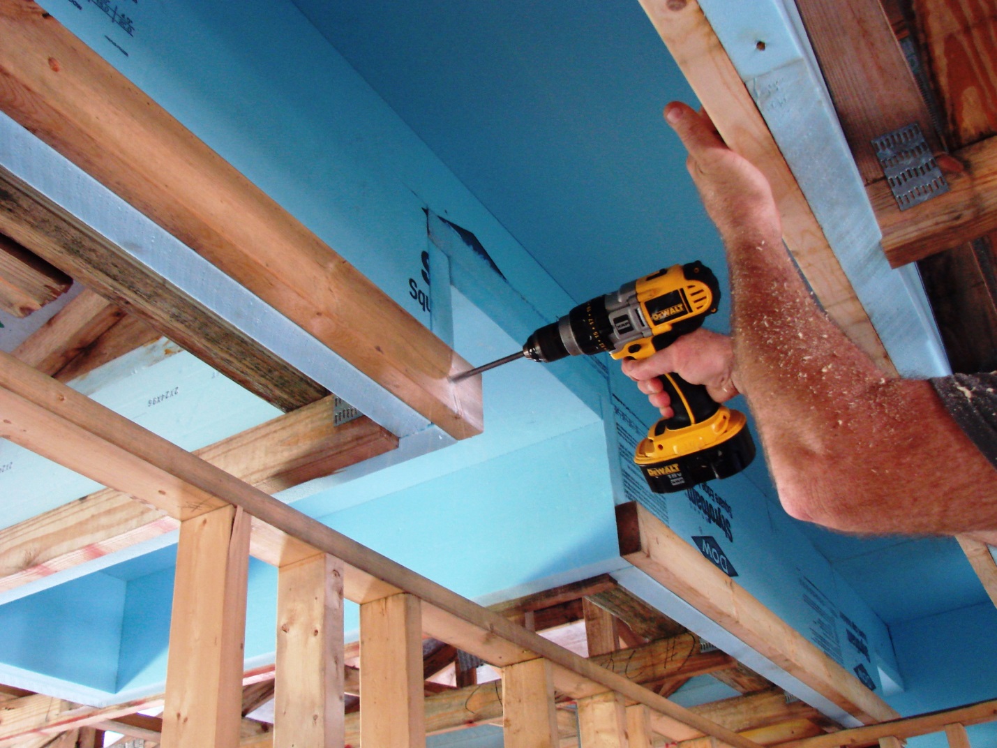
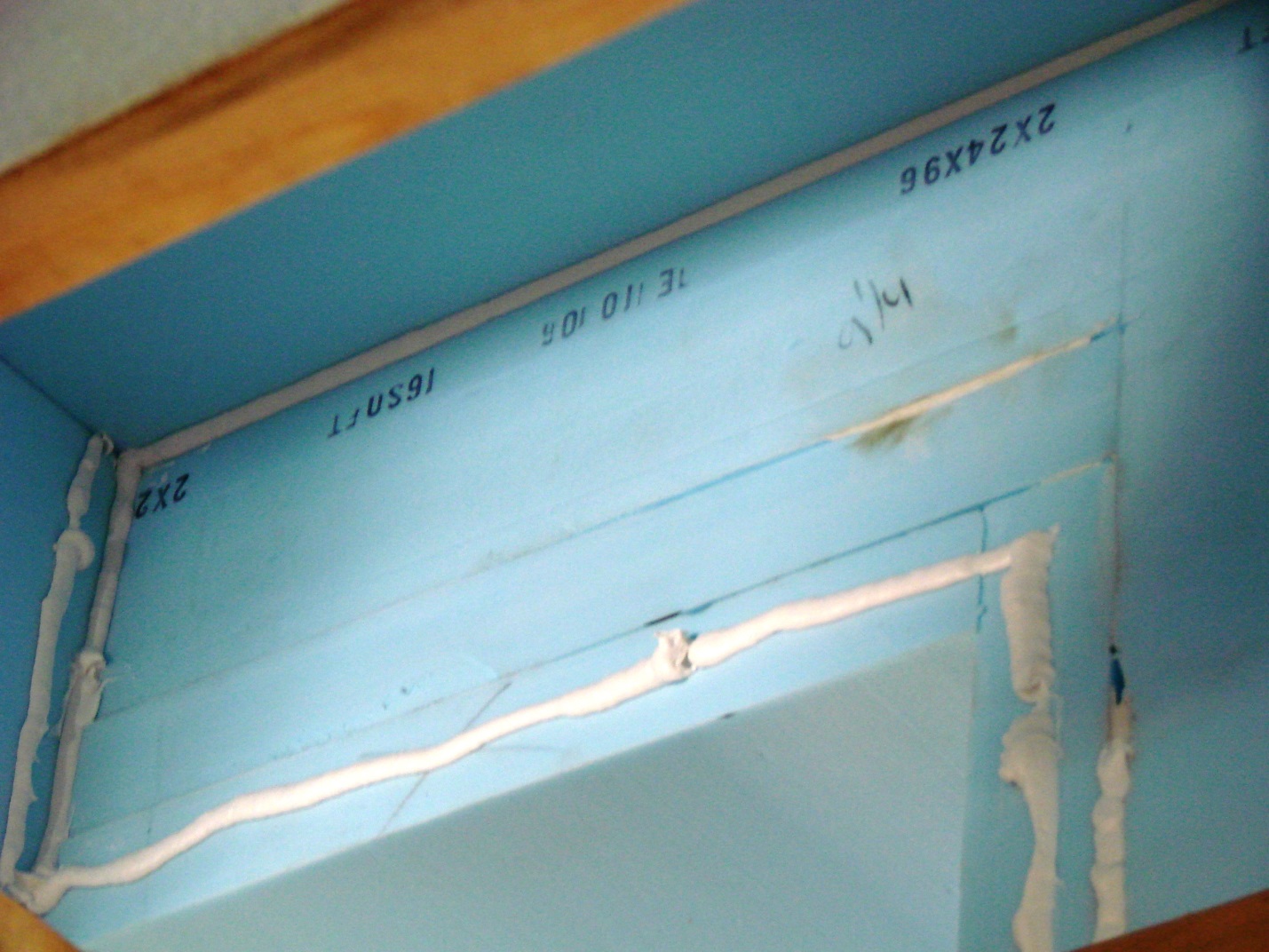
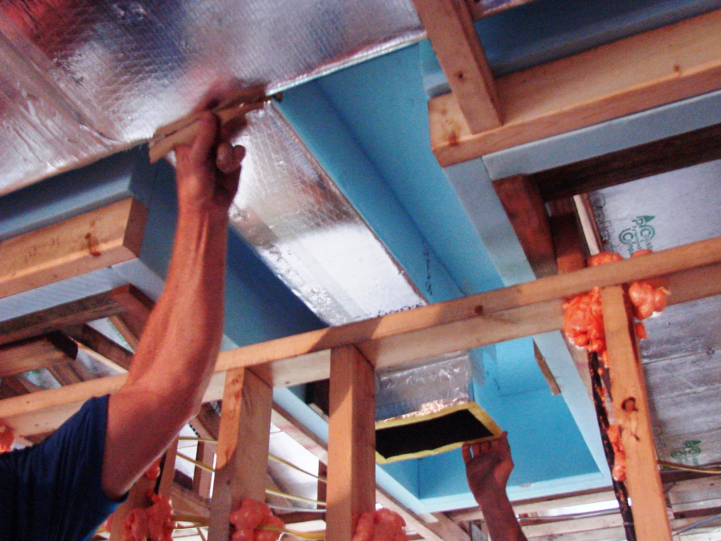
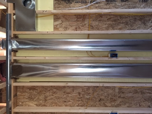
- Commence construction of the chase in the area provided by modified trusses. In this example, the builder decided to use rigid insulation to construct the entire chase due to costs (donated material). The first layer of 2 inch thick rigid insulation is installed and temporarily attached to the trusses, then secured to the truss with a 2 x 4 support at the bottom of the chase with screws. This chase will have a bottom layer of ½ inch rigid insulation installed flush with the bottom chord of the trusses. This detail results in the 2 x 4 support being ½ inch above the bottom chord of the trusses.
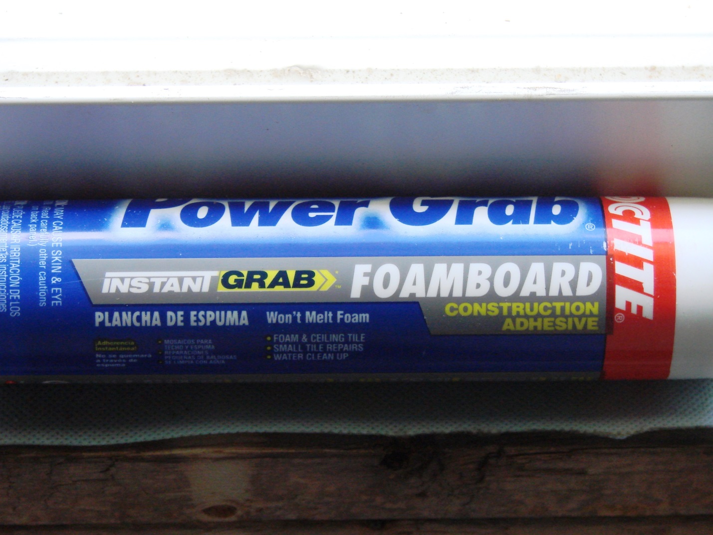
- Seal and secure all seams with the application of a specialty adhesive.
- Finish sealing the first layer of rigid insulation, and prepare for the installation of the second layer of rigid insulation. Foam adhesive is used to attach the second layer of 2-inch rigid insulation, which will increase the chase R-value to R-20. To ensure a leak-free chase, all joints and seams in the chase are staggered.
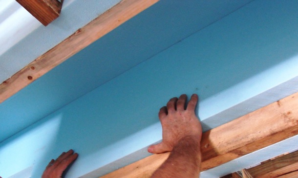
- Install a second layer of rigid insulation. After installing the 2x4 retaining ledge and foam adhesive, the second layer of rigid insulation is installed in the chase, being careful to stagger joints to avoid air leakage.
- Install the preassembled duct system in the chase. Pre-assemble as much of the duct system as possible on the floor to avoid excessive lifts. After finishing the top and sides of the chase, the main trunk of the pre-assembled duct system is lifted into place.

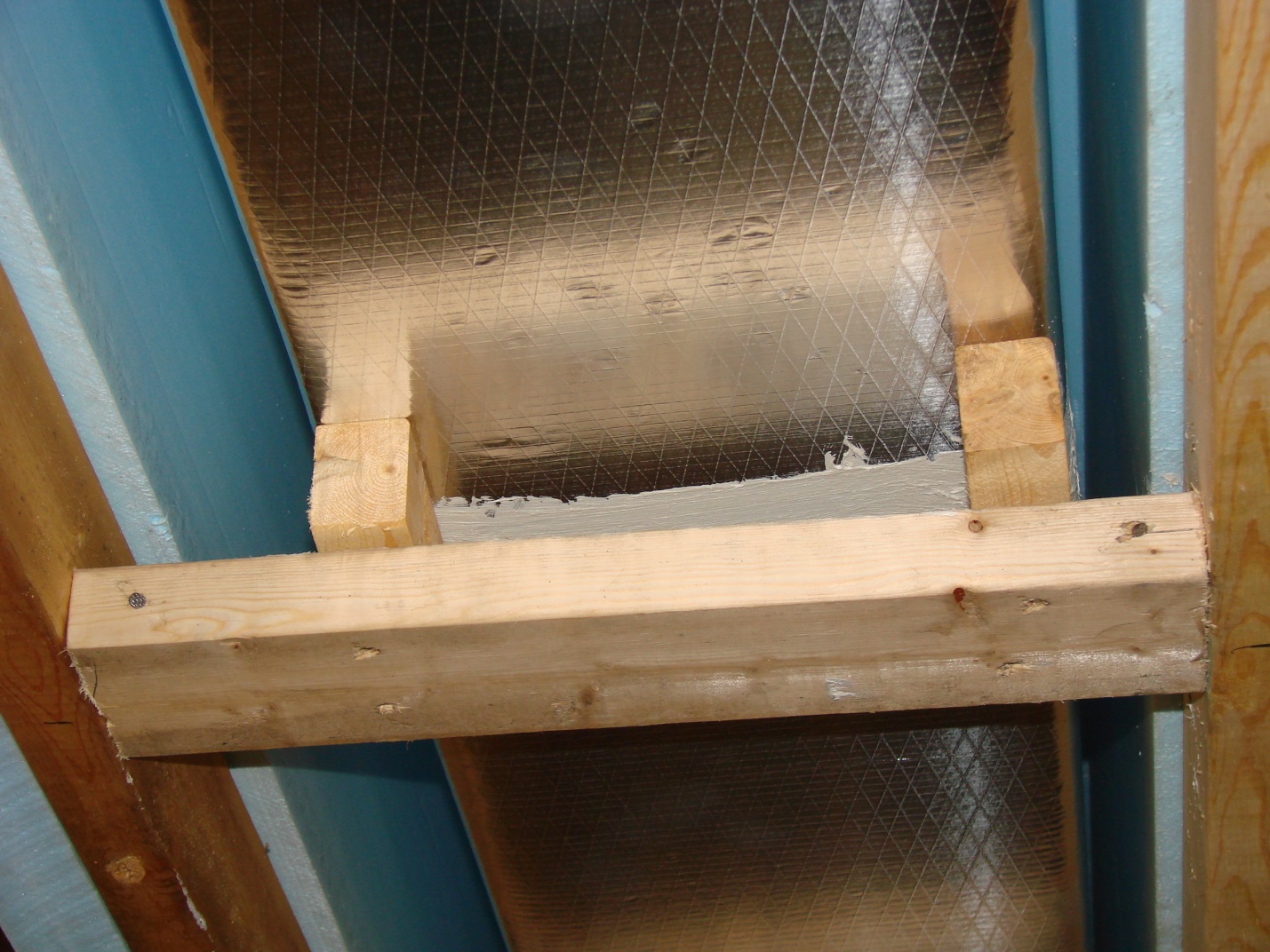
- Support the duct system. To hold the duct inside the chase, supports are screwed into the 2x4 ledge in-line with the trusses to facilitate the installation of the ceiling drywall. The bottom of these supports is also located ½ inch above the bottom chord of the trusses to facilitate the later installation of a ½ inch rigid chase bottom.
- Install run-out ducts to supply air to rooms off the main hallway.
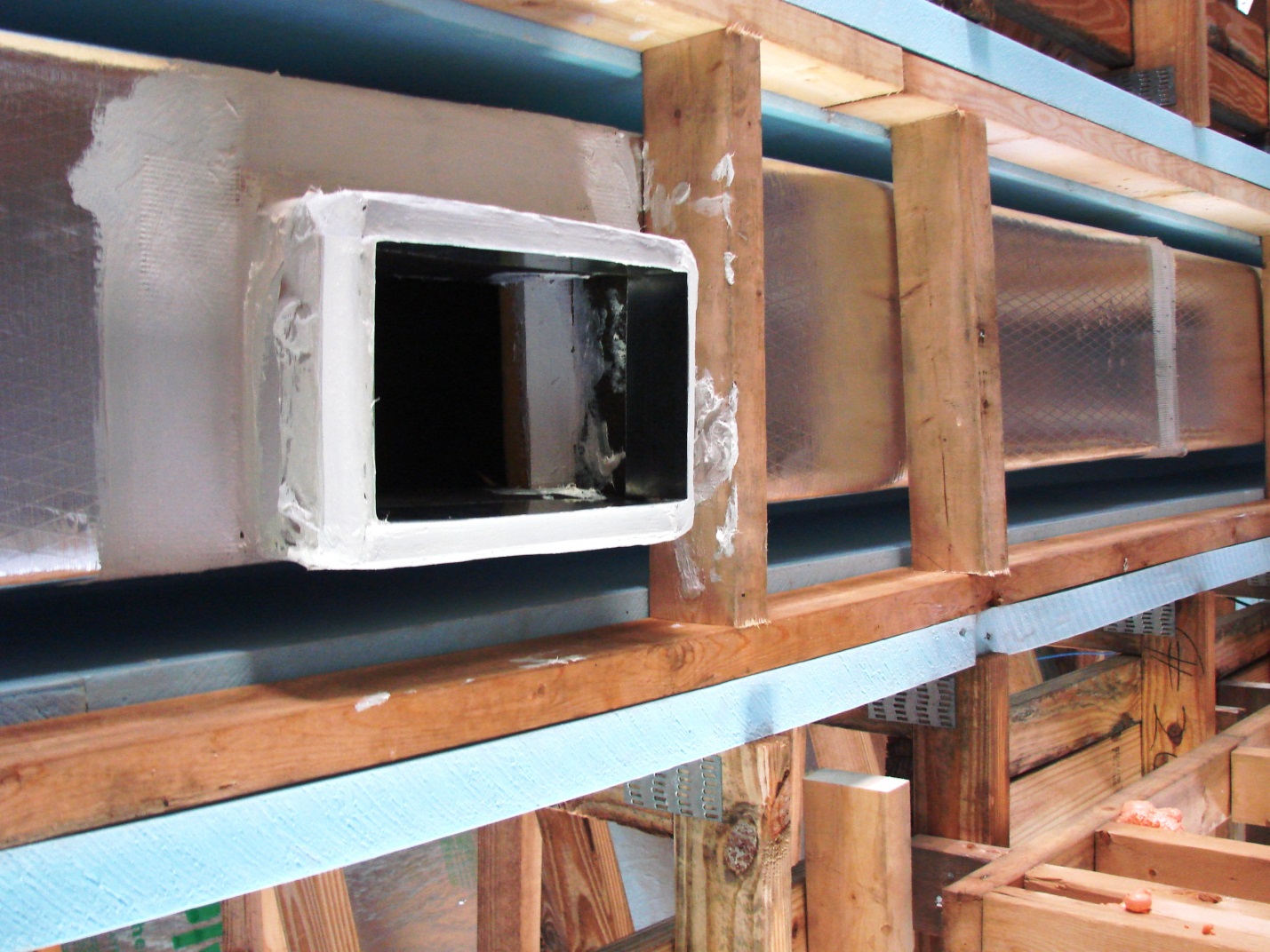
- Seal run-out ducts and support them. After the duct is supported in the chase, run out ducts are installed to extend to rooms off the chase path. These run-outs need to be supported and well-sealed to the main duct trunk. In this installation, pan stock was used to form boots for register installation.
- Install pan stock and seal to the chase to make boots for register installation.
- Prepare to seal the bottom of the chase with ½ inch rigid insulation. The run-out ducts and register drops are sealed with mastic, and boots are formed with pan stock and sealed. Adhesive is installed at the bottom of the chase sides to attach the rigid insulation to the bottom of the chase.

- Seal the bottom of the chase with rigid insulation. For this installation, the partner decided to seal the bottom of the chase with a layer of ½ inch rigid insulation attached with foam adhesive, then sealed with foil tape, and nailed to the previously installed duct supports.

- Finish sealing the bottom layer of rigid insulation. After the bottom rigid insulation is installed, the seams are further sealed with foil tape. For more security, the bottom layer of rigid insulation is nailed to the duct supports and the ledge running along the sides of the chase.
- Install a layer of batt insulation to the top and sides of the chase. As a last step, to bring the chase’s R-value in line with the rest of the attic, the top and sides of the chase are wrapped with R-13 batt insulation.
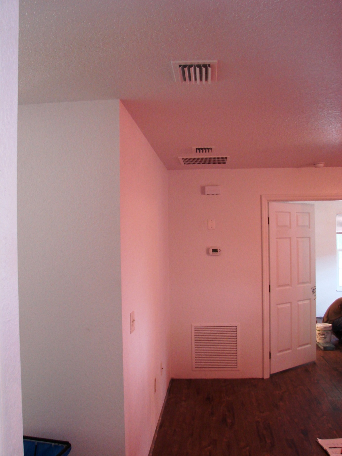
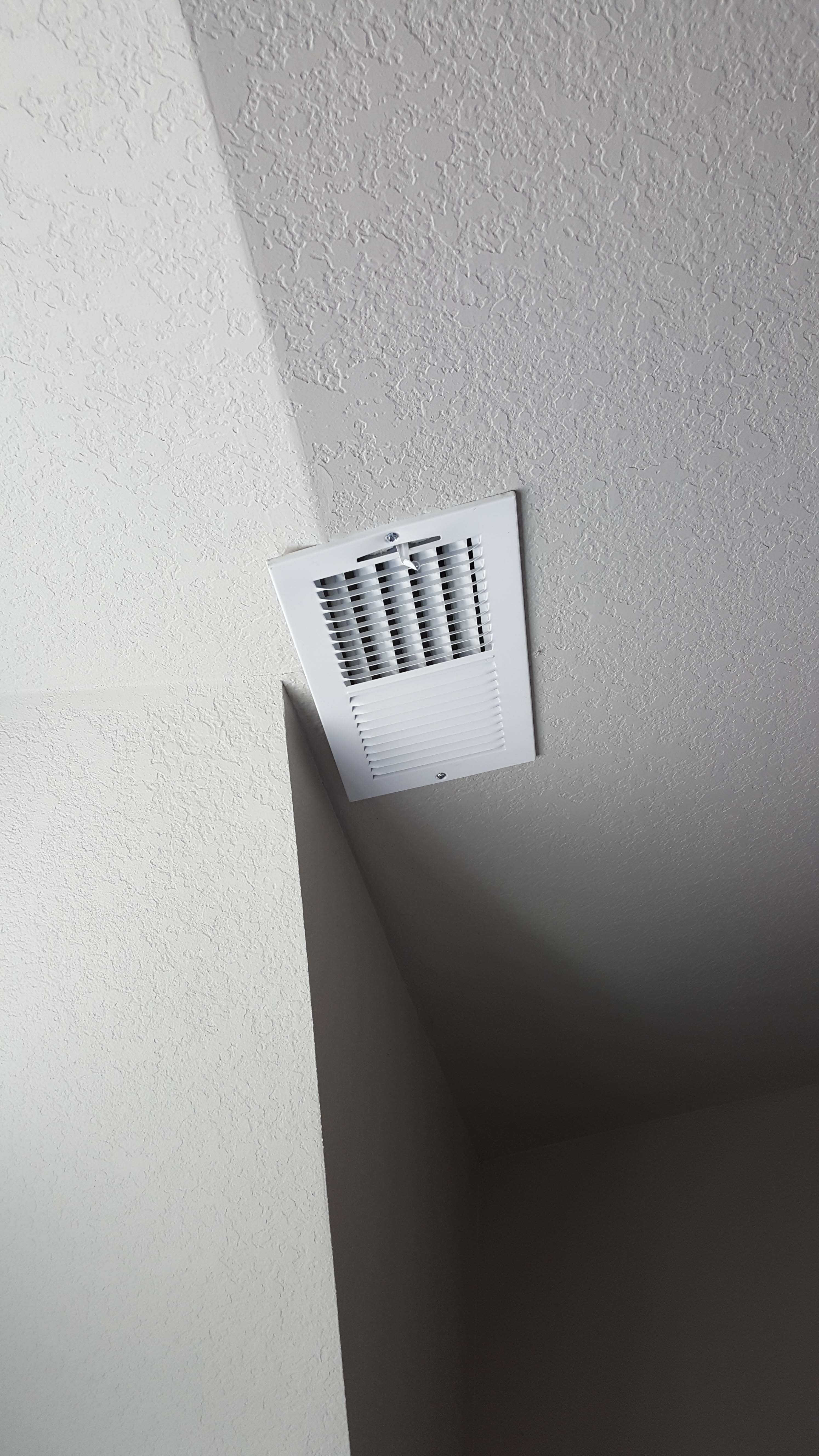
- The finished chase remains undetectable from the interior of the house.
19. As an alternative, the chase’s sides, top, and bottom can be constructed from drywall. The seams are sealed with drywall mud (Figure 18).
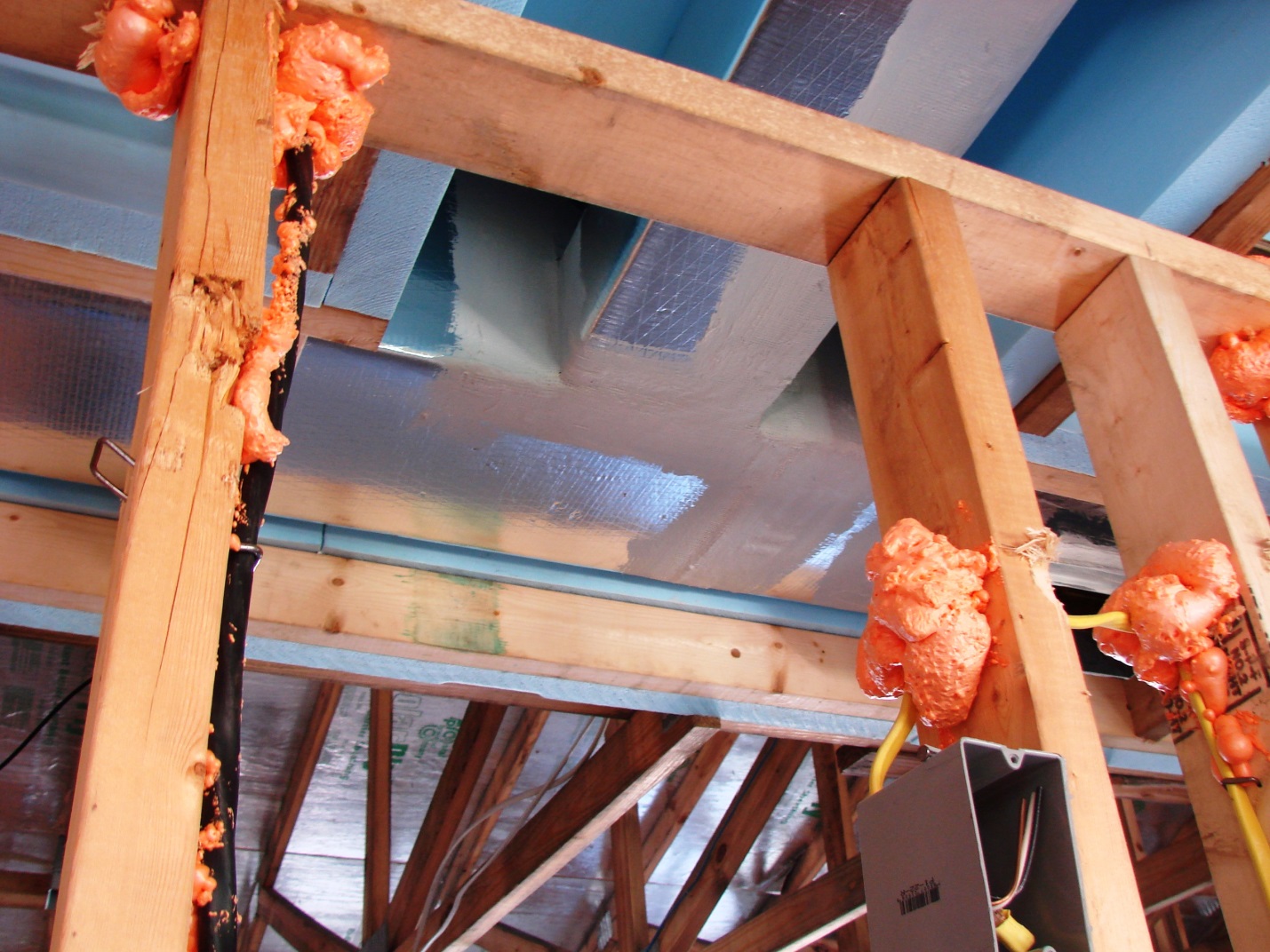
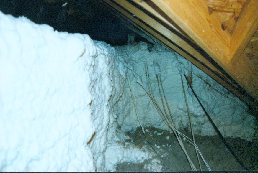
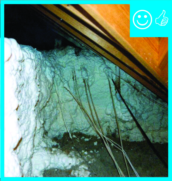
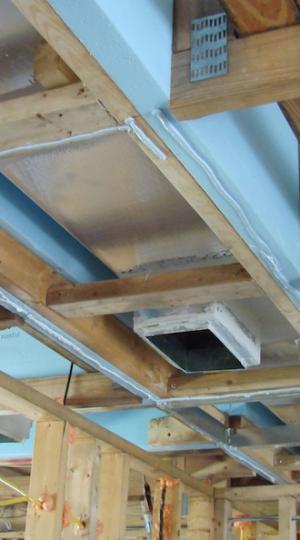
After the chase is built and air sealed, it needs to be insulated. If the chase is in an unconditioned attic, it should be insulated to a level similar to the attic itself. Spray foam (Figure 19) and batt insulation are good options.
Ensuring Success
The builder must make a clear and consistent commitment to building an interior duct system. Then this commitment must be communicated to all of the relevant trades. All involved parties (trades, designers, architects, etc.) must be dedicated to this task.
A raised ceiling interior duct system requires trade coordination, which is best accomplished by a site meeting after house dry-in. This meeting should include the designer; sales/marketing professionals; and mechanical, insulation, plumbing, electrical, framing, sheet rockers, and solar contractors.
Oversight duties are increased for the site supervisor. Diligent inspection and constant oversight by an informed site supervisor are necessary to ensure that all trades people involved with the process are aware of the chase and its function. The site supervisor must be aware that even if the subcontractors and employees are informed about the chase and its function, the actual workers on the job site may be unaware of this component.
Even after the house is completed, the chase area is subject to damage when the new homeowners have alarm, cable, and telephone services installed. Therefore, homeowner awareness of the chase’s function is another important part of successfully implementing a raised ceiling chase.
Verification
Blower Door Testing
During blower door testing, the pressure in the chase can be checked with respect to the house. If there is no pressure difference between the house and chase, the chase area is truly interior. In other words, it is completely inside the air boundary of the house. Depending on the pressure variation between chase and interior, a determination can be made regarding the integrity of the interior duct system.
Duct Blaster Testing
Two tests can be performed with the duct blaster, one that measures the leakage of the entire duct system - both into the interior and exterior of the house, and a second test that measures the duct leakage to the exterior of the building only. The results of the second test, leakage to the outside, are important regardless of duct style; leakage to the outside is energy lost. Obviously, any significant leakage results here indicate that the duct system is connected to the outside in some fashion, indicating a breakdown in the air barrier in the chase or in the sealed attic or crawlspace.
See the guides Duct Leakage to Outdoors and Total Duct Leakage Tests for more information.
Region
No climate-specific information applies.
Training
Right and Wrong Images
Source
Document illustrating guidelines for efficient installation of interior duct systems in new housing.
Source
Source
Source
Source
Compliance
Retrofit
SCOPE
Construct a sealed, insulated chase over ducts installed on the floor of a vented attic in an existing home to bring the duct work into the conditioned space of the home.
- Conduct a pre-retrofit analysis to determine if this complex retrofit technique is the most feasible, cost-effective method to use to accomplish the project goals (decreased energy consumption, improved HVAC performance, etc.).
- Conduct the following pre-retrofit assessments to determine existing conditions:
- Pre-Retrofit Assessment of Attics, Ceilings, and Roofs
- Pre-Retrofit Assessment of Existing HVAC Systems
- Pre-retrofit Assessment for Combustion Safety (especially if the home contains an atmospherically vented combustion furnace or water heater).
If proceeding with this technique:
- Collect as-built drawings of the attic.
- Prepare a scope of work for each contractor.
- Relocate the air handler in the home’s interior or create a sealed closet connected to the home’s conditioned space around any air handling equipment installed in the garage, attic, or other unconditioned space.
- Construct the chase around the new or existing attic duct work that is adjacent to the ceiling; seal the chase to the ceiling plane; seal all seams in the chase.
- Insulate the top and sides of the chase to an R-value equal to or exceeding the existing attic insulation or applicable code requirements.
Before committing to the raised-ceiling section retrofit strategy, compare the cost, benefits, and practicality to these alternative approaches:
- Alternative 1: Air seal and insulate the existing duct system or replace the existing ducts with a new, compact, air-tight, well-insulated duct system that is in the same location as the existing duct system. This does not bring the ducts into conditioned space, but it produces some of the same results. OR
- Alternative 2: Replace the existing duct system with a well-constructed, tight, and well insulated duct system installed inside the home, for example in a new fur-down or dropped chase below the existing ceiling. OR
- Alternative 3: Retain the existing duct system and air handler in place and turn the existing attic into a sealed, insulated attic space by closing off vents and insulating along the underside of the roof line. OR
- Alternative 4: Encapsulate the new or existing duct work in spray foam and “bury” it in additional blown insulation.
- Alternative 5: Replace the ducted equipment with non-ducted equipment installed in the home.
For more on duct sealing and insulating, see the U.S. Department of Energy’s Standard Work Specifications. The Specifications also discuss safe work practices.
DESCRIPTION
The raised ceiling approach described for new construction (in the Description tab) uses specially designed roof trusses. This approach is obviously not feasible in retrofit situations (unless a complete replacement of roof and trusses is already part of the remodel).
In a retrofit situation, a chase is constructed over the ducts, which are lying on the existing ceiling. The chase is sealed to the existing ceiling and covered with insulation, creating a sealed, insulated space around the duct. New openings in the existing ceiling will connect the interior of the duct chase to the conditioned space below so the duct chase is thermally connected to the house below. Because this in essence extends the ceiling up and over the duct system, this technique is referred to as a raised ceiling or fur-up chase.
The duct chase formed by the new raised ceiling section improves duct performance in two ways. First, any air leakage from the ducts will only involve an exchange of conditioned air. Second, the duct work will be isolated from the extreme temperatures in the vented attic, reducing heat gains and losses.
This retrofit technique is only feasible if the duct layout is compact with short branches off a main trunk and if there is enough attic space around the main duct to construct the chase. Attempting to retrofit ducts by conducting a chase over the ducts is challenging in the best of circumstances and often will not be cost effective. Trusses, low-pitched roof lines, and other structural components all limit access, making this technique more complicated and decreasing the likelihood of success.
Conduct the pre-retrofit assessments described in Step 1 below to assess existing conditions and to determine if the home is a good candidate for this retrofit strategy.
Alternatives to a Raised Ceiling Chase
Consider other retrofit options that can improve the performance of existing ducts. Work with contractors to estimate the first-cost of installing a raised ceiling chase versus the costs for the alternatives listed here. Work with a RESNET certified home energy rater to evaluate the energy benefits of the raised ceiling approach versus the following alternatives:
- Alternative 1: Air seal and insulate the existing duct system or replace it with a new well-constructed, airtight, and well-insulated system also installed in the vented attic. Part of the benefit of bringing the duct system into the conditioned space is reducing duct leakage to unconditioned space. Installing a new duct system that is well sealed, or sealing the existing ducts if they are in good condition, may achieve a large portion of that improvement. Sealing the existing ducts or installing new sealed ducts should be part of implementing a raised ceiling section approach anyway. This step alone may produce the bulk of projected energy savings and it entails a much simpler scope of work. Combine this with air handler closet improvements. In BASC, see
- Alternative 2: Replace the existing attic-mounted duct system with a well-constructed, airtight, and well-insulated system that is installed inside the home, for example in a fur-down chase. In this approach, the existing duct system in the attic is abandoned and a new duct system is installed below the existing ceiling. It may actually be much less expensive to install new ducts inside the home’s building envelope rather than trying to enclose ducts located in the attic. The duct path throughout the house is created with fur-down chases in hallways and closets, soffits over cabinets, and architectural details. Careful air sealing of any opening made through an interior wall is required to avoid creating an air flow path from the attic down through the wall cavity. The new fur-down chases need to be integrated with a retrofit of an existing or new air handler closet, also in the conditioned space. Those costs aside, it is likely comparable to the cost of the raised ceiling approach, but the generous work space below the ceiling may make it easier. (In BASC see Ducts in Dropped Ceilings.)
- Alternative 3: Insulate the attic with spray foam. You can turn the entire attic into a sealed, insulated semi-conditioned attic space for the ducts by spraying the underside of the roof deck, all vertical surfaces (such gable walls), soffits, and eaves with spray foam to form a continuous air-tight and insulating barrier around the attic. The foam is typically a two-component spray foam that is mixed on site by a foam insulation contractor. Closed-cell and open-cell foams are available. Closed-cell foam offers a higher R-value per inch of thickness, but it is often more expensive per square foot than open-cell foam. The achievable R-value is lower than other attic insulation options because the foam thickness is limited by the material’s physical properties. The approach is impractical for low-pitched roofs, particularly if the existing duct system obstructs access throughout the attic. While foam sealing the attic is likely to be more expensive than creating a raised ceiling duct chase, it can provide additional benefits such as reducing air infiltration into the attic or creating a quasi-conditioned space for storage. See BASC Below Deck Spray Foam Insulation for Existing Roofs.
- Alternative 4: Foam encapsulating and burying new or existing duct work. [This approach is not recommended for humid climates.] This approach provides the benefit of both reduced duct leakage and reduced heat exchange. The existing or new duct system is completely covered with spray foam. The ducts must be completely covered to ensure no attic air gets past the air and insulation barriers, which can lead to condensation on the cold duct surfaces. Limited work space and overhead clearance may limit access to all sides of the duct system, which is critical to the success of this strategy. See BASC: Encapsulated Ducts. See also BASC Ducts Buried in Attic Insulation and Encapsulated.
- Alternative 5: Replace the ducted equipment with non-ducted equipment installed in the home.
How to construct a duct chase over an existing or new duct system installed on the attic floor of an existing home.
Step 1: Conduct preliminary assessments.
Before beginning the retrofit design process for a raised ceiling duct chase, make sure the attic is a safe work space and determine if the HVAC system should be kept or replaced. If the air handler needs to be replaced, consider relocation options to make the raised ceiling retrofit easier and to make enclosing the air handler in the conditioned space. If major portions of the duct system need to be replaced, design the new duct system and the raised ceiling retrofit in tandem.
- Follow NREL Pre-Retrofit Assessment of Attics, Ceilings, and Roofs
- Follow NREL Pre-Retrofit Assessment of Existing HVAC Systems
- Follow Designing Forced-Air HVAC Systems guide
A successful implementation of the ductwork in raised ceiling sections will result in the ducts being very difficult to access. Therefore, the duct system should be in excellent condition and substantially air tight prior to enclosure. Work with a RESNET-certified home rater to assess the condition of the existing air distribution system and any new work at the time of installation, including the air handler, building cavities used as ducts (including unfinished wood frame return plenums), air handler closets, and mechanical rooms. Include sealing leaky ducts and eliminating unfinished building cavities used as ducts in the cost-benefit analysis of the raised ceiling approach.
- Follow NREL guides Duct Leakage to Outdoors and Total Duct Leakage Testing.
- Follow NREL guides “Duct Sealing” and “Air Handler Closet Retrofit.”
Step 2: Document existing conditions and design the raised ceiling chase.
Building a fur-up or raised-ceiling duct chase in an existing home requires careful planning. All installation and sealing details need to be developed in advance. Every portion of the new chase must be planned to prevent a mismatch between the duct size and the available space in the chase. Solicit design input from the HVAC contractor; contractors that will install, seal, and insulate the new raised ceiling chase; any other contractors involved in the project, and the local building code official.
Produce as-built drawings and drawings of raised ceiling chase path, materials, and assembly details. As part of the design process, document existing vertical chases and stacks in the attic, attic access points, structural members, and existing duct work with photos and sketches. Document existing exhaust fans and recessed lighting fixtures. Measure the horizontal and vertical clearances between trusses and joists along the anticipated path of the chase.
Using the as-built sketches, layout the path of the new raised ceiling duct chase around immovable elements of the attic. If any vertical shafts will be included in the design, refer to sealing details in “Air Sealing Duct and Flue Shafts.”
Plan for the relocation of exhaust fans and recessed lighting fixtures that interfere with the path of the chase.
The existing drywall that forms the ceiling of the conditioned space will become the floor of the new raised ceiling duct chase. Document and design details for the chase floor where the ceiling plane is irregular (e.g., soffits over cabinets open to the attic).
For new ducts, develop duct sizing to fit within the finished interior dimensions of the chase to avoid compression and ensure adequate space is provided to make and seal connections between main trunks, supply run outs, and boots. For existing ducts not being replaced, develop a chase design to accommodate all vertical clearances.
Design passive air flow pathways from the duct chase into the house to ensure that incidental supply duct leakage will flow into the house rather than into the surrounding attic. The best way to do that is to make the chase very well connected to the conditioned space with a passive air flow pathway such as inoperable return grilles installed in the bottom of the chase or jump ducts from the chase to the ceiling of the conditioned space. This is the same as passive return air pathways between bedrooms and the main areas of homes that have central return plenums. In BASC see “Jump Ducts.” If sections of the duct chase will be isolated from each other, plan for a passive air flow pathway into the conditioned space in each section. If the ducts will fit very tight in the chase or airflow within the chase will be limited by structure, install multiple grilles to allow communication with conditioned space all along the chase. Ensure that the duct work itself does not cover the passive air flow pathways.
The limited access within most attics requires careful planning for the size, staging, and installation of all materials. Ensure that, as the chase is constructed, it will not block access to portions of the chase deeper in the attic. Mock up a section of the chase to make sure the intended attachment and sealing methods can be executed in the available space. During design, visit the attic with various size samples of the intended air barrier material to test maneuverability within the attic space.
Based on the duct leakage testing, plan for any repair and sealing work that needs to be done. Consult with the contractor who will do the work on whether it should be done before or during the raised ceiling chase construction.
To reap the full benefit of creating an interior duct system, the air handling equipment should be brought into the conditioned space as well. Develop details for relocating air handling equipment or constructing a sealed and insulated closet around the existing equipment. Read through the construction steps below to get a better understanding of the many design details that need to be addressed.
Prior to finalizing the design, review the plans with the local building code. Make changes as needed to conform with local codes and best practices.
Determine the insulation method for the chase sides and top. The sides of the chase are, in essence, attic knee walls. In BASC, see “Attic Knee Walls.” Insulation choice should be considered in the design of the chase structure. Consider the depth needed and attachment method for the insulation. The addition of structural elements to support insulation has not been addressed in this guide because of the wide variation in desired R-values and diversity of insulation materials available.
Step 3: Bring the air handler into conditioned space.
If the air handler unit is located in unconditioned space it should also be brought into conditioned space, in one of the following ways:
- Relocate air handling equipment (must be planned for during design); OR
- Retrofit an unfinished closet in conditioned space with an air barrier; OR
- Construct a closet around an air handler located in the garage or attic.
If air handlers are located in an interior closet, the closet should be finished with mudded and taped drywall. The return plenum should be ducted from the return grille to the return side of the air handler. See the BASC guide “Air Handler Closet Retrofit.”
To construct a sealed closet around the air handling equipment already located in the garage or attic, see the guide “No Ducts or Air Handlers Located in Garage” by IBACOS. Ideally, air handlers and ducts should not be located in the garage. Don’t move the air handler into the garage as part of the retrofit. If possible, move air handlers located in the garage into the conditioned space of the home as part of the retrofit. Do not locate duct supply or return registers in the garage. If the air handler must remain in the garage, construct an airtight closet around it. Install a self-closing door and weather-strip the door frame.
Connect the closet to the home’s conditioned space via a sealed transfer grill or jump duct to ensure any depressurization of the closet draws air from the house, not the adjacent unconditioned space. In BASC see “Jump Ducts.”
All return or supply plenums in the new equipment room or closet should be sealed in accordance with local codes. See “Duct Sealing,” “Sealed and Insulated Fiber Board Ducts,” “Sealed and Insulated Flex Ducts,” and “Sealed and Insulated Metal Ducts.”
Electric air handlers installed in garages or attics should also be encased in an air-sealed closet with a weather-stripped access door.
Step 4: Construct a chase around the new or existing duct work.
A sealed and insulated chase is built around the attic-mounted duct work. To reiterate, this is a challenging proposition in anything less than a gut-rehab project and may necessitate a duct system replacement. The existing ceiling will become the bottom of the new raised ceiling duct chase. New framing, thermal barrier, and air barrier materials will be installed to create the chase sides and top. New openings in the existing ceiling will connect the interior of the chase to the conditioned space. Conditioned air will move passively through the chase as it does through the rest of the conditioned space. Together, the sides and top of the chase constitute the new ceiling plane and thermal and air flow boundary between the attic and the conditioned space/air inside the chase. Therefore, it is just as important to air seal the chase as it would be to seal the ceiling plane in any home. Additionally, because the ducts will be inaccessible after the chase is completed, they should be sealed prior to installing the chase.
Caution: Any necessary duct sealing of existing ducts should be completed or planned for prior to starting construction of the raised ceiling chase. Once the chase is completed, the duct system will be inaccessible. The duct system should be well sealed with a code-approved, durable, long-life sealant at all seams, joints, and edges. In BASC see “Duct Sealing.”
Step 5: Lay out the chase and check the design on site in the attic prior to moving materials to the attic.
Mark where the sides and top of the chase will intersect existing framing members. Ensure that the chase does not cross over attic access hatches, attic stairs, or any unconditioned spaces such as garages and porches. Ensure that the chase will not be blocked by existing vertical plumbing. Ensure there is adequate room to install the chase sides and top around existing and/or new duct work. Never cut a structural member to accommodate a duct chase. Rearrange the exhaust fan and ventilation duct work to accommodate the duct chase without compromising fan flow.
Step 6: Prepare the floor of the chase.
Remove ceiling insulation where the chase will be installed. If any interior walls cross the path of the chase, seal the top plates of those walls and any plumbing or wiring penetrations through the top plates in the vicinity of the chase. Remove any recessed lighting fixtures in the chase path and patch and seal the ceiling.
Step 7: Install framing for the sides of the chase.
- Install nailers (i.e., framing) to form the top and bottom edge of each chase side. For faster assembly, first position nailers along the chase path.
- For sections of the chase running between roof trusses, attach nailers to the face of each truss at the designed chase side height and on the face of the bottom chord abutting the floor of the chase.
- Install vertical nailers between the top and bottom nailers every two feet to form a ladder type structure.
- Repeat the process for sections of the chase running perpendicular to the roof trusses. Before attaching these, double-check that the nailers are positioned within the same truss web.
- Install nailers through the webbing to create the same type of ladder structure. This structure must support not only the air barrier forming the chase sides and top, but also the chase insulation. If the design includes spray foam insulation applied to the outside of the chase, the structure must stand up to the force of the sprayer – not just support the weight of the finished spray foam.
- For attics without trusses, create chase sides using the same ladder method and attach to the ceiling joists.
- Use temporary bracing to stabilize the ladders. (Plan to leave enough bracing in place to prevent movement of the chase sides after completion.)
Caution: Temporary bracing may be installed across the span of the chase (i.e., between the two facing ladders) but attach it to the top of the nailers. Attaching it to the face of the nailers will interfere with construction of the continuous air barrier (next step). Permanent cross-bracing will be installed after the duct work has been completed.
Note for Steps 8 through 11: All mentions of sealing refers to the application of a code-approved, long-life material using a caulk gun for gaps equal to or less than ¼-in. If the gap exceeds ¼-in., first fill the gap with a small piece of the air barrier material or an appropriate thickness of backer rod, then follow up with a fiberglass mesh and mastic to seal over the whole gap.
Step 8: Install the air barrier for the chase sides.
If existing ducts are not being removed, work carefully in this step to avoid crushing, compressing, or disconnecting the ducts.
- Position the bottom edge of each piece of the air barrier so that it is touching or within ¼-in. from the ceiling.
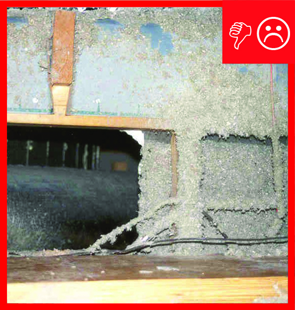
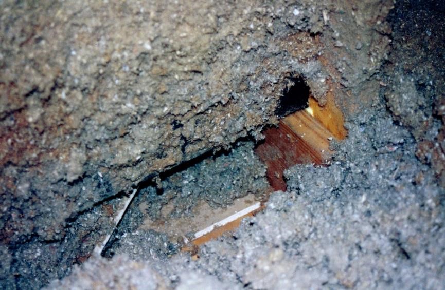
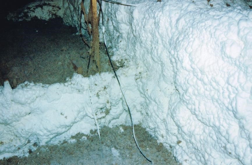
- For chases running perpendicular to trusses, it is difficult but critical to install the air barrier material such that it fills the gaps between the bottom chords; otherwise, the gaps will create a series of large holes in the chase side, connecting the chase interior to the attic (Figure 1). There are two approaches to filling these gaps:
- Cut a notch in the bottom edge of the air barrier to fit around the bottom chord of each truss.
- OR, Set the bottom of the air barrier on top of the bottom chords and fill the gap between the truss bottom chords with a separate piece of air barrier material.
- Notch the air barrier to accommodate existing and future wiring or plumbing, taking care not to nick existing wiring.
- Screw air barrier material to the ladder structures along the top and bottom edge every 16 to 24 inches, closer if necessary to ensure each piece is secured in three places. Screw each piece of air barrier at least once to each vertical piece of the ladder structure to prevent warping.
- Seal the air barrier’s bottom edge to the floor of the chase. Seal the seams between pieces of abutting air barrier. Seal gaps around wiring and plumbing. Fill the gap between the air barrier and the nailer at the top of the chase side. The air barrier should be continuous across the floor up to the top of the chase sides.
- If the design incorporates chases of different heights, take care to create this continuous air barrier detail at every change in height using vertical nailers where necessary. From the inside of the chase, you should be able to see that every edge and seam has been sealed.
Before moving to the next step, the project manager should conduct a thorough inspection while the contractor is still on-site to correct deficiencies. If the contractor is no longer on site during the inspection, mark points to be sealed with a brightly colored marker.
Caution: If the retrofit involves an atmospheric-vented combustion gas water heater or furnace located in an air handler closet or mechanical room (which serves as the combustion air zone (CAZ)), where the chase intersects the CAZ closet or mechanical room ensure that there is a sealed air barrier to prevent accidental air exchange between the chase and the CAZ. This will reduce the risk of accidentally depressurizing the closet when an exhaust fan or dryer is running elsewhere in the conditioned space. Upon completion of the chase and any sealing in the air handler closet or mechanical room, it is imperative to retest the CAZ under worst case conditions and make any corrections necessary to maintain combustion safety. In BASC see Combustion Appliance Zone (CAZ) Testing.
Step 9: Prepare and install the duct work.
- Conduct a second duct blower test. While a pre-construction duct test should be done to identify and plan for repair of major problems, a second test should be done in this step. Work around existing ducts may have compromised the integrity of duct connections. The test should be done in this step even if the ducts have already been repaired, and even if a visual inspection does not turn up any defects. Once the chase has been closed up, it will be virtually impossible to do any further sealing of the ducts without significant deconstruction.
- Repair any loose duct connections. Allow mastic to dry before retesting.
- Mark locations of any new ceiling-mounted passive return air grilles on the chase floor, cut openings, and install any necessary blocking or strapping to support grilles.
- If new ducts are being installed, mark supply register locations on the floor of the chase.
- Cut the floor of the chase and install the boots, junction boxes, and plenums.
- Build duct runs in place or in pieces on the ground. Prior to building duct runs on the ground, test that the length can be threaded through the attic structure.
- Install sections farthest from the attic access first.
- Attach ducts to boots and plenums and seal the joints properly. In BASC see See “Duct Sealing,” “Sealed and Insulated Fiber Board Ducts,” “Sealed and Insulated Flex Ducts,” and “Sealed and Insulated Metal Ducts.”
Step 10: Create the framing for the top of the chase.
Install horizontal nailers for the top spanning the chase at intervals of 16 or 24 inches. Attach nailers to the INSIDE surface of the opposing side. The nailers should be positioned BETWEEN the chase sides, not on top of the chase sides. The top surface of the nailer MUST be flush with the top of the sides. Remove temporary bracing.
Step 11: Create an air barrier for the top of the chase.
It is unlikely that air barrier pieces longer than four feet can be maneuvered through the attic. Use the factory width of the sheet goods for the length of the air barrier, being careful to cut straight lines to avoid poor fit on top of the chase sides and nailers.
- First lay a continuous bead of code-approved 30- year sealant or a long-life gasket (factory made or material meant to block air flow such as sill seal) along the top surface of the side (the top of the upper nailer).
- Staple all gasket material in place.
- When using caulk, apply just before a section of the air barrier is laid in place to avoid caulk drying out or getting smeared.
- Lay the chase top air barrier onto the caulk or gasket.
- Butt each piece up against the previously laid piece to minimize sealing efforts later.
- Fasten the air barrier in place with screws at intervals of 16 or 24 inches ensuring that each edge of air barrier is secured in at least three places and at least once to each nailer spanning the chase to prevent warping. Gaskets should be compressed as much as possible.
Step 12: Seal the top of the chase.
Setting the top of the chase in caulk or on a gasket creates the seal between the top of the chase and the sides of the chase along its whole length. Carefully inspect and seal all joints between abutting pieces of the air barrier. Before moving to the next step, the project manager should conduct a thorough inspection. Although the chase is not to be used for forced air movement, only passive movement, it can be tested like a duct system by connecting the duct tester to one of the passive return air grilles. If the chase is slightly pressurized with the duct tester, workers will be able to feel air flow at any unsealed gaps in the chase sides and top that need further attention.
Step 13: Insulate the chase.
A raised ceiling duct is challenging to insulate. Gravity can pull batt insulation away from the sides of the chase.
- Install insulation to cover both the top and the sides of the chase. The R-value should be equivalent to adjacent attic insulation or should meet applicable code requirements. Even if the chase is being built with insulating board as the air barrier, it will likely need additional insulation applied to the attic side of the assembly to meet desired R levels.
- If spray foam is used (Figure 2), install markers that extend away from the chase sides (like the ones used with blown-in insulation) to help insulators target the right thickness and to provide an inspection aid.
- If using fiberglass batts or other insulation methods, test during design.
- Replace any disturbed attic insulation on the attic floor.
ENSURING SUCCESS
For all strategies:
Success relies on moving the home’s thermal and air barriers to bring the duct system from outside to inside the thermal and air barriers. Develop a clear plan for sealing the edges, joints, and seams of the new air barrier. These details are easy to overlook but are the single most important aspect of the retrofit. Create a checklist of sealing points for contractors to follow during construction prior to the project manager’s inspection. Work with the construction crew to ensure the plan is executed right from the start by establishing inspection points for each step of the process.
Do not install the top of the chase until:
- the duct system has been tested by a RESNET certified home energy rater and found or repaired to be substantially leak free (Qn, total ≤ 0.06)
- an inspection of the air barrier ceiling is completed and deficiencies are corrected.
Work with a RESNET certified home energy rater before, during, and after the retrofit to ensure the house is returned to similar or better operating characteristics after the retrofit. If the duct system is successfully brought into the home’s conditioned space, infiltration and exfiltration patterns of the house can change. This can result in unintended introduction of cold and dry or hot and humid outside air that can cause comfort complaints, drafts, and damage.
Do not operate atmospherically vented gas furnaces or water heaters, whether inside or outside the conditioned space, during the raised ceiling chase retrofit. A combustion air zone (CAZ) pressure test should be carried out at any time during retrofit work that the house will resume normal occupancy to ensure the operating parameters of the house have not been detrimentally changed by the raised ceiling duct system. This would include, for example, if part of the retrofit work is completed one week, then the house returns to normal occupancy for a week, and then the retrofit is completed the following week. It is imperative to maintain combustion safety during and after the retrofit to protect workers and occupants from potentially lethal back drafting of exhaust gases. In BASC see “Pre-retrofit Assessment Guide for Combustion Safety”
Determine the attachment method of the insulation for the sides and top of the new chase in advance. Seek input from the insulation contractor and request that s/he prototype any methods that do not follow conventional construction practices.
To reiterate, retrofitting a system involving a raised ceiling duct system is going to be expensive and difficult to do correctly. If the sole goal of the retrofit is to save money, it may be doomed to failure. After conducting the pre-retrofit assessments above, careful economic analysis of the costs of implementation versus the projected savings from bringing the duct into the interior should be carried out. Also consider the cost and benefit of simply replacing the existing duct system with a new, well-insulated and leak-free duct system in the same location, an easier and less expensive option which often generates a positive cash flow when installed in existing homes.
Worker safety is a concern with this retrofit. Workers must be constantly vigilant to avoid falling through the ceiling or hitting one’s head on rafters, trusses, or roofing nails. Review plans and procedures with all workers in advance and strictly observe safety precautions. Plan for worker navigation through the attic and screw boards in place for walking surfaces where needed. Encourage workers to voice safety concerns and resolve issues prior to continuing work.
If new duct work is being installed, wait until the chase sides are completed, including air sealing, prior to installing the duct boots. If installed earlier, supports such as strapping for duct boots will create obstacles that the side air barrier will need to be fitted around.
Lay out the materials for the chase sides before beginning to attach them. If errors are found with the path, corrections can be made more easily prior to attachment.
Always apply sealant to the seams and edges of the chase air barrier from inside the chase (from above).
COMPLIANCE
In BASC: Code Compliance Brief: Sealing and Insulating Existing Vented Attics.
In BASC: Controlling Moisture in Unvented Attics - Code Compliance Brief
In BASC: Buried Ducts within Ceiling Insulation of Vented Attics in all Climate Zones - Code Compliance Brief - Code Compliance Brief
See Compliance tab.
More Info
Case Studies
References and Resources
*For non-dated media, such as websites, the date listed is the date accessed.
Contributors to this Guide
The following authors and organizations contributed to the content in this Guide.
Florida Solar Energy Center, lead for the Building America Partnership for Improved Residential Construction (BA-PIRC), a DOE Building America Research Team
David Beal, Janet McIlvaine, Florida Solar Energy Center
Sales
HVAC Ducts in Raised Ceiling Sections
Technical Description
Comfort systems work much better when they are located in the conditioned space of the home rather than in an unconditioned attic or crawl space. Raised ceilings are one option for integrating heating and cooling ducts inside a conditioned space. This entails building an airtight chase that extends up into the attic framing or trusses.
Questions? Comments? Contact our webmaster.