
Encapsulated Ducts

    Scope
    Scope Images
    Image
    Encapsulated ducts are sprayed with ccSPF in an unconditioned attic
    Scope

    When HVAC ducts are installed in a vented attic in any climate, encapsulate the ducts in closed-cell spray polyurethane foam (ccSPF) to protect them from temperature extremes in the unconditioned attic space.

    • Where possible, install ductwork so that it is in direct contact with (i.e., laying on) the ceiling and/or truss lower cords. Where all or some portion of the ducts cannot be laid on the attic floor (due to truss design or some other obstacle), then hang the ducts using straps or saddles to properly support the ducts.
    • Mechanically fasten and mastic-seal all duct connections.
    • Test total duct leakage. Add additional sealant if necessary.
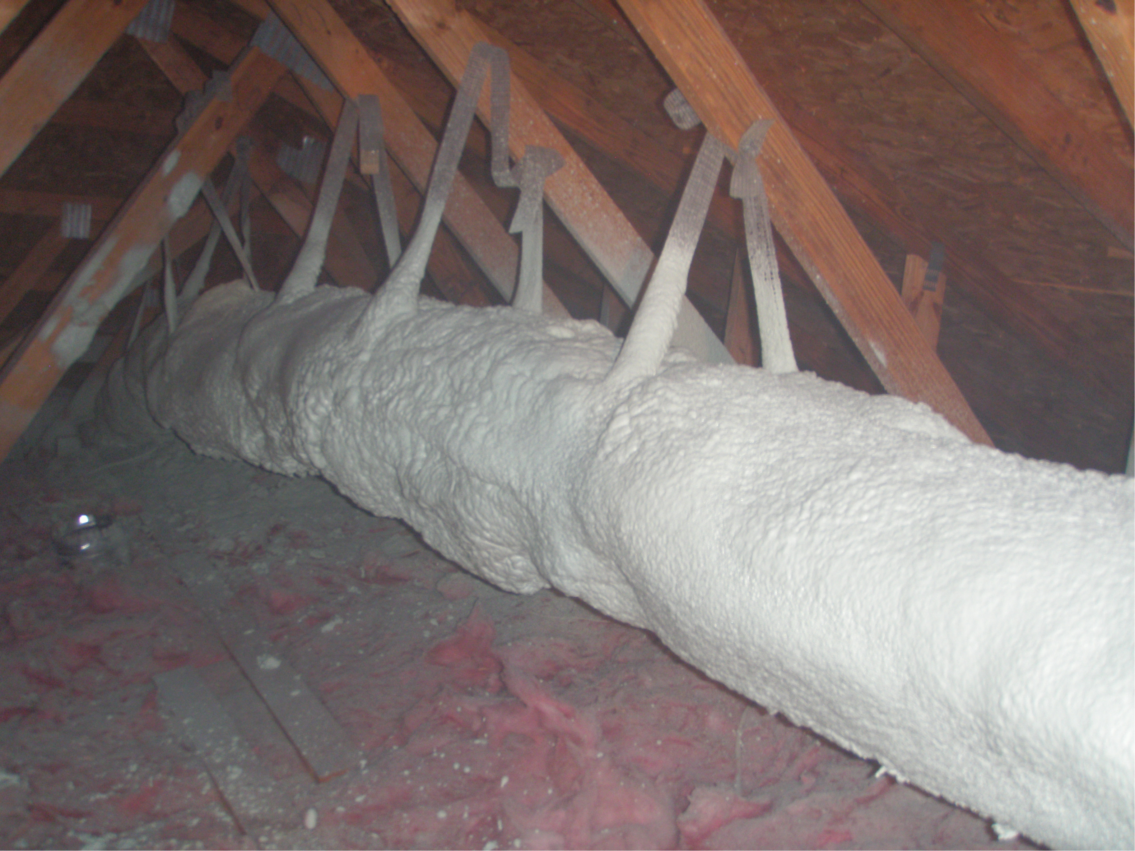
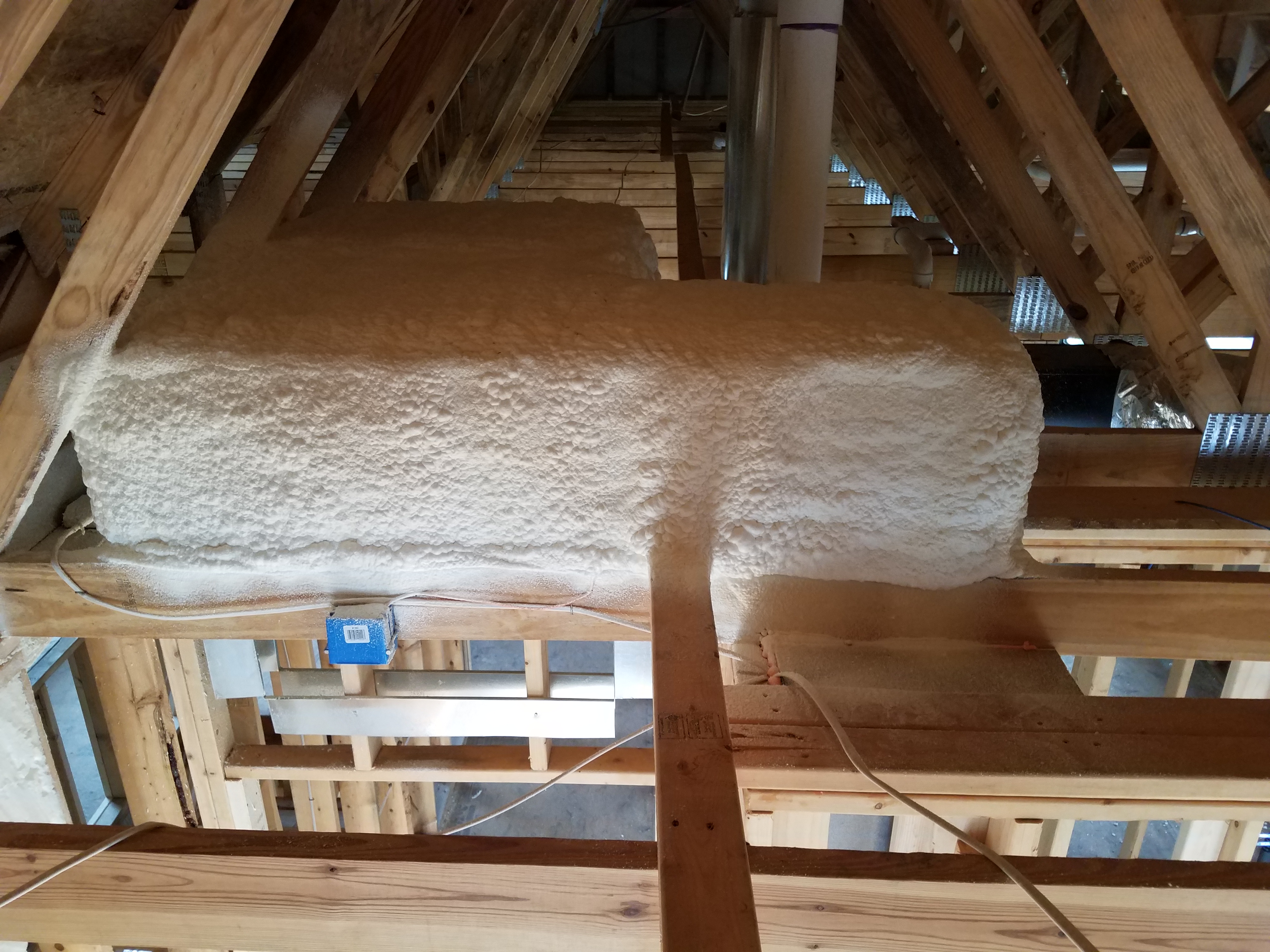
    • Completely encase the ducts in closed-cell spray polyurethane foam (ccSPF) to the desired foam depth.
    • This technique is appropriate for all climates including the humid or marine climates. 
    • This technique fulfills the DOE Zero Energy Ready Home program requirement that ducts be installed in conditioned space.

    See the Compliance Tab for related codes and standards requirements, and criteria to meet national programs such as DOE’s Zero Energy Ready Home programENERGY STAR Single-Family New Homes, and Indoor airPLUS.

    Description
    Description

    For homes with ducted heating and cooling systems, the best place to locate the duct system from an HVAC performance standpoint is within the conditioned space of the home, either in dropped ceilings, or between floors, or in a sealed and insulated basement, crawlspace, or attic. If the ducts must be located within a vented attic, one option for protecting the ducts and helping to minimize heat transfer between ducts and the unconditioned attic is to bury the ducts in the attic floor insulation. Where all or some portion of the ducts cannot be laid on the attic floor (due to truss design or some other obstacle), then the ducts can be hung or supported above the attic floor and encapsulated in closed-cell spray polyurethane foam insulation.

     Metal, flex, or fiber board ducts can be used. The ducts should be covered with R-8 or higher duct insulation and the duct insulation should include a vapor barrier cover. All duct connections should be mechanically fastened and mastic-sealed. The ducts should be tested for total duct leakage and any leaks should be sealed. The ducts should be hung using straps or saddles to properly support the ducts. See the guide Support at Intervals for Flex Ducts for more on properly supporting ducts. Once these preparations are made, the ducts can be encapsulated in at least 1.5 inches of closed-cell polyurethane spray foam. Encapsulating the ducts in spray foam increases the R-value of the ductwork and reduces air leakage. The effective R-value of an encapsulated duct installation depends on the size of the ducts, the level of the duct insulation, and the thickness of the ccSPF insulation. For example, the effective R-value of an 8-inch round duct encapsulated with 1.5 inches of ccSPF is R-12.7.

    How to Install Encapsulated Ducts

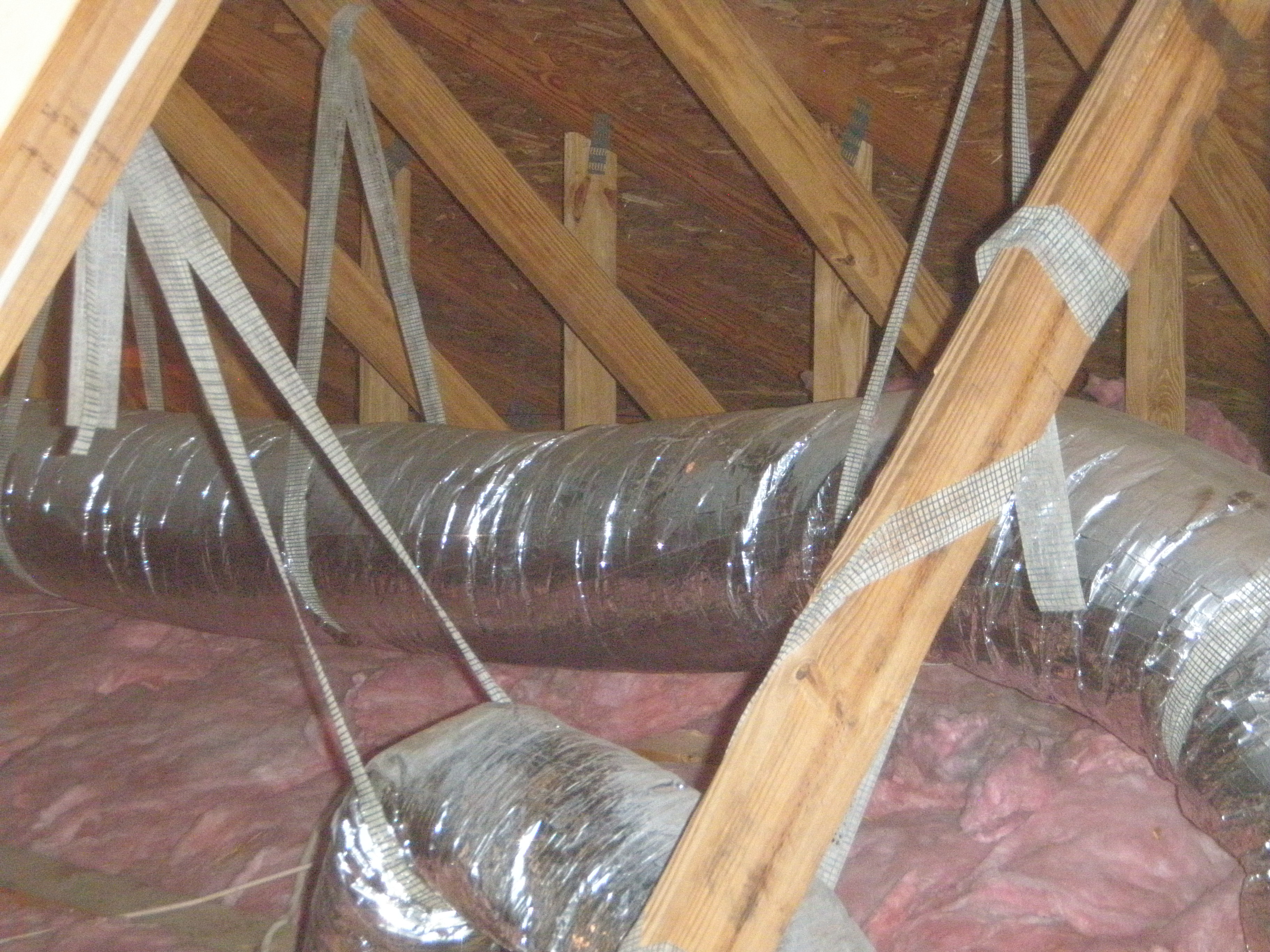
    1. Install ductwork with a minimum of R-8 duct insulation in accordance with low-profile duct design (Figure 1).
      This duct is insulated with a minimum of R-8 insulation.
      Figure 1. This duct is insulated with a minimum of R-8 insulation. (Source: Steven Winter Associates 2013.)
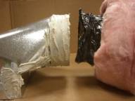
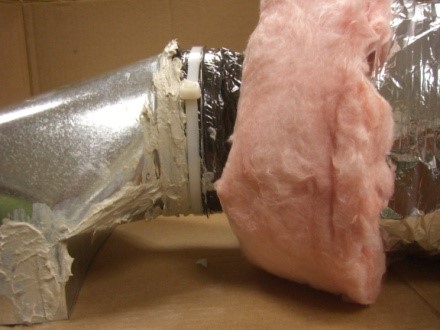
    2. Properly fasten and seal ducts at all connections. To attach flex duct, pull back outer liner, fasten inner liner over collar with tool-tightened tension tie, mastic seal the connection. Pull insulation and outer liner over the joint and seal to attached duct or boot with mastic or foil tape (Figure 2). The outer liner should not be attached with a tie as shown here but should be connected with mastic or foil tape to avoid compressing the insulation.Connection mastic-sealed.
      Connection mastic-sealed.
      Figure 2. The inner liner of the flex duct is fastened to the collar with a tension tie, the connection is sealed with mastic, then the outer layer is pulled over and sealed with mastic or foil tape. (Source: Steven Winter Associates.)
    3. Test total duct leakage to ensure that the ducts have been adequately sealed (total duct leakage < 3 cfm25 per 100 ft2 of conditioned space, Figure 3). Testing should be performed before encapsulation because it may be difficult to correct sealing issues after the application of spray foam.
      Total duct leakage testing.
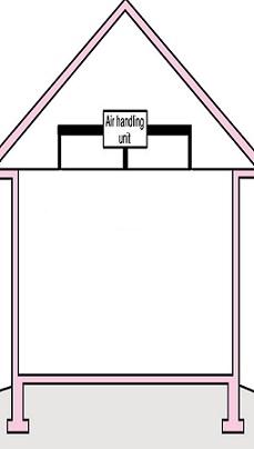
      Figure 3. A duct blaster is used to test total duct leakage. (Source: Steven Winter Associates 2013.)
    4. Apply at least 1.5 inches of ccSPF to all duct surfaces, including trunks, branches, and register boots. Ducts should be entirely encapsulated (see the Scope image).


    Success
    Ensuring Success

    To minimize air leaks and maximize effective R-values, ccSPF must be applied to all surfaces to the ductwork. All duct connections should be mastic sealed and ducts should be tested for leakage with a duct blaster before the ccSPF is applied.

    The 2009 IRC allows exposed installations of ccSPF in attics, but the spray foam must be specifically approved for installation without an ignition barrier.

    Climate
    Climate

    Encapsulated ducts may be installed in all climate zones, including moist (A) and marine (C) climate zones.

    The map in Figure 1 shows the climate zones for states that have adopted energy codes equivalent to the International Energy Conservation Code (IECC) 2009, 12, 15, and 18. The map in Figure 2 shows the climate zones for states that have adopted energy codes equivalent to the IECC 2021. Climate zone-specific requirements specified in the IECC are shown in the Compliance Tab of this guide. 

    Climate Zone Map from IECC 2009, 12, 15, and 18.
    Figure 1. Climate Zone Map from IECC 2009, 12, 15, and 18. (Source: 2012 IECC)


    Climate Zone Map from IECC 2021.
    Figure 2. Climate Zone Map from IECC 2021. (Source: 2021 IECC)


    Training
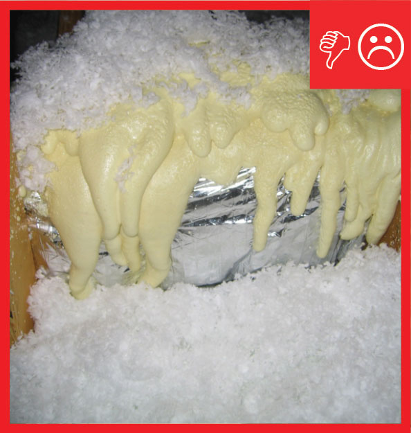
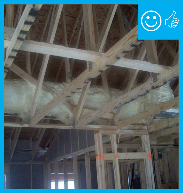
    Right and Wrong Images
    Image
    Wrong: Ductwork is not fully encapsulated with ccSPF insulation. The duct jacket is still fully visible at sections of the duct
    Wrong: Ductwork is not fully encapsulated with ccSPF insulation. The duct jacket is still fully visible at sections of the duct
    Image
    Right: ductwork is fully encapsulated with ccSPF prior to ceiling installation and burial
    Right: ductwork is fully encapsulated with ccSPF prior to ceiling installation and burial
    Image
    Right – All supply ducts in this home were located in conditioned space; any return ducts that were located in the attic were insulated with closed-cell spray foam and buried in the blown-in attic insulation to prevent air leakage and heat loss.
    Right – All supply ducts in this home were located in conditioned space; any return ducts that were located in the attic were insulated with closed-cell spray foam and buried in the blown-in attic insulation to prevent air leakage and heat loss.
    Presentations
    Author(s)
    Zoeller
    Organization(s)
    Steven Winter Associates
    Description
    Presentation with technical training covering several possible approaches to locating ducts within the home’s air and thermal barriers, and then dig into design considerations and details for the spray foam encapsulation approach.
    Videos
    Compliance

    Compliance

    The Compliance tab contains both program and code information. Code language is excerpted and summarized below. For exact code language, refer to the applicable code, which may require purchase from the publisher. While we continually update our database, links may have changed since posting. Please contact our webmaster if you find broken links.


    ENERGY STAR Single-Family New Homes, Version 3/3.1 (Rev. 11)

    National Rater Field Checklist

    HVAC System.
    6. Duct Quality Installation - Applies to Heating, Cooling, Ventilation, Exhaust, & Pressure Balancing Ducts, Unless Noted in Footnote.
    6.3 All supply and return ducts in unconditioned space, including connections to trunk ducts, are insulated to ≥ R-6.38
    6.4 Rater-measured total duct leakage meets one of the following two options. Alternative in Footnote 40:39, 40, 41
    6.4.1 Rough-in: The greater of ≤ 4 CFM25 per 100 sq. ft. of CFA or ≤ 40 CFM25, with air handler & all ducts, building cavities used as ducts, & duct boots installed. All duct boots sealed to finished surface, Rater-verified at final.42
    6.4.2 Final: The greater of ≤ 8 CFM25 per 100 sq. ft. of CFA or ≤ 80 CFM25, with the air handler & all ducts, building cavities used as ducts, duct boots, & register grilles atop the finished surface (e.g., drywall, floor) installed.43
    6.5 Rater-measured duct leakage to outdoors the greater of ≤ 4 CFM25 per 100 sq. ft. of CFA or ≤ 40 CFM25.39, 44

    Footnote 38) Item 6.3 does not apply to ducts that are a part of local mechanical exhaust and exhaust-only dwelling unit mechanical ventilation systems. EPA recommends, but does not require, that all metal ductwork not encompassed by Section 6 (e.g., exhaust ducts, duct boots, ducts in conditioned space) also be insulated and that insulation be sealed to duct boots to prevent condensation.

    Footnote 39) Items 6.4 and 6.5 generally apply to the ducts of space heating, space cooling, and dwelling unit mechanical ventilation systems. However, visual inspection is permitted in lieu of testing for a dwelling unit mechanical ventilation system not connected to the space heating or space cooling system, regardless of the number of dwelling units it serves. In such cases, a Rater shall visually verify that all seams and connections are sealed with mastic or metal tape and all duct boots are sealed to floor, wall, or ceiling using caulk, foam, or mastic tape. For duct systems requiring testing, duct leakage shall be determined and documented by a Rater using ANSI / RESNET / ICC Std. 380 including all Addenda and Normative Appendices, with new versions and Addenda implemented according to the schedule defined by the HCO that the home is being certified under. Leakage limits shall be assessed on a per-system, rather than per-home, basis.

    Footnote 40) For a duct system with three or more returns, the total Rater-measured duct leakage is permitted to be the greater of ≤ 6 CFM25 per 100 sq. ft. of CFA or ≤ 60 CFM25 at ‘rough-in’ or the greater of ≤ 12 CFM25 per 100 sq. ft. of CFA or ≤ 120 CFM25 at ‘final’.

    Footnote 41) Note that compliance with Item 6.4.1 or 6.4.2 in conjunction with Section 4a of the National Rater Design Review Checklist automatically achieves Grade I total duct leakage per ANSI / RESNET / ACCA Std. 310.

    Footnote 42) Cabinets (e.g., kitchen, bath, multimedia) or ducts that connect duct boots to toe-kick registers are not required to be in place during the ‘rough-in’ test.

    Footnote 43) Registers atop carpets are permitted to be removed and the face of the duct boot temporarily sealed during testing. In such cases, the Rater shall visually verify that the boot has been durably sealed to the subfloor (e.g., using duct mastic or caulk) to prevent leakage during normal operation.

    Footnote 44) Testing of duct leakage to the outdoors can be waived in accordance with the 2nd or 3rd alternative of ANSI / RESNET / ICC Std. 301, Table 4.2.2 (1), footnote (w). Alternatively, testing of duct leakage to outdoors can be waived in accordance with Section 5.5.2 of ANSI / RESNET / ICC Std. 380 if total duct leakage, at rough-in or final, is ≤ 4 CFM25 per 100 sq. ft. of conditioned floor area or 40 CFM25, whichever is larger. Guidance to assist partners with these alternatives, including modeling inputs, is available at http://www.energystar.gov/newhomesguidance.

    Please see the ENERGY STAR Single-Family New Homes Implementation Timeline for the program version and revision currently applicable in your state.


    DOE Zero Energy Ready Home (Revision 07)

    Exhibit 1 Mandatory Requirements.
    Exhibit 1, Item 1) Certified under the ENERGY STAR Qualified Homes Program or the ENERGY STAR Multifamily New Construction Program.
    Exhibit 1, Item 3) Duct distribution systems located within the home’s thermal and air barrier boundary or an optimized location to achieve comparable performance.

    Footnote 14) Exceptions and alternative compliance paths to locating 100% of forced-air ducts in home’s thermal and air barrier boundary are:

    1. Up to 10’ of total duct length is permitted to be outside of the home’s thermal and air barrier boundary.
    2. Ducts are located in an unvented attic, regardless of whether this space is conditioned with a supply register.
    3. Ducts are located in a vented attic with all of the following characteristics: [​Note that in either of these designs the HVAC equipment must still be located within the home’s thermal and air barrier boundary.]
      1. In Moist climates (Zones 1A, 2A, 3A, 4A, 5A, 6A and 7A per 2015 IECC Figure R301.1) and Marine climates (all “C” Zones per 2015 IECC Figure R301.1), minimum R-8 duct insulation with an additional minimum 1.5” of closed-cell spray foam insulation encapsulating the ducts; duct leakage to outdoors ≤ 3 CFM25 per 100 ft2 of conditioned floor area (in addition to meeting total duct leakage requirements from Section 4.1 of the ENERGY STAR HVAC Rater checklist); and ductwork buried under at least 2” of blown-in insulation.
      2. In Dry climates (all “B” Zones per 2015 IECC Figure R301.1), minimum R-8 duct insulation; duct leakage to outdoors ≤ 3 CFM25 per 100 ft2 of conditioned floor area (in addition to meeting total duct leakage requirements from Section 4.1 of the ENERGY STAR HVAC Rater checklist); and ductwork buried under at least 3.5” of blown-in insulation.
    4. Systems which meet the criteria for “Ducts Located in Conditioned Space” as defined by the 2018 IECC Section R403.3.7
    5. Jump ducts which do not directly deliver conditioned air from the HVAC unit may be located in attics if all joints, including boot-to-drywall, are fully air sealed with mastic or foam, and the jump duct is fully buried under the attic insulation.
    6. Ducts are located within an unvented crawl space.
    7. Ducts are located in a basement which is within the home’s thermal boundary.
    8. Ductless HVAC system is used.


    2009 International Energy Conservation Code (IECC)  /  2009 International Residential Code (IRC)

    IECC R403.2/IRC N1103.2 Ducts.

    IECC R403.2.1/IRC N1103.2.1 Insulation (Prescriptive). Supply ducts in attics shall be insulated to a minimum of R-8. All other ducts shall be insulated to a minimum of R-6.

                   Exception:  Ducts or portions thereof located completely inside the building thermal envelope.

    IECC R403.2.2/IRC N1103.2.2 Sealing (Mandatory).  All ducts, air handlers, filter boxes, and building cavities used as ducts shall be sealed.  Joints and seams shall comply with Section M1601.4 of the International Residential Code. [Exceptions may apply.]

                   Duct tightness shall be verified by either of the following:

    1. Post-construction test:  leakage to outdoors shall be less than or equal to 8 cfm (226.5 L/min) per 100 ft2 (9.29 m2) of conditioned floor area or a total leakage less than or equal to 12 cfm (339.8 L/min) per 100 ft2 of conditioned floor area when tested at a pressure differential of 0.1 inches w.g. (25 Pa) across the entire system, including the manufacturer’s air handler enclosure. All register boots shall be taped or otherwise sealed during the test.
    2. Rough-in test: Total leakage shall be less than or equal to 6 cfm (169.9 L/min) per 100 ft2 of conditioned floor area when tested at a pressure differential of 0.1 inches w.g. (25 Pa) across the roughed in system, including the manufacturer’s air handler enclosure. All register boots shall be taped or otherwise sealed during the test. If the air handler is not installed at the time of the test, total leakage shall be less than or equal to 4 cfm (113.3 L/min) per 100 ft2 of conditioned floor area.

      Exceptions: Duct tightness test is not required if the air handler and all ducts are located within conditioned space.

    IECC R403.2.3/IRC N1103.2.3 Building cavities (Mandatory).  Building framing cavities shall not be used as supply ducts.

    2012 IECC  / 2012 IRC

    IECC R403.2/IRC N1103.2 Ducts.  Ducts and air handlers shall be in accordance with IECC R403.2.1 through R403.2.3 (IRC N1103.2.1-N1103.2.3).

    IECC R403.2.1/IRC N1103.2.1 Insulation (Prescriptive).  Same as 2009 IECC/IRC.

    IECC R403.2.2/IRC N1103.2.1 Sealing (Mandatory).  Ducts, air handlers, and filter boxes shall be sealed.  Joints and seams shall comply with either the International Mechanical Code or International Residential Code, as applicable [Exceptions may apply.]

    Exceptions:

    1. Air-impermeable spray foam products shall be permitted to be applied without additional joint seals.

    2. Where a duct connection is made that is partially inaccessible, three screws or rivets shall be equally spaced on the exposed portion of the joint so as to prevent a hinge effect.

    3. Continuously welded and locking-type longitudinal joints and seams in ducts operating at static pressures less than 2 inches of water column (500 PA) pressure classification shall not require additional closure systems.

    Duct tightness shall be verified by either of the following:

    1. Post-construction test: Total leakage shall be less than or equal to 4 cfm (113.3 L/min) per 100 ft2 (9.29 m2) of conditioned floor area when tested at a pressure differential of 0.1 inches w.g. (25 Pa) across the entire system, including the manufacturer’s air handler enclosure. All register boots shall be taped or otherwise sealed during the test.
    2. Rough-in test.  Total leakage shall be less than or equal to 4 cfm per (113.3 L/min) per 100 ft2 (9.29 m2) of conditioned floor area when tested at a pressure differential of 0.1 inches w.g. (25 Pa) across the system, including the manufacturer’s air handler enclosure. All registers shall be taped or otherwise sealed during the test. If the air handler is not installed at the time of the test, total leakage shall be less than or equal to 3 cfm (85 L/min) per 100 ft2 of conditioned floor area.

      Exception: The total leakage test is not required for ducts and air handlers located entirely within the building thermal envelope.

    IECC R403.2.2.1/IRC N1103.2.2.1 Sealed air handler.  Air handler shall have a manufacturer’s designation for an air leakage of no more than 2 percent of the design air flow rate when tested in accordance with ASHRAE 193.

    IECC R403.2.3/IRC N1103.2.3 Building cavities (Mandatory).  Building framing cavities shall not be used as ducts or plenums.


    20152018, and 2021 IECC20152018, and 2021 IRC

    IECC R403.3/IRC N1103.3 Ducts.  Ducts and air handlers shall be in accordance with the entirety of section R403.3 (IRC N1103).

    IECC R403.3.1/IRC N1103.3.1 Insulation (Prescriptive).  Supply and return ducts in attics shall be insulated to a minimum of R-8 where 3 inches (76 millimeters) in diameter and greater and R-6 where less than 3 inches (76 millimeters) in diameter.  Supply and return ducts in other portions of the building shall be insulated to a minimum of R-6 where 3 inches (76 millimeters) in diameter or greater and R-4.2 (R-6 in 2021 IRC) where less than 3 inches (76 millimeters) in diameter. 

    Exception:  Ducts or portions thereof located completely inside the building thermal envelope

    IECC R403.3.2/IRC N1103.3.2 Sealing (Mandatory).  Ducts, air handlers, and filter boxes shall be sealed.  Joints and seams shall comply with either the International Mechanical Code or International Residential Code, as applicable.

    Exceptions [In 2015 IECC/IRC only; these exceptions were not included in the 2018 IECC/IRC.)

    1. Air-impermeable spray foam products shall be permitted to be applied without additional joint seals.
    2. For ducts having a static pressure classification of less than 2 inches of water column (500 Pa), additional closure systems shall not be required for continuously welded joints and seams, and locking-type joints and seams of other than the snap-lock and button-lock types.

    IECC R403.3.2.1/IRC N1103.3.2.1 Sealed Air Handler.  Air handlers shall have a manufacturer’s designation for an air leakage of no more than 2% of the design air flow rate when tested in accordance with ASHRAE 193.

    IECC R403.3.3/IRC N1103.3.3 Duct testing (mandatory).  Ducts shall be pressure tested to determine air leakage by one of the following methods:

    1. Rough-in test.  Total leakage shall be measured with a pressure differential of 0.1 inch water gage (25 Pa) across the system, including the manufacturer’s air handler enclosure if installed at the time of the test.  All registers shall be taped or otherwise sealed during the test.
    2. Post-construction test.  Total leakage shall be measured with a pressure differential of 0.1 inch water gage (25 Pa) across the entire system, including the manufacturer’s air handler enclosure.  Registers shall be taped or otherwise sealed during the test.

    Exception:

    A duct air leakage test shall not be required where the ducts and air handlers are located entirely within the building thermal envelope

     [New Exception added to 2018 IECC/IRC] A duct air leakage test shall not be required for ducts serving heat or energy recovery ventilators that are not integrated with ducts serving heating or cooling systems.

    A written report of the results of the test shall be signed by the party conducting the test and provided to the code official.  [Because the ducts will be installed outside the building thermal envelope, this exception would not apply.]

    IECC R403.3.4/IRC N1103.3.4 Duct leakage (Prescriptive).

    The total leakage of the ducts, where measured in accordance with Section R403, shall be as follows:

    1. Rough-in test.  The total leakage shall be less than or equal to 4 cfm per (113.3 L/min) per 100 ft2 (9.29 m2) of conditioned floor area where the air handler is installed at the time of the test. Where the air handler is not installed at the time of the test, the total leakage shall be less than or equal to 3 cfm (85 L/min) per 100 ft2 of conditioned floor area.
    2. Post-construction test: Total leakage shall be less than or equal to 4 cfm (113.3 L/min) per 100 ft2 (9.29 m2) of conditioned floor area.

    [In 2021 IECC and IRC, a third test for ducts located entirely within the building thermal envelope is introduced. Where all air ducts and air handlers are located entirely within the building thermal envelope, the total leakage shall be less than or equal to 8 cfm per (226.6 L/min) per 100 ft2 (9.29 m2) of conditioned floor area.]

    IECC R403.3.5/IRC N1103.3.5 Building cavities (Mandatory). Building framing cavities shall not be used as ducts or plenums.

    Retrofit:  2009, 2012, 2015, 2018,  and 2021 IRC

    Section R102.7.1 Additions, alterations, or repairs. Additions, alterations, renovations, or repairs shall conform to the provisions of this code, without requiring the unaltered portions of the existing building to comply with the requirements of this code, unless otherwise stated. (See code for additional requirements and exceptions.)

    Appendix J regulates the repair, renovation, alteration, and reconstruction of existing buildings and is intended to encourage their continued safe use.

    Retrofit:  2009, 2012, 2015, 2018,  and 2021 IECC

    Section R101.4.3 (in 2009 and 2012). Additions, alterations, renovations, or repairs shall conform to the provisions of this code, without requiring the unaltered portions of the existing building to comply with this code. (See code for additional requirements and exceptions.)

    Chapter 5 (in 2015, 2018, 2021). The provisions of this chapter shall control the alteration, repair, addition, and change of occupancy of existing buildings and structures.

    Retrofit
    Existing Homes

    SCOPE

    In existing homes with vented attics and HVAC ducts that are hung in the attic, encase ducts in closed-cell spray polyurethane foam.

    Before installing spray foam, inspect the ducts for missing or torn duct insulation; disconnected or leaking ducts; sagging or crushed ducts; or excess flex duct. Flex duct runs should be pulled taut to reduce internal airflow friction. See the following guides to remedy installation problems prior to sealing or adding insulation to an existing flex duct system:

    Test ducts for air tightness using a duct blaster test.

    Repair and air seal ducts as needed before installing spray foam insulation.

    For more information, view the U.S. Department of Energy’s Standard Work Specifications regarding ducts.

    Also see the Solution Center guide Pre-Retrofit Site Assessment of Attics, Ceilings and Roofs.

    DESCRIPTION

    Make any needed repairs as described above then follow installation guidance for new homes in the Description tab.

    COMPLIANCE 

    See Compliance tab. 

    More

    More Info.

    Access to some references may require purchase from the publisher. While we continually update our database, links may have changed since posting. Please contact our webmaster if you find broken links.

    Case Studies
    Author(s)
    Pacific Northwest National Laboratory,
    Steven Winter Associates
    Organization(s)
    PNNL,
    CARB,
    SWA
    Publication Date
    Description
    Case study describing a DOE Building America Top Innovation on HVAC ducts located in vented attics that are encapsulated in foam and buried in attic insulation.
    References and Resources*
    Author(s)
    Consortium for Advanced Residential Buildings
    Organization(s)
    CARB,
    BASF
    Publication Date
    Description
    Reference investigating the strategy of using buried and/or encapsulated ducts to reduce duct thermal losses in residential buildings.
    *For non-dated media, such as websites, the date listed is the date accessed.
    Sales
    Building Science Measures
    Building Science-to-Sales Translator

    HVAC Ducts in Unvented Attics =

    Image(s)
    Technical Description

    Traditional vented attics can reach extreme temperatures compared to living spaces and are inhospitable to heating and cooling equipment and ducts. Comfort systems work much better when they are inside conditioned space. That’s why unvented attics that are fully insulated provide a more efficient location for comfort systems.


    Sales Message
    Last Updated

    Mobile Field Kit

    The Building America Field Kit allows you to save items to your profile for review or use on-site.

    Sign Up  or  Log In

    Did you find this information helpful?

    If you have questions and/or would like a reply to this feedback, please include your e-mail address in the message.
    This question is for testing whether or not you are a human visitor and to prevent automated spam submissions.