
Total Duct Leakage Tests

    Scope
    Scope Images
    Image
    An energy rater uses a duct blower to test HVAC duct air leakage.
    Scope

    Test heating and cooling duct distribution systems for air leakage using a testing protocol approved by Residential Energy Services Network (RESNET) (RESNET 2013). This testing is typically done by a home energy rater certified by RESNET.

    • Conduct the testing at either rough-in (after the air handler and ducts have been installed and sealed but before drywall or flooring and registers are installed) or at final (after the air handler and ducts, drywall and flooring, and registers have been installed).
    • If there is more than one system in the home, assess leakage on a per-system, rather than per-home, basis. 
    • Either visually inspect or duct blower test ventilation ducts (e.g., ducts used for a separately ducted ERV or HRV system). 

    See the Compliance Tab for related codes and standards requirements, and criteria to meet national programs such as DOE’s Zero Energy Ready Home programENERGY STAR Single-Family New Homes, and EPA Indoor airPLUS.

    Description
    Description

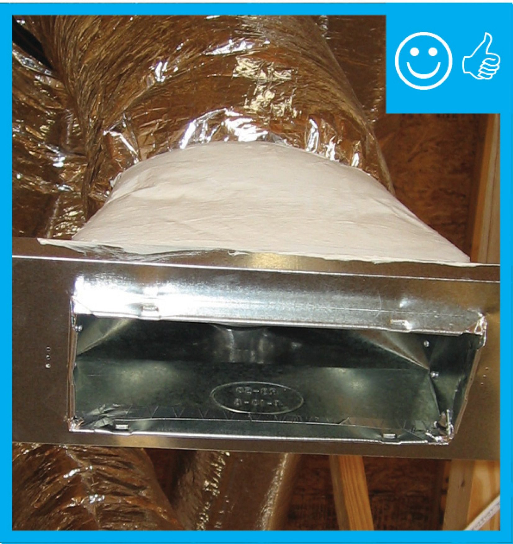
    Central forced air heating and cooling systems use ducts to distribute the hot and cold air. If these ducts have loose connections where sections of duct connect to each other or to duct boots or trunk lines or the air handler, air can leak through the cracks. Leaky ducts can be a major source of energy loss and comfort problems, and can contribute to moisture problems, especially when the ducts run through unconditioned space such as a vented attic or crawlspace.

    Building codes such as the International Residential Code (IRC 2015) and the International Energy Conservation Code (2015 IECC), and energy-efficiency programs like ENERGY STAR Single-Family New Homes require that if a home’s HVAC system includes a duct distribution system, the ducts must be tested for air leakage. Duct leakage is measured and documented by a certified home energy rater using a testing protocol approved by the Residential Energy Services Network, Inc. (RESNET). The accepted protocols are found in RESNET's Mortgage Industry National Home Energy Rating Systems Standards, Chapter 8, Section 803.3 (RESNET 2013).

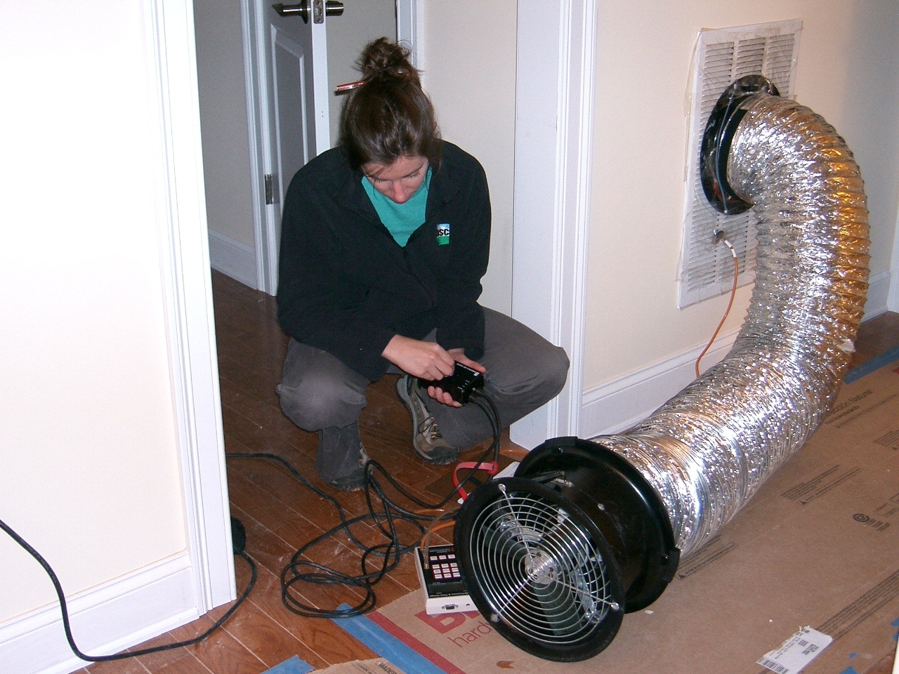
    As required by RESNET standards, the test is performed using a duct tester, such as the Minneapolis Duct Blaster or the Retrotec Duct Tester. The duct tester consists of three components: a calibrated fan that is used to either pressurize or depressurize the duct, a device called a manometer that is used to measure fan flow and building pressure, and supplies such as cardboard and tape or adhesive plastic sheeting to seal off the supply and return registers during the test (See Figure 1). The fan is used to pressurize or depressurize the duct system to 25 pascals (0.10 inch water column [IN WC]) (RESNET Standards). Once at 25 pascals pressure, the air flow through the duct tester is read in cubic feet of air flow per minute at 25 pascals; this measurement is abbreviated as CFM 25.

    Duct leakage testing should be performed after all components of the system have been installed, including the air handler, the ductwork, and the register boxes or duct boots.

    A technician conducts a duct blaster test.
    Figure 1. A technician conducts a duct blaster test.


    Two types of tests are performed: total duct leakage and leakage to the outdoors:

    The "duct leakage to the outdoors" test measures only duct leakage outside of the home’s air barrier, i.e., leakage to the outdoors, for example, into an unconditioned attic or crawlspace. The “total” duct leakage test measures how much air leakage there is for all of the ductwork connected to the HVAC system, including ducts located both outdoors and indoors.

    According to ENERGY STAR Single-Family New Homes (Version 3, Rev 11), for ducts in unconditioned spaces such as unconditioned vented attics or crawlspaces, both tests should be conducted. When all ducts are located in conditioned spaces, only the "total" duct leakage test needs to be conducted if certain conditions exist. Testing of duct leakage to the outdoors can be waived in accordance with the 2nd or 3rd alternative of ANSI / RESNET / ICC Std. 301, Table 4.2.2 (1), footnote (w). Alternatively, testing of duct leakage to outdoors can be waived in accordance with Section 5.5.2 of ANSI / RESNET / ICC Std. 380 if total duct leakage, at rough-in or final, is ≤ 4 CFM25 per 100 sq. ft. of conditioned floor area or 40 CFM25, whichever is larger. For ENERGY STAR criteria on testing of duct leakage to the outdoors, see Duct Leakage to Outdoors.

    ENERGY STAR (Version 3, Rev 11) allows total duct leakage to be tested at either rough-in or final. “Rough-in” is when the air handler and ducts have been installed and sealed but before drywall or flooring and registers are installed. (This includes cabinets (e.g., kitchen, bath, multimedia) or ductwork that connect duct boots to toe-kick registers.) “Final” is after the air handler and ducts, drywall and flooring, and registers have been installed. If testing is conducted at final, registers installed over carpets are permitted to be removed and the face of the duct boot temporarily sealed during testing.The Rater should also visually verify that the ductboots have been durably sealed to the subfloor (using duct mastic or caulk) to prevent leakage during normal operation. If testing is done at final, this visual check can be done then. If testing is done during rough-in, the rater must return after the drywall has been installed to visually confirm that the duct boot is sealed to the drywall.  If the ductblaster leakage testing is done at final, ducts should be visually inspected at rough-in to look for any obvious gaps or misses in duct mastic so those can be corrected before drywalling. Some raters will also recommend that the ducts be tested at rough-in with a low-CFM smoke machine connected to one of the ducts and the other registers closed off so that the HVAC contractor can clearly see and fix any leaks in the ducts.

    The ENERGY STAR Version 3 Rev 11 air leakage criteria specify that duct air leakage must be ≤ 4 CFM25 per 100 ft2 of conditioned floor area or ≤ 40 CFM25, whichever is greater, at rough-in or ≤ 8 CFM25 per 100 ft2 of conditioned floor area or ≤ 80 CFM25, whichever is greater, at final.

    There are pros and cons to either method. Some builders prefer to test for duct leakage at rough-in when the ducts are easier to access in case additional air sealing needs to be done. Some builders, especially those who install ducts in the attic, prefer to wait until final to test the ducts because the ducts are likely to get moved about by other trades in the meantime and ducts will still be accessible.

    One might question why duct leakage needs to be tested at all if the ducts and air handler are located in conditioned space. High-performance homes are homes built tight using materials that greatly retard heat transfer through conduction, convection, and radiation. As a result, high-performance homes require smaller HVAC systems. For example, 20 years ago, a 2,000-ft2 home required a 4- or 5-ton air conditioner for cooling. Today, a 2,000-ft2 home requires only a two-ton unit. This downsizing results in energy and cost savings. However, air handler fans have a standard air flow rate of 400 CFM per ton. If the system size is cut in half, the air flow is also cut in half. Therefore, it becomes even more important that the conditioned air not get lost in duct leakage.

    The measured duct leakage can be compared to rated air handler flow to get a sense of the energy penalty that duct leaks are contributing in Btu/h. (This is not an ENERGY STAR requirement.) Cooling systems move 400 cubic feet of air per minute over the evaporator coil per ton of cooling. Each cubic foot of air moved will carry with it 30 Btu/h. A 2.5-ton cooling system moves 1,000 CFM of air and puts out 30,000 Btu/h. If that system has a measured duct leakage of 10% (100 CFM25), it is losing 3,000 Btu/h (1/4 ton) of cooling to the outdoors.

    Leakage limits are assessed on a per-system, rather than per-home, basis. So, for example, if a home has two furnaces, duct leakage must be measured in each system and compared to the square footage that the system conditions. Each system must meet the “total” and “outdoors” leakage requirements to qualify for the ENERGY STAR program.

    How to Test "Total" Duct Leakage at Rough-In or Final

    1. For duct testing at rough-in, perform the test before drywall and finished flooring are installed, and after the air handler, ducts, and duct boots (register boxes) are installed. For duct testing at final, perform the test after the air handler, ducts and duct boots, drywall or finished flooring, and registers are installed. Connect the duct tester by attaching the duct that comes connected to the calibrated fan to a return duct grill with suitable tape (Figure 1). If conducting the test at rough-in, if there are any cabinets that connect duct boots to toe-kick registers, they do not need to be installed. If testing ducts at final, visually inspect the ducts prior to drywalling, to fix any obvious areas of leakage. A smoke test could also be conducted at this time to assist in making corrections before drywalling.
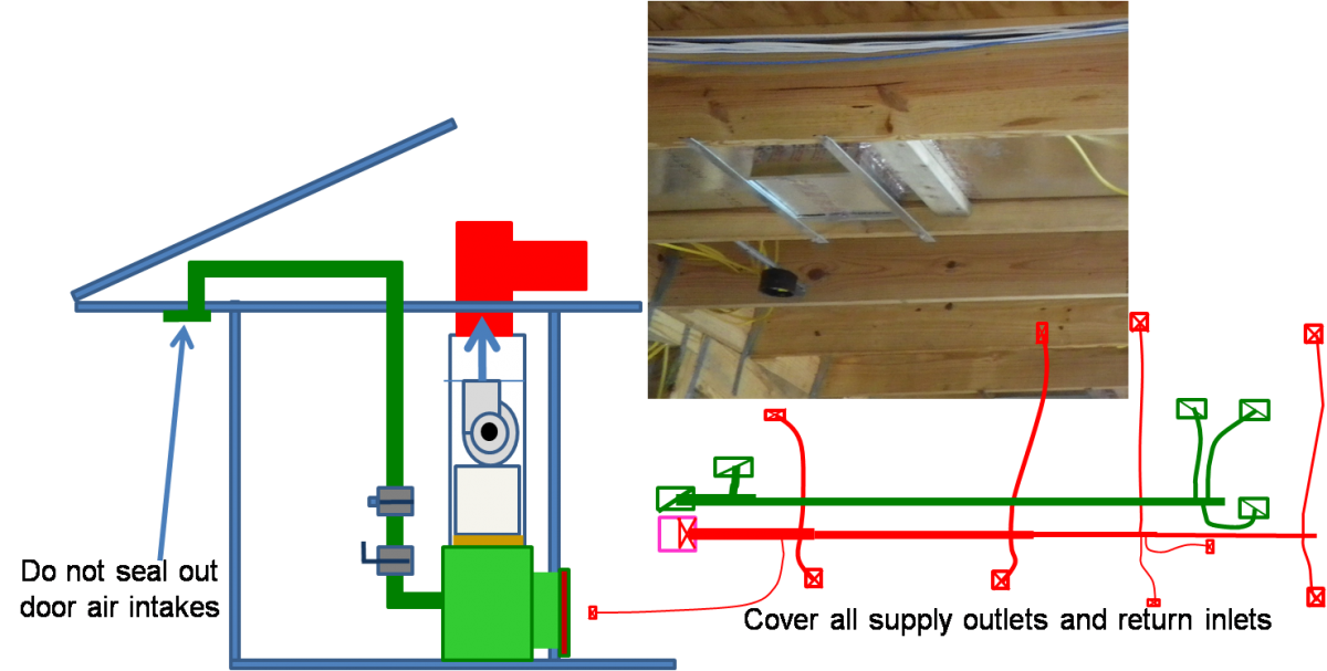
    2. Temporarily seal shut all of the other supply and return duct registers using cardboard and tape or removable adhesive plastic (Figures 2 and 3).
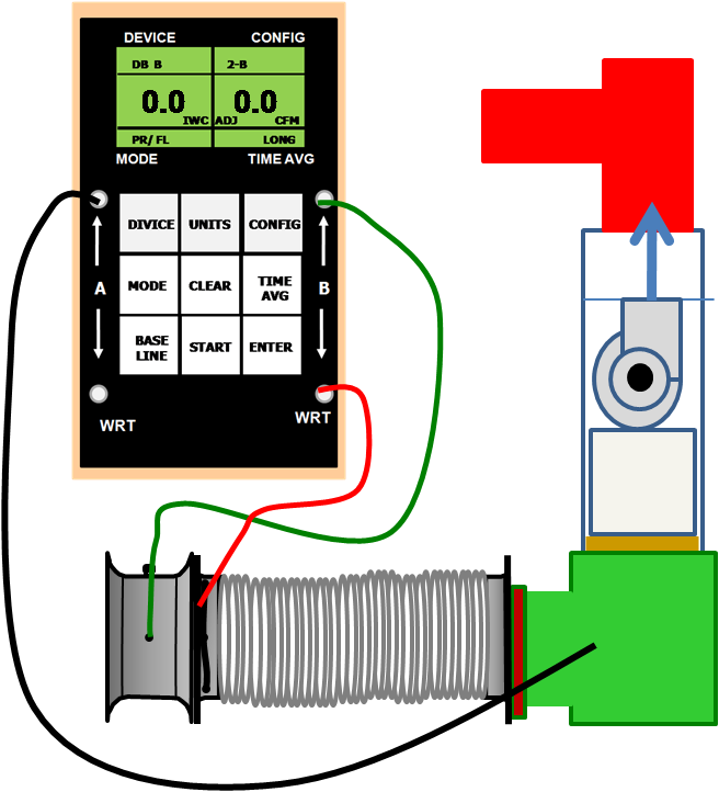
    3. Set up the duct tester to either pressurize or depressurize the duct system (follow manufacturer’s instructions). Set up the manometer to measure pressure and air flow according to the manufacturer’s instructions.
    4. Connect the "input" on the pressure side of the manometer to the return (the black tube in Figure 4).
    5. Turn on the fan to pressurize (or depressurize) the ductwork to 25 pascals. Leave at least one door or window open between the building and outside to prevent changes in building pressure.
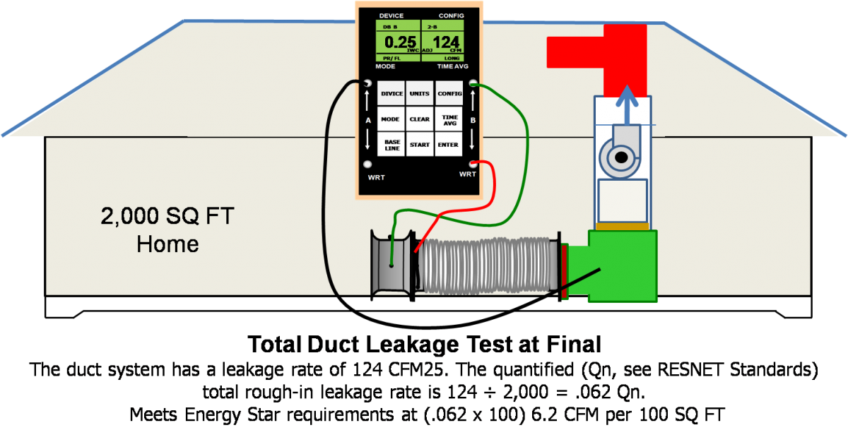
    6. Once a steady 25 pascals of pressure is reached in the duct system, note the manometer reading for CFM. This reading of the fan air flow needed to maintain 25 pascals of pressure is the amount of air escaping through the leaks in the duct system, indicated in cubic feet per minute.
    7. Reconnect the input (black tube in Figure 4) to a supply duct in a part of the house that is some distance from the return. Repeat steps 5 and 6. Record the duct leakage.
    8. Add the two duct leakage measurements together and divide by two. This will give the most accurate duct leakage measurement for total duct leakage. See the examples in Figures 5 and 6.)
    9. If duct leakage is too high, use a theatrical smoke machine to illustrate duct leakage locations to the HVAC contractor.
    10. The air handler unit can be sealed with tape to reduce air leakage.
    Total duct leakage preparation at rough-in.
    Figure 2. To prepare for a total duct test at rough-in, cover all of the supply outlets and return inslets.


    Total duct leakage prep at final.
    Figure 3. To prepare for a total duct test at final, cover all of the supply outlets and return inslets.


    Duct tester set up to depressurize duct system.
    Figure 4. The duct tester is set up to depressurize the duct system.


    Sample results at rough-n.
    Figure 5. Sample results from a total duct leakage test at rough-in.


    Sample test results at final.
    Figure 6. Sample results from a total duct leakage test at final.


    Success
    Ensuring Success

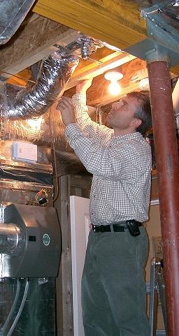
    After ducts are installed and before drywall is installed, the duct system should be visually inspected by a HERS rater to ensure that all duct connections are properly fastened and sealed, preferably with mastic. The rater should also visually inspect at rough-in that ducts are fully insulated (to R-8 for supply ducts and R-6 for returns and other ducts) along the length, including all connections, and that the insulation is not compressed by tight strapping, by framing members, or by excessive bending.

    If duct leakage is tested at rough-in, a HERS rater should confirm and document that total duct leakage is the greater of ≤ 4 CFM 25 per 100 ft2 of conditioned floor area or ≤ 40 CFM25 using a RESNET-approved testing protocol and should verify with a visual inspection that duct boots are sealed to finish surfaces at final.

    If duct leakage is tested at final, the HERS rater or builder may perform an optional, additional duct blaster test prior to drywall installation or make use of a theatrical smoke machine to look for air leaks so they can be sealed before drywalling.

    Climate
    Climate

    No climate specific information applies.

    Training
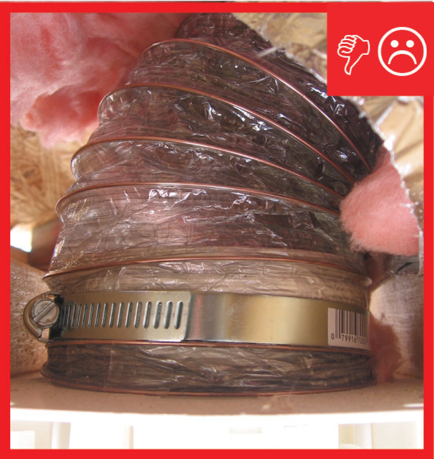
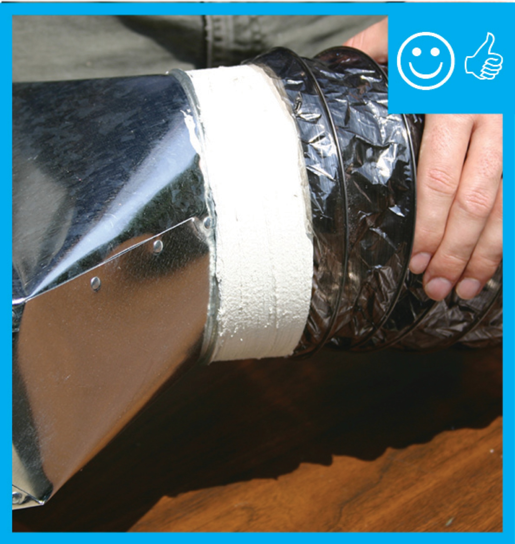
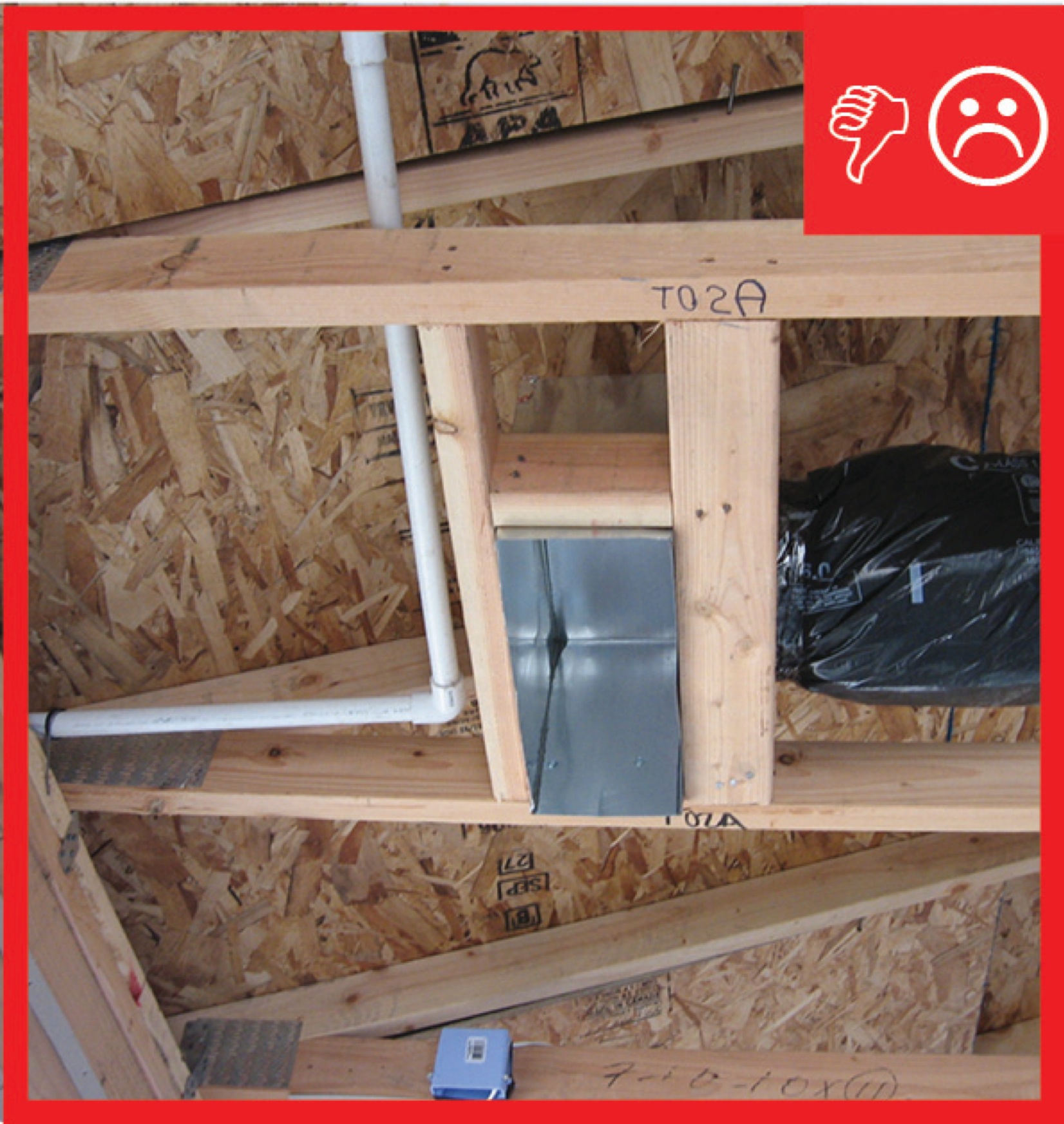
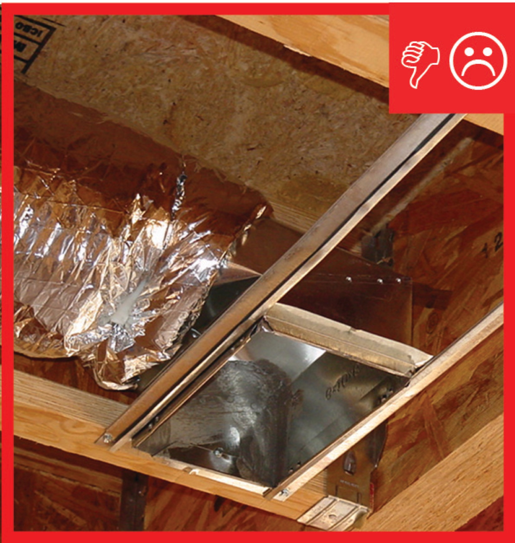
    Right and Wrong Images
    Image
    Connection in place but not sealed
    Connection in place but not sealed
    Image
    Mechanically fastened and sealed
    Mechanically fastened and sealed
    Image
    Insulation does not cover boot and is not sealed
    Insulation does not cover boot and is not sealed
    Image
    Insulation does not cover boot and is not sealed
    Insulation does not cover boot and is not sealed
    Image
    Boot has been covered with insulation and sealed with mastic
    Boot has been covered with insulation and sealed with mastic
    Videos
    Compliance

    Compliance

    The Compliance tab contains both program and code information. Code language is excerpted and summarized below. For exact code language, refer to the applicable code, which may require purchase from the publisher. While we continually update our database, links may have changed since posting. Please contact our webmaster if you find broken links.


    ENERGY STAR Single-Family New Homes, Version 3/3.1 (Rev. 11)

    National Rater Field Checklist

    HVAC System.
    6. Duct Quality Installation - Applies to Heating, Cooling, Ventilation, Exhaust, & Pressure Balancing Ducts, Unless Noted in Footnote.
    6.4 Rater-measured total duct leakage meets one of the following two options. Alternative in Footnote 40:39, 40, 41
    6.4.1 Rough-in: The greater of ≤ 4 CFM25 per 100 sq. ft. of CFA or ≤ 40 CFM25, with air handler & all ducts, building cavities used as ducts, & duct boots installed. All duct boots sealed to finished surface, Rater-verified at final.42
    6.4.2 Final: The greater of ≤ 8 CFM25 per 100 sq. ft. of CFA or ≤ 80 CFM25, with the air handler & all ducts, building cavities used as ducts, duct boots, & register grilles atop the finished surface (e.g., drywall, floor) installed.43

    Footnote 39) Items 6.4 and 6.5 generally apply to the ducts of space heating, space cooling, and dwelling unit mechanical ventilation systems. However, visual inspection is permitted in lieu of testing for a dwelling unit mechanical ventilation system not connected to the space heating or space cooling system, regardless of the number of dwelling units it serves. In such cases, a Rater shall visually verify that all seams and connections are sealed with mastic or metal tape and all duct boots are sealed to floor, wall, or ceiling using caulk, foam, or mastic tape. For duct systems requiring testing, duct leakage shall be determined and documented by a Rater using ANSI / RESNET / ICC Std. 380 including all Addenda and Normative Appendices, with new versions and Addenda implemented according to the schedule defined by the HCO that the home is being certified under. Leakage limits shall be assessed on a per-system, rather than per-home, basis.

    Footnote 40) For a duct system with three or more returns, the total Rater-measured duct leakage is permitted to be the greater of ≤ 6 CFM25 per 100 sq. ft. of CFA or ≤ 60 CFM25 at ‘rough-in’ or the greater of ≤ 12 CFM25 per 100 sq. ft. of CFA or ≤ 120 CFM25 at ‘final’.

    Footnote 41) Note that compliance with Item 6.4.1 or 6.4.2 in conjunction with Section 4a of the National Rater Design Review Checklist automatically achieves Grade I total duct leakage per ANSI / RESNET / ACCA Std. 310.

    Footnote 42) Cabinets (e.g., kitchen, bath, multimedia) or ducts that connect duct boots to toe-kick registers are not required to be in place during the ‘rough-in’ test.

    Footnote 43) Registers atop carpets are permitted to be removed and the face of the duct boot temporarily sealed during testing. In such cases, the Rater shall visually verify that the boot has been durably sealed to the subfloor (e.g., using duct mastic or caulk) to prevent leakage during normal operation.

    Please see the ENERGY STAR Single-Family New Homes Implementation Timeline for the program version and revision currently applicable in in your state.


    DOE Zero Energy Ready Home (Revision 07)

    Exhibit 1 Mandatory Requirements.
    Exhibit 1, Item 1) Certified under the ENERGY STAR Qualified Homes Program or the ENERGY STAR Multifamily New Construction Program.


    2009 International Energy Conservation Code (IECC)  /  2009 International Residential Code (IRC)

    IECC R403.2/IRC N1103.2 Ducts.

    IECC R403.2.1/IRC N1103.2.1 Insulation (Prescriptive). Supply ducts in attics shall be insulated to a minimum of R-8. All other ducts shall be insulated to a minimum of R-6.

                   Exception:  Ducts or portions thereof located completely inside the building thermal envelope.

    IECC R403.2.2/IRC N1103.2.2 Sealing (Mandatory).  All ducts, air handlers, filter boxes, and building cavities used as ducts shall be sealed.  Joints and seams shall comply with Section M1601.4 of the International Residential Code. [Exceptions may apply.]

                   Duct tightness shall be verified by either of the following:

    1. Post-construction test:  leakage to outdoors shall be less than or equal to 8 cfm (226.5 L/min) per 100 ft2 (9.29 m2) of conditioned floor area or a total leakage less than or equal to 12 cfm (339.8 L/min) per 100 ft2 of conditioned floor area when tested at a pressure differential of 0.1 inches w.g. (25 Pa) across the entire system, including the manufacturer’s air handler enclosure. All register boots shall be taped or otherwise sealed during the test.
    2. Rough-in test:  Total leakage shall be less than or equal to 6 cfm (169.9 L/min) per 100 ft2 of conditioned floor area when tested at a pressure differential of 0.1 inches w.g. (25 Pa) across the roughed in system, including the manufacturer’s air handler enclosure. All register boots shall be taped or otherwise sealed during the test. If the air handler is not installed at the time of the test, total leakage shall be less than or equal to 4 cfm (113.3 L/min) per 100 ft2 of conditioned floor area.

      Exceptions: Duct tightness test is not required if the air handler and all ducts are located within conditioned space.

    IECC R403.2.3/IRC N1103.2.3 Building cavities (Mandatory).  Building framing cavities shall not be used as supply ducts.

    2012 IECC  / 2012 IRC

    IECC R403.2/IRC N1103.2 Ducts.  Ducts and air handlers shall be in accordance with IECC R403.2.1 through R403.2.3 (IRC N1103.2.1-N1103.2.3).

    IECC R403.2.1/IRC N1103.2.1 Insulation (Prescriptive).  Same as 2009 IECC/IRC.

    IECC R403.2.2/IRC N1103.2.1 Sealing (Mandatory).  Ducts, air handlers, and filter boxes shall be sealed.  Joints and seams shall comply with either the International Mechanical Code or International Residential Code, as applicable [Exceptions may apply.]

    Exceptions:

    1. Air-impermeable spray foam products shall be permitted to be applied without additional joint seals.

    2. Where a duct connection is made that is partially inaccessible, three screws or rivets shall be equally spaced on the exposed portion of the joint so as to prevent a hinge effect.

    3. Continuously welded and locking-type longitudinal joints and seams in ducts operating at static pressures less than 2 inches of water column (500 PA) pressure classification shall not require additional closure systems.

    Duct tightness shall be verified by either of the following:

    1. Post-construction test: Total leakage shall be less than or equal to 4 cfm (113.3 L/min) per 100 ft2 (9.29 m2) of conditioned floor area when tested at a pressure differential of 0.1 inches w.g. (25 Pa) across the entire system, including the manufacturer’s air handler enclosure. All register boots shall be taped or otherwise sealed during the test.
    2. Rough-in test.  Total leakage shall be less than or equal to 4 cfm per (113.3 L/min) per 100 ft2 (9.29 m2) of conditioned floor area when tested at a pressure differential of 0.1 inches w.g. (25 Pa) across the system, including the manufacturer’s air handler enclosure. All registers shall be taped or otherwise sealed during the test. If the air handler is not installed at the time of the test, total leakage shall be less than or equal to 3 cfm (85 L/min) per 100 ft2 of conditioned floor area.

      Exception: The total leakage test is not required for ducts and air handlers located entirely within the building thermal envelope.

    IECC R403.2.2.1/IRC N1103.2.2.1 Sealed air handler.  Air handler shall have a manufacturer’s designation for an air leakage of no more than 2 percent of the design air flow rate when tested in accordance with ASHRAE 193.

    IECC R403.2.3/IRC N1103.2.3 Building cavities (Mandatory).  Building framing cavities shall not be used as ducts or plenums.

    20152018, and 2021 IECC  /  20152018, and 2021 IRC

    IECC R403.3/IRC N1103.3 Ducts.  Ducts and air handlers shall be in accordance with Sections R403.3.1 through R403.3.5 (IRC N1103.3.1-N1103.3.5).

    IECC R403.3.1/IRC N1103.3.1 Insulation (Prescriptive).  Supply and return ducts in attics shall be insulated to a minimum of R-8 where 3 inches (76 millimeters) in diameter and greater and R-6 where less than 3 inches (76 millimeters) in diameter.  Supply and return ducts in other portions of the building shall be insulated to a minimum of R-6 where 3 inches (76 millimeters) in diameter or greater and R-4.2 where less than 3 inches (76 millimeters) in diameter. In the 2021 IRC/IECC, ducts greater than 3 inches in diameter must be insulated to R-8 and ducts less than 3 inches in diameter must be insulated for R-6. 

    Exception:  Ducts or portions thereof located completely inside the building thermal envelope

    IECC R403.3.2/IRC N1103.3.2 Sealing (403.3.4 /N1103.3.4 in 2021 IECC/IRC) (Mandatory).  Ducts, air handlers, and filter boxes shall be sealed.  Joints and seams shall comply with either the International Mechanical Code or International Residential Code, as applicable.

    Exceptions [In 2015 IECC/IRC only; these exceptions were not included in the 2018 IECC/IRC.)

    1. Air-impermeable spray foam products shall be permitted to be applied without additional joint seals.
    2. For ducts having a static pressure classification of less than 2 inches of water column (500 Pa), additional closure systems shall not be required for continuously welded joints and seams, and locking-type joints and seams of other than the snap-lock and button-lock types.

    IECC R403.3.2.1/IRC N1103.3.2.1 Sealed Air Handler.  Air handlers shall have a manufacturer’s designation for an air leakage of no more than 2% of the design air flow rate when tested in accordance with ASHRAE 193.

    IECC R403.3.3/IRC N1103.3.3 (403.3.4.1/1103.3.4.1 in 2021 IECC/IRC) Duct testing (mandatory).  Ducts shall be pressure tested to determine air leakage by one of the following methods:

    1. Rough-in test.  Total leakage shall be measured with a pressure differential of
      0.1 inch water gage (25 Pa) across the system, including the manufacturer’s air handler enclosure if installed at the time of the test.  All registers shall be taped or otherwise sealed during the test.
    2. Post-construction test.  Total leakage shall be measured with a pressure differential of 0.1 inch water gage (25 Pa) across the entire system, including the manufacturer’s air handler enclosure.  Registers shall be taped or otherwise sealed during the test.

    Exception:

    A duct air leakage test shall not be required where the ducts and air handlers are located entirely within the building thermal envelope

     [New Exception added to 2018 and 2021 IECC/IRC] A duct air leakage test shall not be required for ducts serving heat or energy recovery ventilators that are not integrated with ducts serving heating or cooling systems.

    A written report of the results of the test shall be signed by the party conducting the test and provided to the code official.  [Because the ducts will be installed outside the building thermal envelope, this exception would not apply.]

    IECC R403.3.4/IRC N1103.3.4 (R403.3.6/N1103.3.6 in 2021 IECC/IRC) Duct leakage (Prescriptive).

    The total leakage of the ducts, where measured in accordance with Section R403.3.3, shall be as follows:

    1. Rough-in test.  The total leakage shall be less than or equal to 4 cfm per (113.3 L/min) per 100 ft2 (9.29 m2) of conditioned floor area where the air handler is installed at the time of the test. Where the air handler is not installed at the time of the test, the total leakage shall be less than or equal to 3 cfm (85 L/min) per 100 ft2 of conditioned floor area.
    2. Post-construction test: Total leakage shall be less than or equal to 4 cfm (113.3 L/min) per 100 ft2 (9.29 m2) of conditioned floor area.

    IECC R403.3.5/IRC N1103.3.5 (R403.3.7/N1103.3.7 in 2021 IECC/IRC) Building cavities (Mandatory). Building framing cavities shall not be used as ducts or plenums.

    2009, 2012, 20152018, and 2021 IRC

    Ducts are designed, constructed, and installed in accordance with the provisions of IRC M1601 and  M1602,  ACCA Manual D, and manufacturers’ guidance.    

    Retrofit:  2009, 2012, 2015, 2018,  and 2021 IECC

    Section R101.4.3 (in 2009 and 2012). Additions, alterations, renovations, or repairs shall conform to the provisions of this code, without requiring the unaltered portions of the existing building to comply with this code. (See code for additional requirements and exceptions.)

    Chapter 5 (in 2015, 2018, 2021). The provisions of this chapter shall control the alteration, repair, addition, and change of occupancy of existing buildings and structures.

    Retrofit:  2009, 2012, 2015, 2018,  and 2021 IRC

    Section R102.7.1 Additions, alterations, or repairs. Additions, alterations, renovations, or repairs shall conform to the provisions of this code, without requiring the unaltered portions of the existing building to comply with the requirements of this code, unless otherwise stated. (See code for additional requirements and exceptions.)

    Appendix J regulates the repair, renovation, alteration, and reconstruction of existing buildings and is intended to encourage their continued safe use.

    Retrofit
    Existing Homes

    The information provided for testing duct leakage in new homes applies to testing duct leakage in existing homes as well.

    For more on duct sealing, see the U.S. Department of Energy’s Standard Work Specifications.

    See Compliance tab. 

    More

    More Info.

    Access to some references may require purchase from the publisher. While we continually update our database, links may have changed since posting. Please contact our webmaster if you find broken links.

    References and Resources*
    Author(s)
    Air Conditioning Contractors of America
    Organization(s)
    ACCA
    Publication Date
    Description
    Standard outlining industry procedure for sizing residential duct systems.
    Author(s)
    RESNET
    Organization(s)
    RESNET
    Publication Date
    Description
    RESNET standards aimed to ensure that accurate and consistent home energy ratings are performed by accredited home energy rating providers through their raters nationwide.
    *For non-dated media, such as websites, the date listed is the date accessed.
    Contributors to this Guide

    The following authors and organizations contributed to the content in this Guide.

    Sales
    Building Science Measures
    Building Science-to-Sales Translator

    HVAC System Diagnostics (New or Existing Homes) = Certified Comfort System

    Image(s)
    Technical Description

    Even good installers can miss things. Once the home’s comfort system has been installed, it should be tested to make sure it is operating properly. Organizations like the Residential Energy Services Network (RESNET) and North America Technician Excellence (NATE) train home energy raters to test homes for HVAC performance, as well as for energy efficiency, health, safety, and durability. Testing by these certified third-party home raters can verify that a home is meeting the HVAC and other performance requirements of state and local building codes and of home-performance programs like ENERGY STAR Certified Homes.

    Certified Comfort System
    Sales Message

    Certified comfort systems are installed by accredited contractors and independently verified for professional installation. What this means to you is greater assurance your home’s comfort system is installed to the highest standards. Wouldn’t you agree comfort is too important to leave to chance?

    Last Updated

    Mobile Field Kit

    The Building America Field Kit allows you to save items to your profile for review or use on-site.

    Sign Up  or  Log In

    Did you find this information helpful?

    If you have questions and/or would like a reply to this feedback, please include your e-mail address in the message.
    This question is for testing whether or not you are a human visitor and to prevent automated spam submissions.