

Scope
Air seal around all duct shafts and flues installed through ceilings, walls, and flooring to keep conditioned air from leaking into unconditioned space.
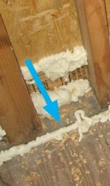
- To air-seal around duct shafts, use caulk, canned foam, or rigid air barrier material cut to fit and caulked or foamed in place around the duct shafts.
- To air-seal around combustion flues, use fire-rated caulk and UL-rated collars or sheet metal cut to fit and sealed with fire-rated caulk, while maintaining proper clearance between flue and combustible materials.
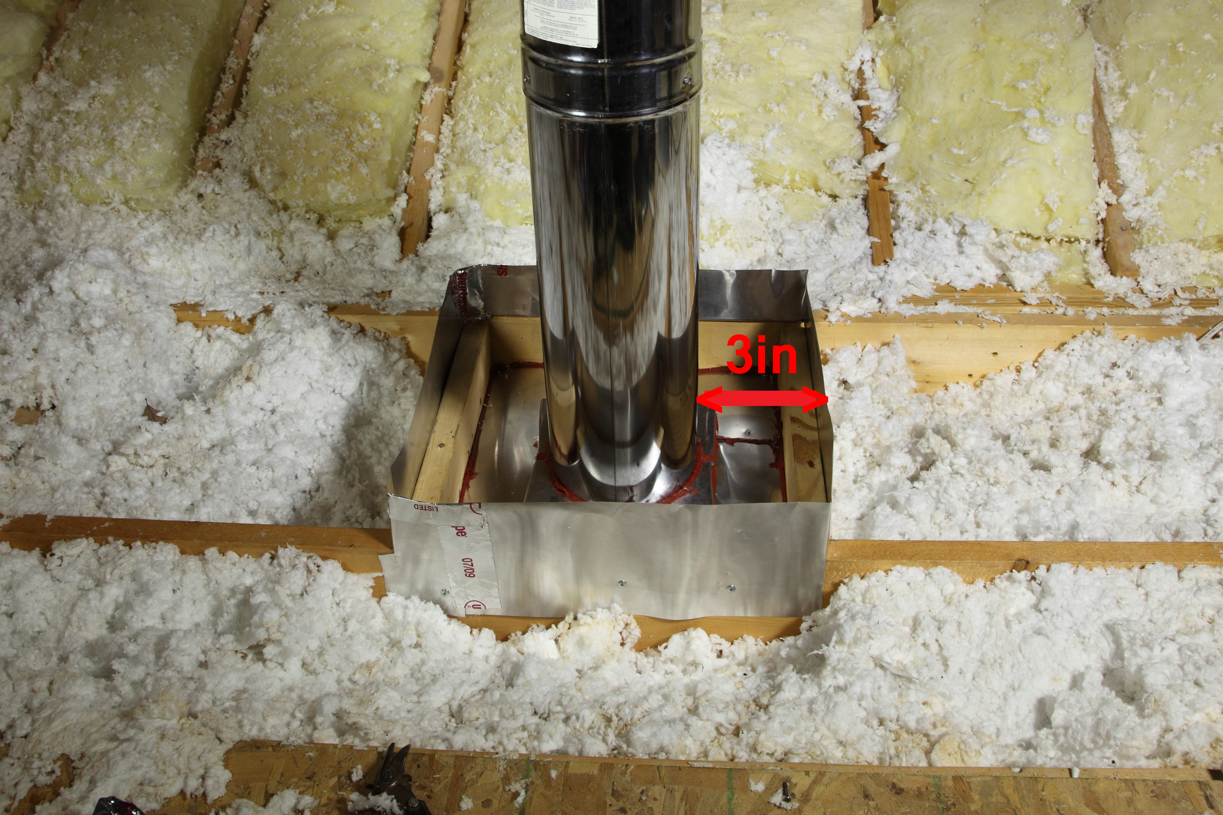
- Construct a sheet metal shield around combustion flues to maintain 3 inches of clearance between the flue and attic insulation. Make the shield 4 inches higher than the expected insulation height.
See the Compliance Tab for links to related codes and standards and voluntary federal energy-efficiency program requirements.
Description
Install air barriers around duct and flue shafts in the attic floor to prevent air leakage between the living space and the attic and to allow full insulation levels to be installed around the duct or flue. Air barrier material around duct shafts can include thin sheet goods such as rigid insulation, dry wall, OSB, or plywood. Air barriers around flue shafts should be made of a heat-resistant material such as sheet metal. These materials may be installed by insulators, framers, or drywallers. This task should be included in the contract for the appropriate trade depending on the workflow at specific job sites.
Air barrier effectiveness is measured at the whole-house level. High-performance branding programs and the IECC code require that builders meet specified infiltration rates at the whole-house level. See the Compliance tab for these specified infiltration rates.
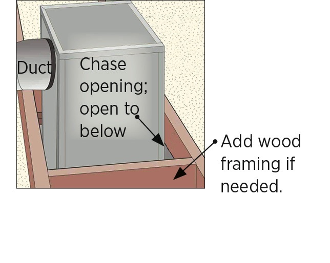
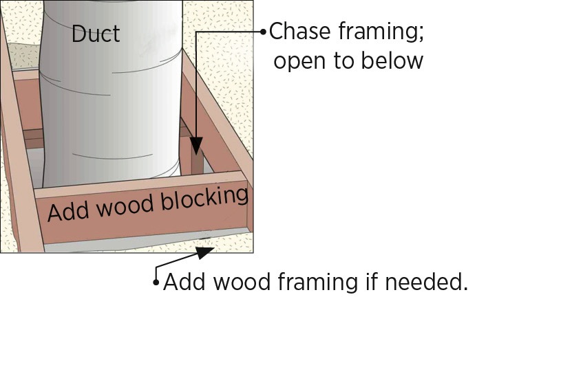
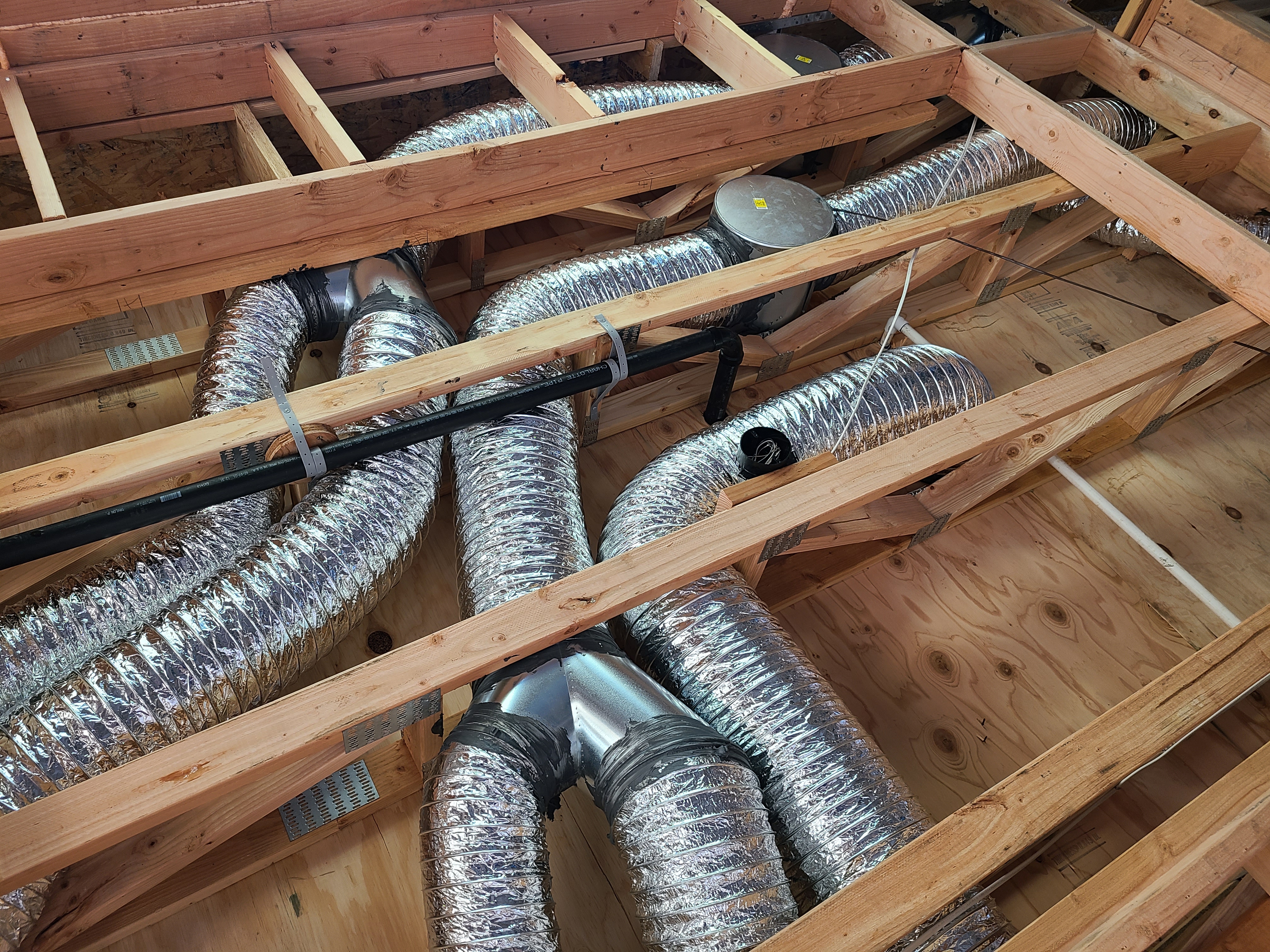
How to Seal a Rigid Duct Chase
1. Install wood framing cross pieces in the attic rafter bays on each side of the duct chase, if needed.
Source
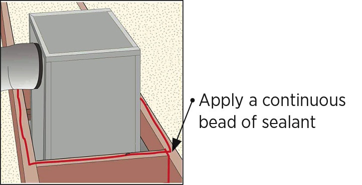
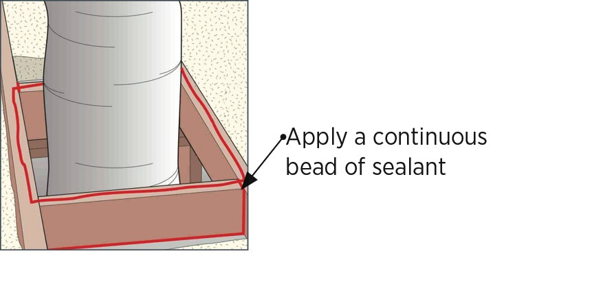
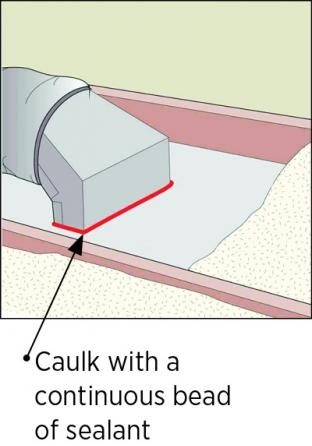
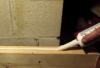
2. Seal all wood framing joints surrounding the chase with sealant. Lay a generous continuous bead of sealant along the top edge of the chase framing.
Source
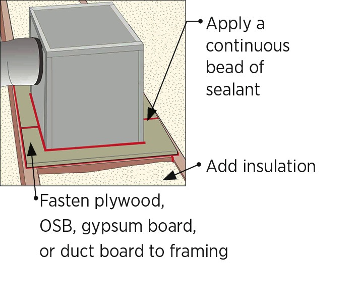
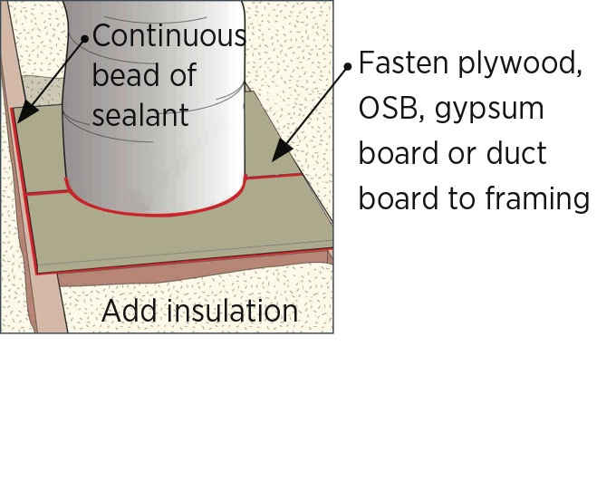
3. Measure and cut the air-blocking material (plywood, rigid foam, or drywall) to fit around the duct. Place the blocking material on the framing leaving a 1/4-in. gap between the rigid duct and the material. Fasten the material in place with nails or screws. Seal the material to the duct with sealant. Also seal any joints in the blocking material. Cover the material with insulation to the specified attic insulation depth.
Source
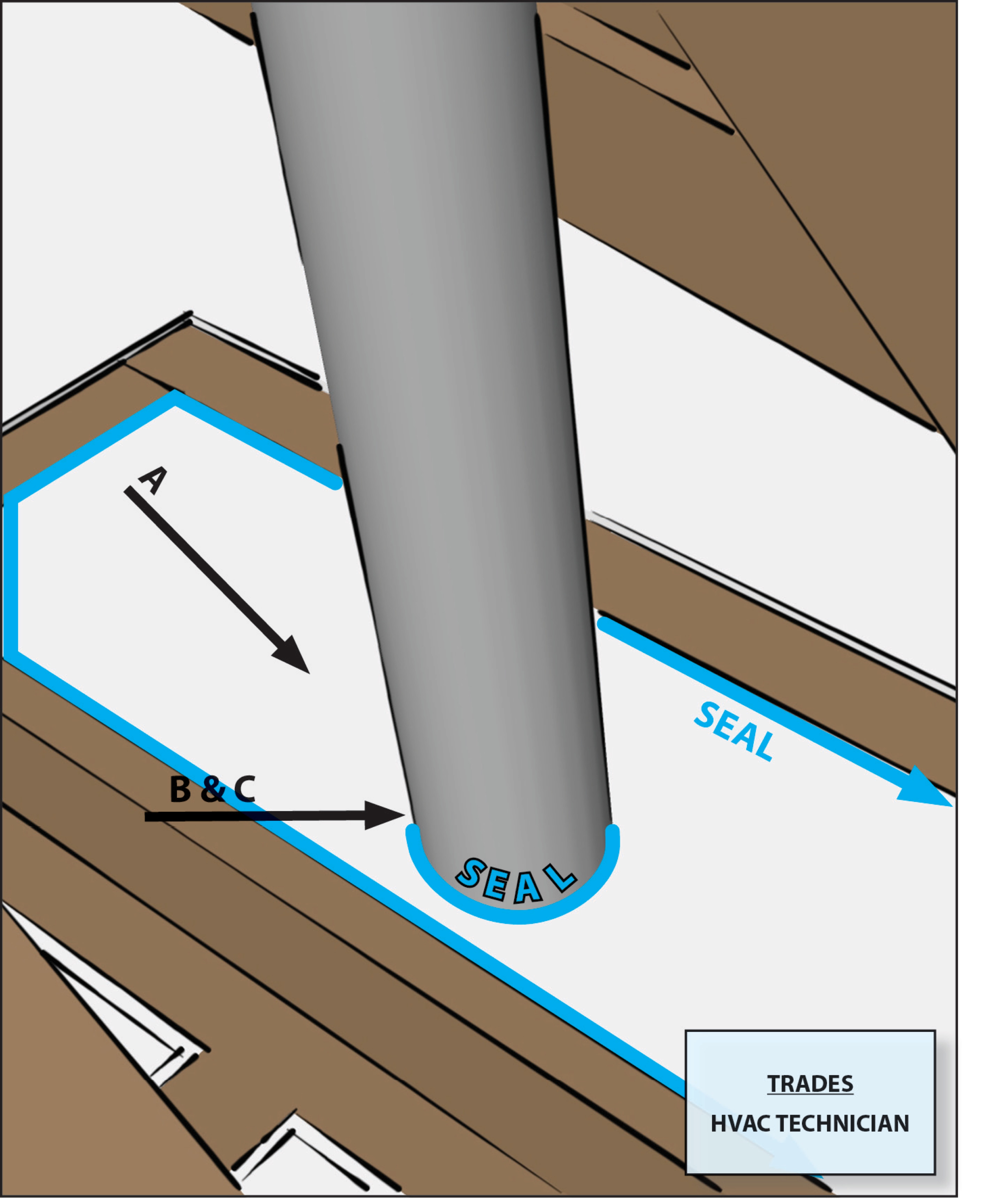
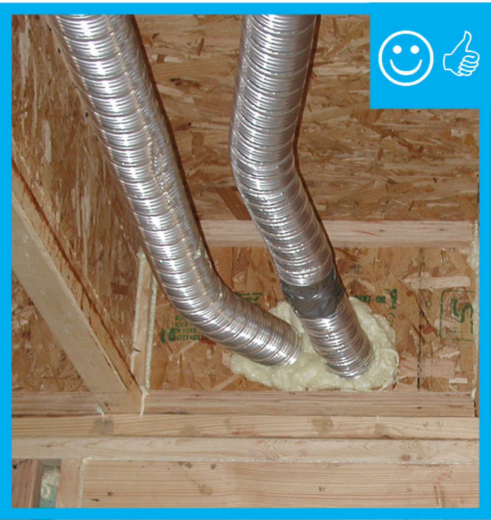
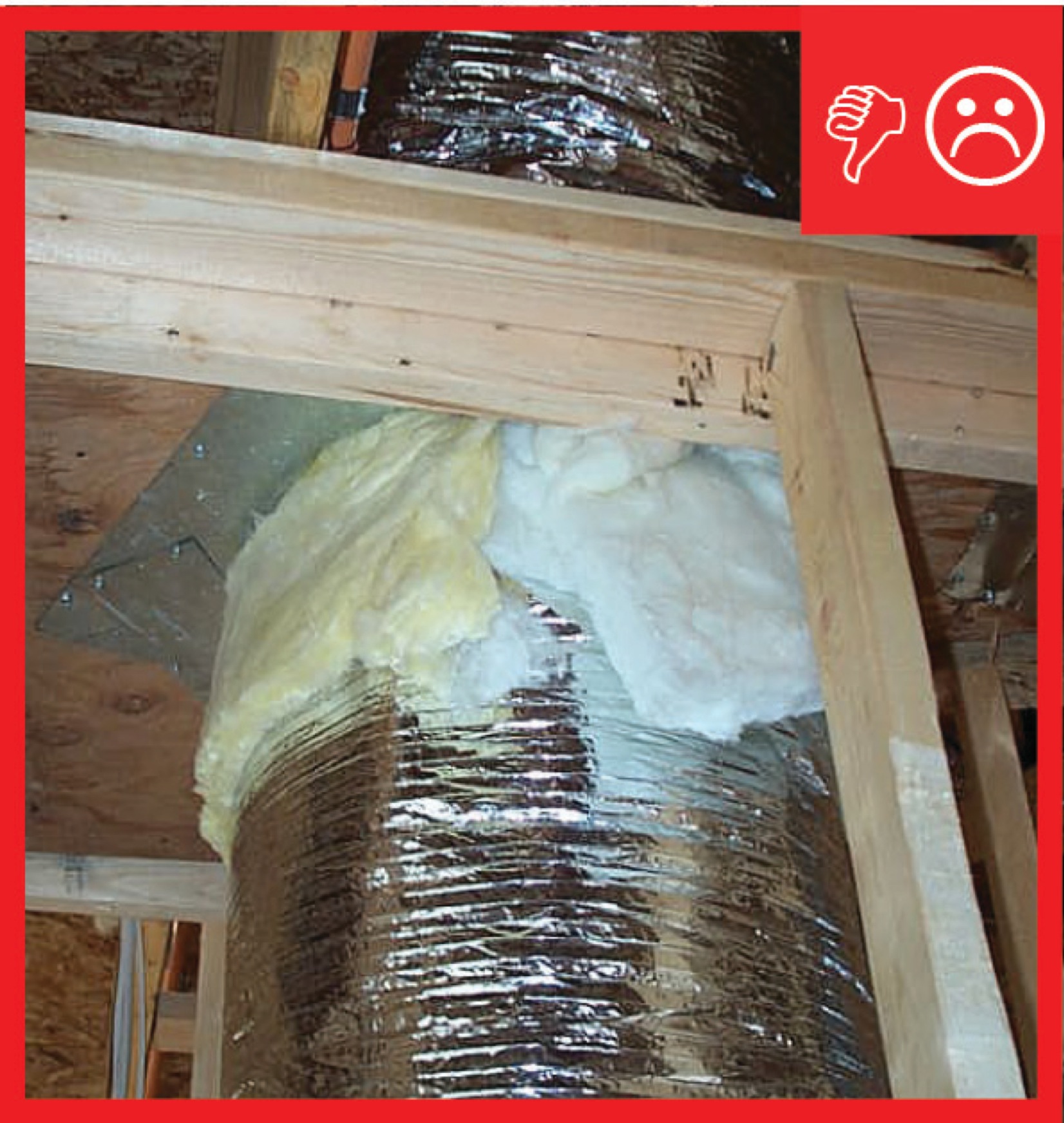
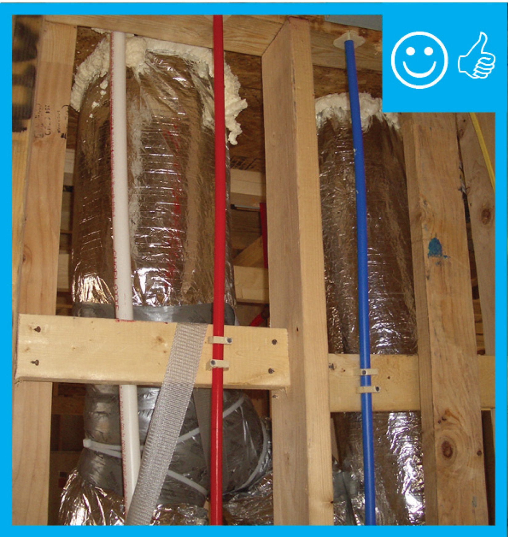
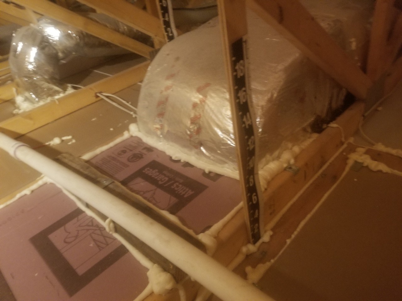
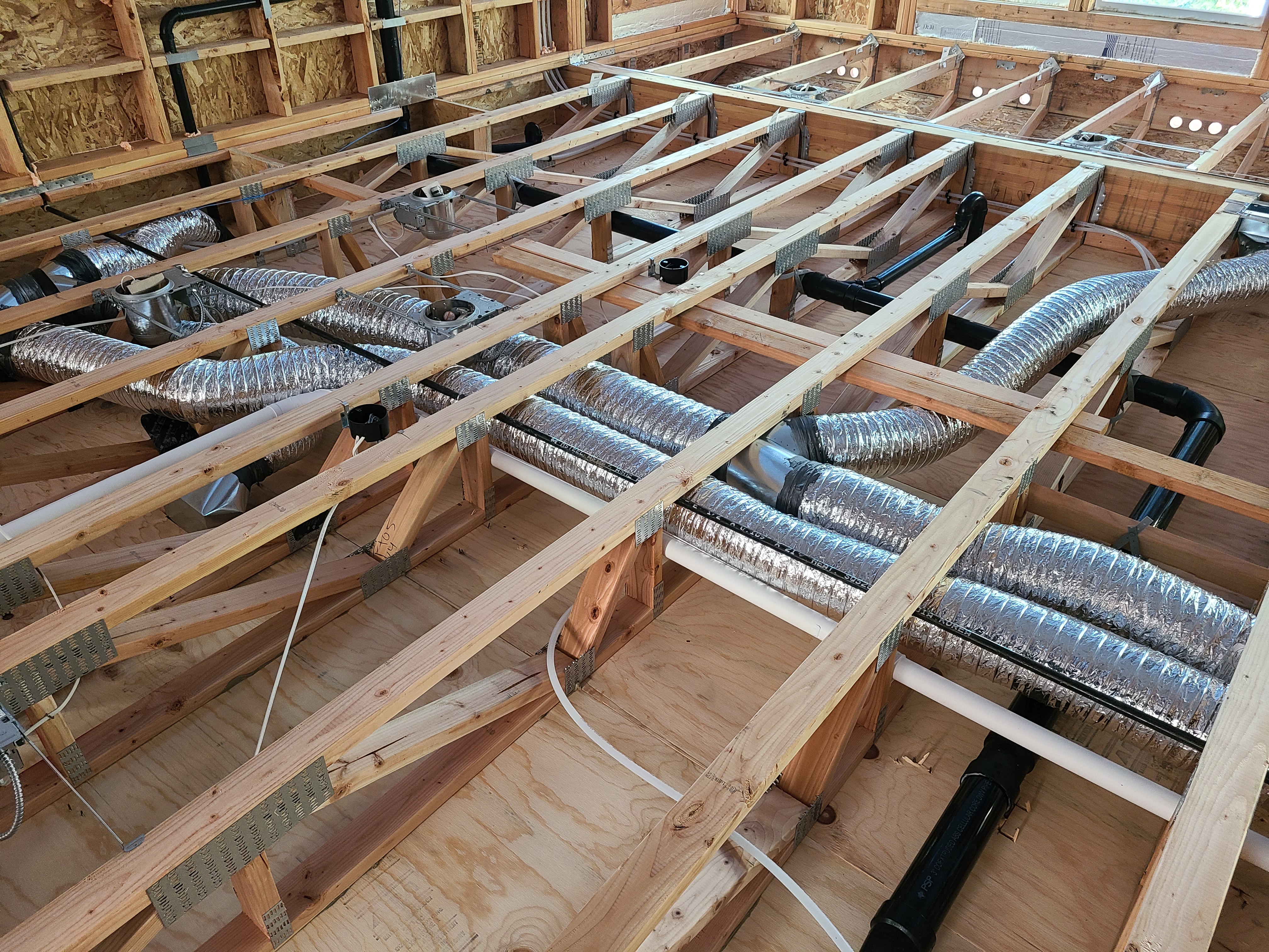
How to Air Seal a Flex Duct Chase
1. Install wood framing cross pieces in the attic rafter bays on each side of the duct chase, if needed.
Source
2. Seal all wood framing joints surrounding the chase with sealant. Lay a generous continuous bead of sealant along the top edge of the chase framing.
Source
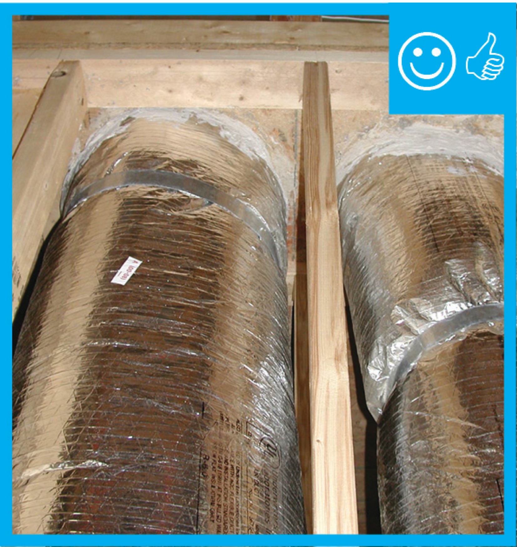
3. Measure and cut the air-blocking material (plywood, rigid foam, or drywall) to fit around the duct. Cut the material into two halves and then cut half circles in each to encompass the flex duct. Place the blocking material on the framing and in contact with the duct. Fasten the material with nails or screws. Seal the blocking material to the duct with sealant. Also seal the joints in the blocking material. Cover the blocking material with insulation to the required levels.
Source
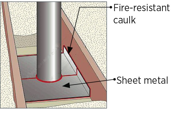
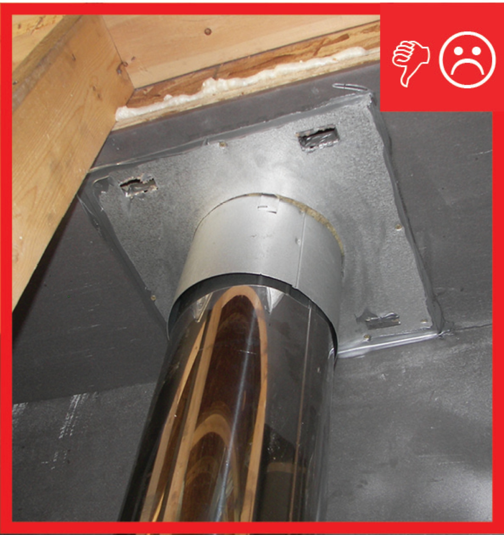
How to Air Seal a Metal Chimney or Flue Vent Pipe – Option 1 – Air Seal at the Bottom of the Framing
1. Cut two pieces of sheet metal to cover the chase opening. Allow 1 inch of overlap. Fasten the sheet metal to the framing and seal all edges and seams with fire-rated caulk.
Source
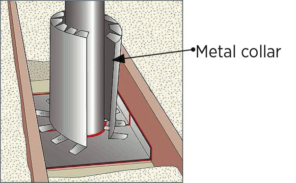
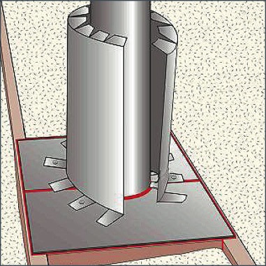
2. Use sheet metal to make a shield that will wrap around the pipe with a 3-inch clearance. Fold in the tabs at the top and every other tab at the bottom to maintain a 3-inch clearance. With tabs folded, the shield should be 4 inches taller than the finished insulation level. Seal the edges together with fire-rated caulk.
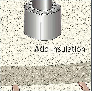
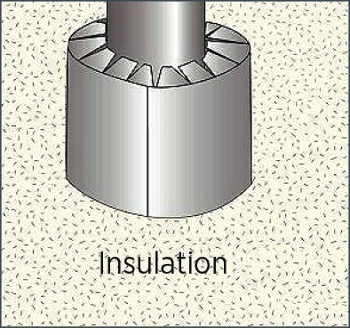
3. Cover the shield with insulation to the required height. The insulation should cover the rafters.
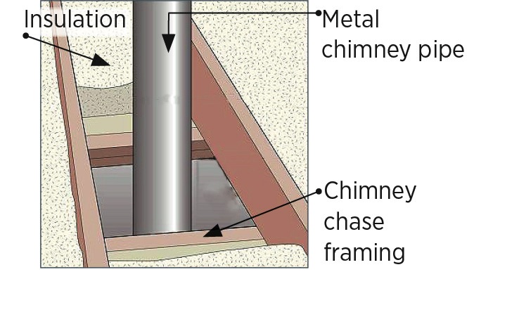
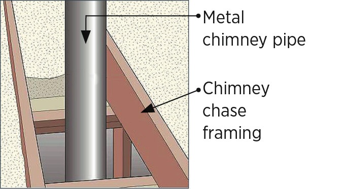
How to Air Seal a Metal Chimney or Flue Vent Pipe – Option 2 – Air Seal at the Top of the Framing
1. Cut two pieces of framing lumber equal in height to the ceiling joists. Fasten wood cross pieces to joists keeping at least 3 inches of clearance to the pipe. Caulk this wood blocking to the framing.
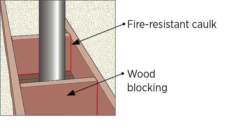
Source
2. Cut two pieces of sheet metal or aluminum flashing to fit around the chimney pipe with 1 inch of overlap. Fasten the sheet metal to the framing and seal all edges and seams with fire-rated caulk.
Source
3. Use sheet metal to make a shield that will wrap around the pipe with a 3-inch clearance. Fold in tabs at the top and every other tab at the bottom to maintain a 3-inch clearance. With tabs folded, the shield should be 4 inches taller than finished insulation level. Seal the edges together with fire-rated caulk.
Source
4. Cover the shield with insulation to the required height.
Source
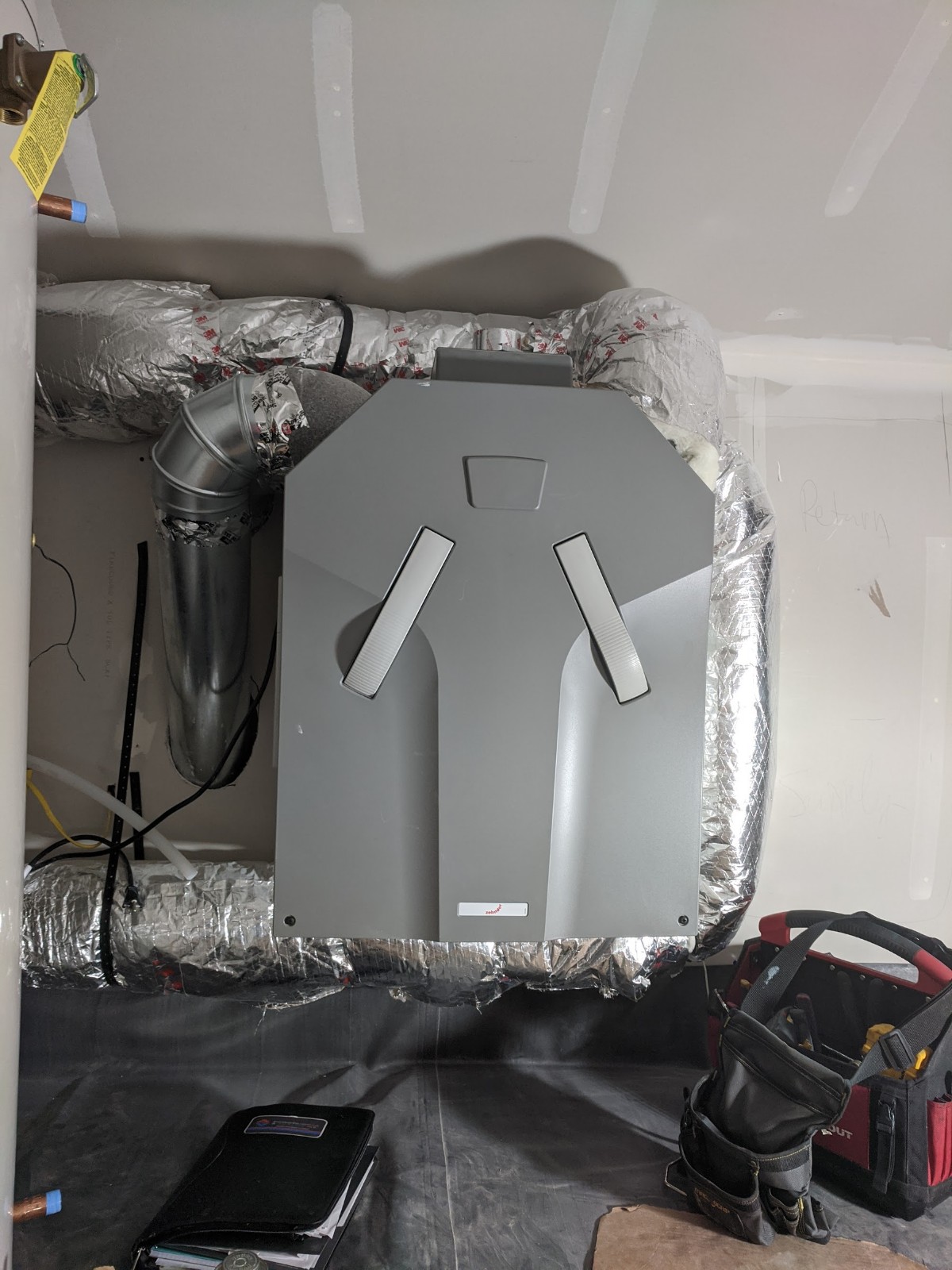
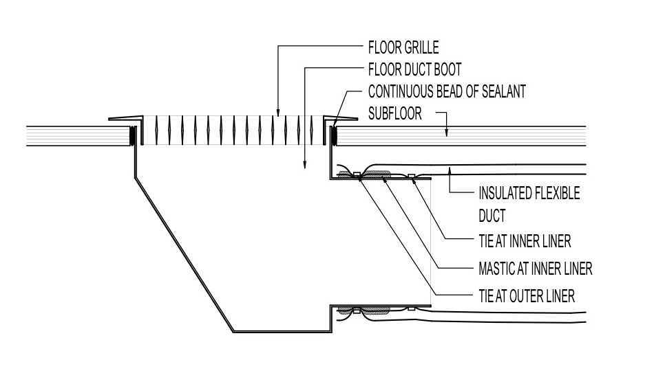
How to Seal a Duct Boot to the Ceiling
1. Seal all sides of the duct boot to the gypsum board with spray foam or caulk. Apply mastic or metal tape to all duct seams and joints.
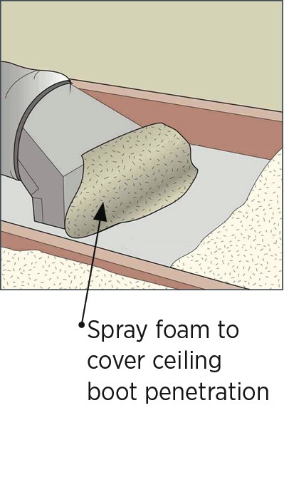
2. Add insulation to the specified attic insulation depth.
Ensuring Success
Blower door testing, which is conducted as part of the whole-house energy performance test-out, may help indicate whether duct and flue openings to unconditioned space (such as an attic) have been successfully sealed. An infrared camera can be used in conjunction with the blower door testing to detect air leakage and heat loss at the duct and flue shaft openings, if a sufficient temperature difference exists between the unconditioned and the conditioned space of the house. An experienced technician can also check for air leaks beneath the knee walls with a smoke pencil or by feeling with the back of the hand.
Region
No climate specific information applies.
Training
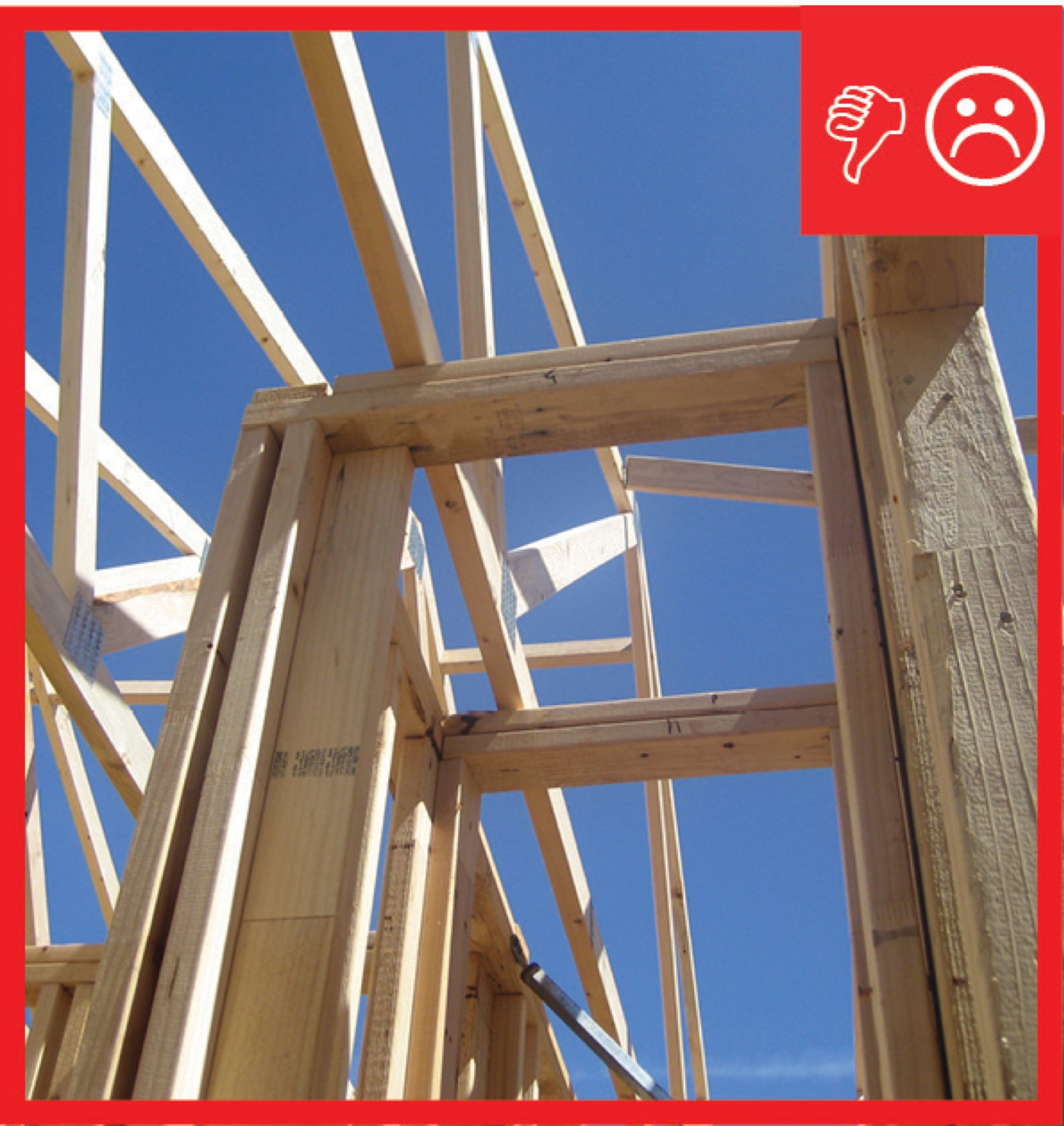
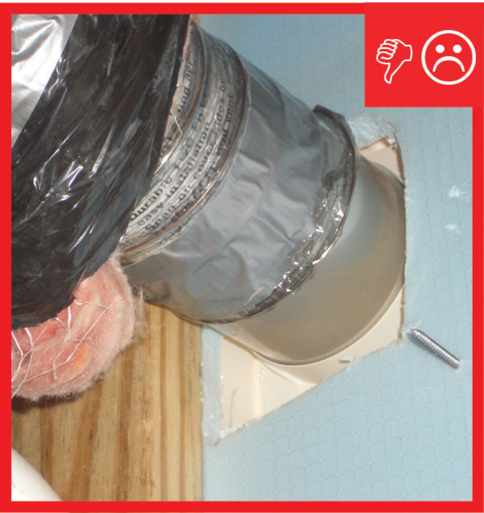
Right and Wrong Images
Source
Guide describing details that serve as a visual reference for each of the line items in the Thermal Enclosure System Rater Checklist.
Source
Guide describing details that serve as a visual reference for each of the line items in the Thermal Enclosure System Rater Checklist.
Source
Guide describing details that serve as a visual reference for each of the line items in the Thermal Enclosure System Rater Checklist.
Source
Guide describing details that serve as a visual reference for each of the line items in the Thermal Enclosure System Rater Checklist.
Source
Guide describing details that serve as a visual reference for each of the line items in the Thermal Enclosure System Rater Checklist.
Source
Guide describing details that serve as a visual reference for each of the line items in the Thermal Enclosure System Rater Checklist.
Source
Guide describing details that serve as a visual reference for each of the line items in the Thermal Enclosure System Rater Checklist.
Source
Source
Source
Source
Videos

CAD Files

Compliance
Retrofit
SCOPE
In existing homes, air seal and insulate around new or existing duct and flue shafts to minimize air leakage to and from unconditioned attics.
- Remove any existing insulation from around the duct or flue shaft. Inspect the attic floor around the duct and flue shafts for air and water leaks. Repair or replace any damaged materials. Add air sealing and/or insulation as needed.
- See the Scope and Description tab for additional instructions.
For more information on conditions that may be encountered when working in existing attics, see the Pre-Retrofit Assessment of Attics, Ceilings, and Roofs. Also see the U.S. Department of Energy’s Standard Work Specifications (SWS) guidance on air sealing chases and ceiling penetrations.
DESCRIPTION
- Inspect around ducts and flue shafts for water damage and air leaks. Repair or replace any damaged materials. Add air sealing and/or insulation, as needed.
- See the Description tab for additional installation information.
COMPLIANCE
Alterations
2009 IECC and 2009 IRC, 2012 IECC and 2012 IRC
2012 IECC, Section R101.4.3 / 2012 IRC N1101.3 and 2009 IECC 101.4.3 / 2009 IRC N1101.4.3 Alterations – General. Alterations to an existing building or portion of a building should comply with the provisions of the code as they relate to new construction without requiring unaltered portion(s) of the existing building to comply with this code.
2015 IECC and 2015 IRC, 2018 IECC and 2018 IRC
2015 IECC/2015 IRC, Section R501.1.1/N1107.1.1 Existing Buildings – General. Alterations to an existing building or portion of a building should comply with Sections R502/N1108, R503/N1109, or R504/N1110. Unaltered portions of the existing building are not required to comply.
R503.1/N1109.1 Alterations. General. Alterations to any building or structure should comply with the requirements of the code for new construction. Alterations should not negatively impact conformance of a building or structure to the provisions of this code; that is, code conformance should be the same as existed for the building or structure prior to the alteration. Alterations should not create an unsafe or hazardous condition or overload existing building systems. Alterations should be such that the altered building or structure uses no more energy than the existing building or structure prior to the alteration.
See Compliance tab.
More Info
Case Studies
References and Resources
*For non-dated media, such as websites, the date listed is the date accessed.
Contributors to this Guide
The following authors and organizations contributed to the content in this Guide.
Pacific Northwest National Laboratory
Building Science Corporation, lead for the Building Science Consortium (BSC), a DOE Building America Research Team
Sales
Tight Air Sealed Home = Comprehensive Draft Protection
Technical Description
Poorly air-sealed homes are less comfortable and cost more to maintain because they provide a pathway for drafts, cold spots, moisture, and insects into the home. Comprehensive draft protection includes a continuous air barrier around the whole house along with caulking and sealing in all holes and cracks. This includes around wiring, plumbing, ducts, and flues; where wall framing meets flooring; around windows; where drywall meets top plates and sill plates; where rim joists meet foundation walls and subfloors; etc. Spray foam insulation can be used at rim joists, floors above unconditioned space, and in attics to insulate and air seal at the same time.
Questions? Comments? Contact our webmaster.