

Scope
If the home contains natural-draft appliances (such as a natural-draft furnace, boiler, or water heater) then combustion safety testing must be conducted by a certified energy rater (as required by the NFPA 54).
See the Compliance Tab for links to related codes and standards and voluntary federal energy-efficiency program requirements.
Description
If a home's furnace, boiler, and/or water heater is installed within the home’s pressure boundary (i.e., within the thermal envelope), this equipment should be direct-vent/sealed-combustion equipment. (See the Building America Solution Center guides Direct Vent Equipment and Combustion Furnaces for more information.) ENERGY STAR permits non-direct-vented combustion appliances in Climate Zones 1, 2, and 3. If non-direct vented appliances (also known as atmospheric-vented or Category 1 appliances) are installed in a confined space or an air-tight building, two fresh air supply ducts or openings must be installed to provide combustion air in the combustion appliance zone (CAZ) as described below and as required by NFPA 54, Sections 5.3.3 and 5.3.4. Providing the correct amount of combustion and dilution air for Category I furnaces, boilers, and water heaters is paramount for safe and efficient operation. Combustion dilution air should come from outdoors but it is also legal for combustion air to come from the CAZ, provided there is enough air volume in the CAZ.
The National Fuel Gas Code describes several methods for providing combustion air to the CAZ; these are shown in Figures 1 through 5.
Configurations of Combustion Appliance Zones
Appliances should be installed in a zone or room that can be sealed from the indoor space and communicated to the outdoors through openings in the wall or ducts that connect to the outdoors. This room could include:
- A mechanical closet that opens or vents to the outdoors.
- A separate room open to the outdoors.
Note that basements and crawl spaces are not good spaces for zone isolation. If a basement or crawl space must be used as the location for an atmospherically vented combustion appliance, to ensure proper zone isolation, follow these steps:
- Ensure that there are no cracks, gaps, or openings in the physical boundary of the zone so that it is completely air-tight relative to the living space.
- Make sure that duct or furnace cabinets located in the zone are sealed to prevent air leakage and to avoid the movement of air from the zone to the living space.
- In retrofit situations, if an atmospheric combustion appliance will be installed in a basement or crawlspace, remove all exhaust devices (e.g. exhaust fans, fireplaces, clothes dryers) or provide additional makeup air to adequately serve all of the exhaust devices in the zone.
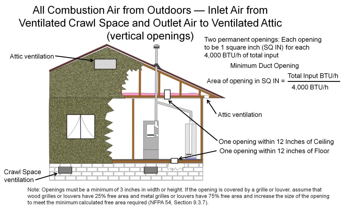
Option 1. Combustion air vertical ducts through floor and ceiling - Combustion air can be drawn through vertical ducts in the floor and ceiling (see Figure 1) with one duct through the floor to the vented crawlspace and one duct through the ceiling to the vented attic. The duct into the attic terminates above the attic insulation. The interior openings should be within 12 inches of the ceiling and within 12 inches of the floor. The minimum net free area of each opening should be one square inch per 4,000 Btu/h of the total input of all the appliances in the zone. Be sure to account for louvers, screens, or grilles.
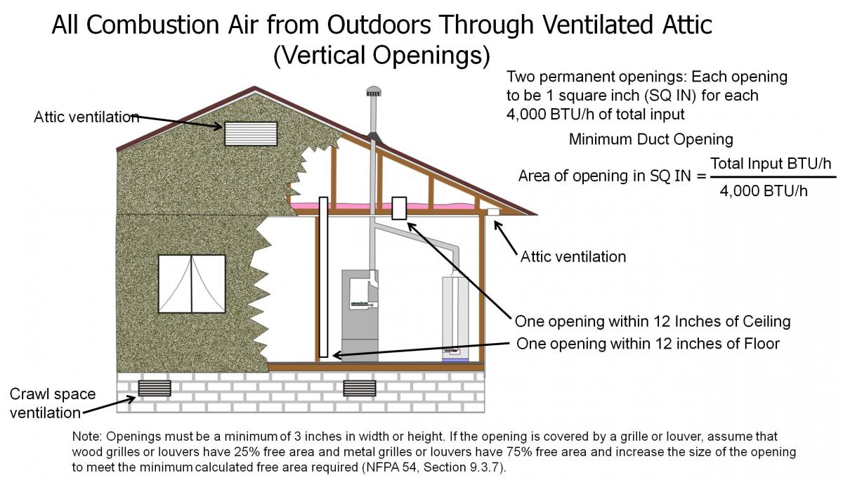
Option 2. Combustion air vertical ducts through attic to vented ceiling – Figure 2 shows two vertical ducts through the ceiling to the vented attic. One hole is located in the ceiling with the duct terminating above the insulation. The second duct extends from a point within 12 inches of the floor and extending up through the ceiling and terminating above the insulation in the attic. The minimum net free area of each opening should be one square inch per 4,000 Btu/h of the total input of all the appliances in the zone. The same duct opening calculation is used for Figure 2 as for Figure 1. Be sure to account for louvers, screens, or grilles.
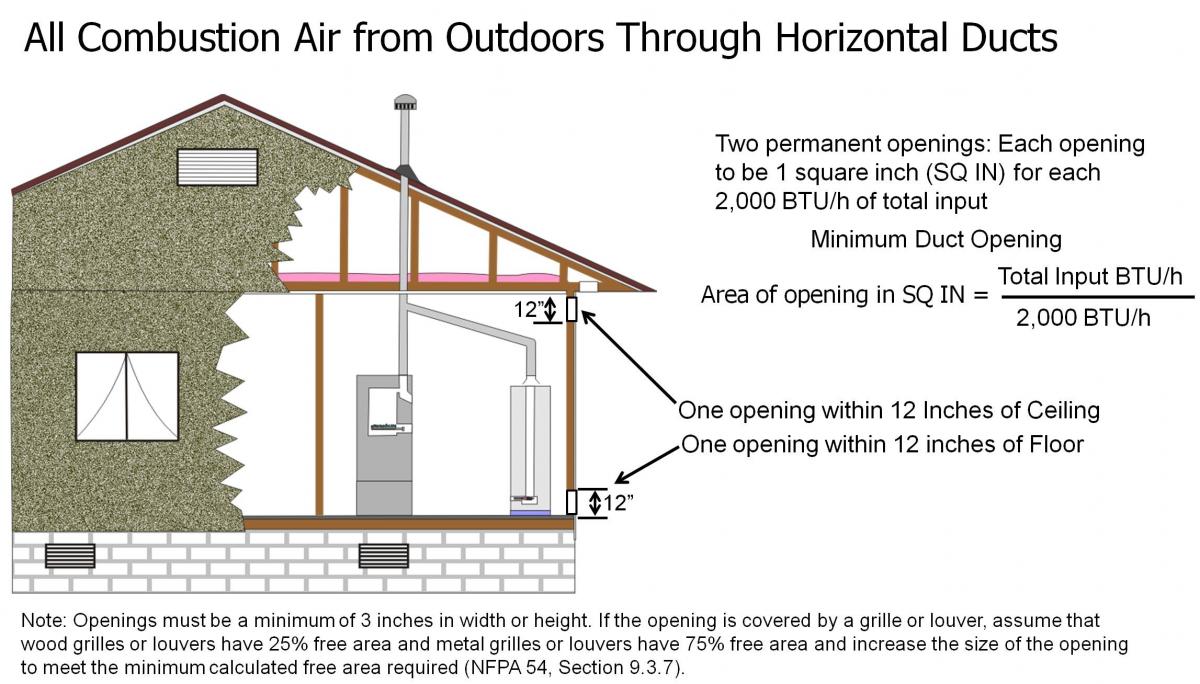
Option 3. Combustion air horizontal ducts through exterior wall – With this option shown in Figure 3, both openings are through an exterior wall, with one opening near the top of the wall and one near the bottom of the wall and total input BTU/h is divided by 2,000 BTU/h. Be sure to account for louvers, screens or grilles.
Option 4. Single duct through exterior wall – When a single combustion inlet is used in an exterior wall as shown in Figure 4, the opening should be within 12 inches of the top of the zone. The minimum net free area of the opening should be one square inch per 3,000 Btu/h of the total input of all the appliances and not less than the sum of all the vent connectors in the space.
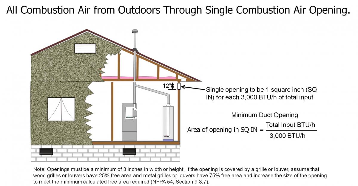
For any of these options, the openings must be a minimum of 3 inches in width or height. If the opening is covered with a grille or louver, you must compensate for the area covered by the grille. Use the manufacturer’s labeled free area when provided or, if unlabeled, assume that wood grilles or louvers have 25% free area and that metal grilles or louvers have 75% free area and increase the size of the opening to meet the minimum calculated free area required (NFPA 54, Section 9.3.7).
Option 5. Combustion air horizontal ducts through interior wall (not recommended) – Although this option is not recommended, this situation may be encountered in some older homes or retrofit projects. If this method is used, it is strongly recommended that the contractor refer to a document titled “Measure Guideline: Combustion Safety for Natural Draft Appliances Using Indoor Air.” Combustion dilution air can also be taken from the main building volume or CAZ, if adequate room volume exists, not counting rooms with closable doors.
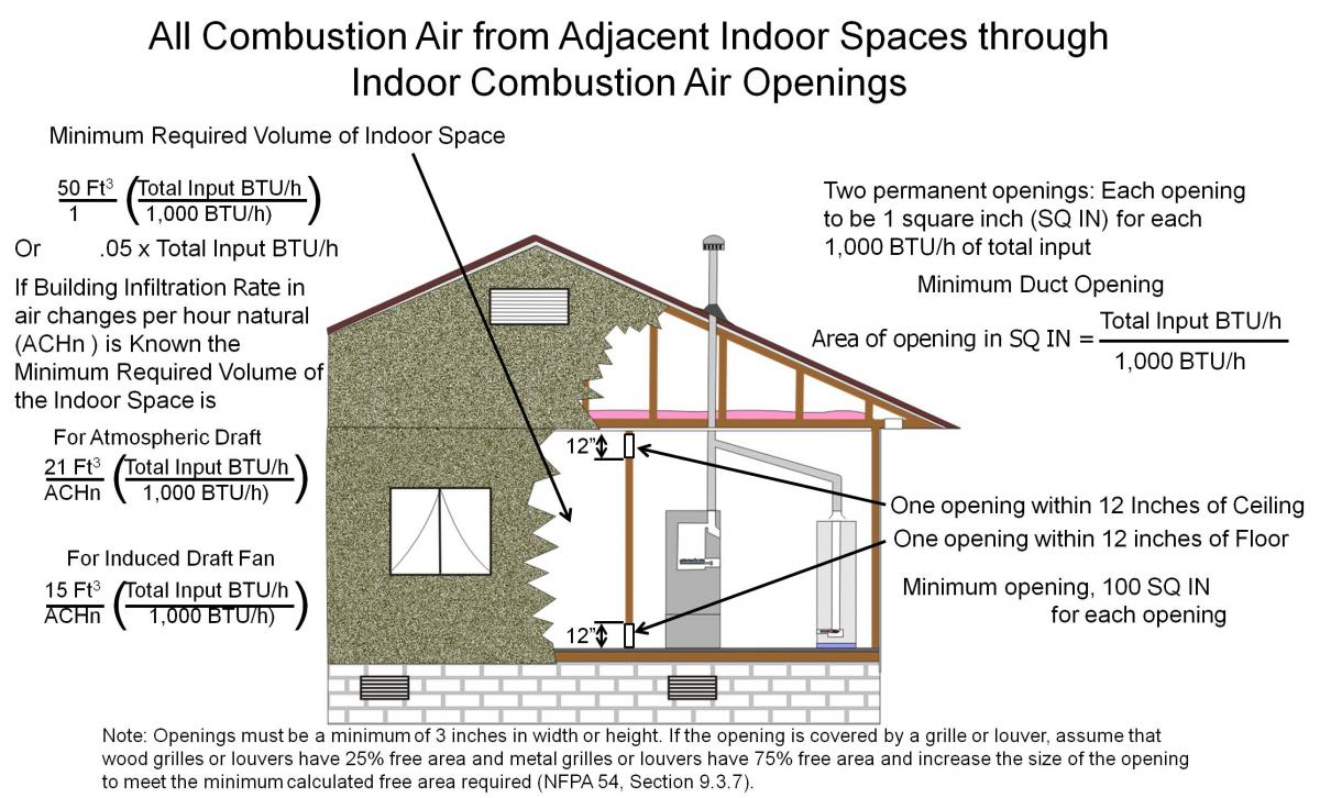
The formula to calculate the required room volume for combustion dilution air is:
(the total input BTU/H of all Category I appliances in the CAZ) X (0.05)
For example, the CAZ in Figure 1 has a Category I, 60,000-BTUH input furnace and a 30,000-BTUH input gas water heater (also Category I), which give a net of 90,000 BTUH input, so at 50 cubic feet per 1,000 BTU/h (50/1000) this gives a multiplier of .05:
0.05 x 90,000 BTUH = 4,500 ft3
Thus the equipment requires either the CAZ to be 4,500 ft3 or for the furnace to be connected to 4,500 ft3 of building space. This would be a space about 20 ft wide by 28.125 ft long by 8 ft tall. The building volume should not include bedrooms, bathrooms, laundry rooms, or any room with a door closing it off from the main volume.
If connecting the CAZ to building space through an interior wall, two openings or ducts should be located in the wall, one duct within 12 inches of the ceiling and the second duct within 12 inches of the floor. The area of each duct opening in square inches is calculated as the total input BTUH divided by 1,000 BTUH for each duct. If the opening is covered with a grille or louver, you must compensate for the area covered by the grille. Assume that wood grilles or louvers have 25% free area and that metal grilles or louvers have 75% free area and increase the size of the opening to meet the minimum calculated free area required (NFPA 54, Section 9.3.7).
How to Test the Combustion Appliance Zone
If outdoor air is used to provide combustion air to the appliances, there are two test conditions for the combustion appliance assessment: equipment-off and equipment-on.
With the equipment off, verify that the CO level in the zone is below the alarm limit and that there is no natural gas leakage. Also verify that the vent system installation is compliant with the –NFGC, Chapter 12 for installation and Chapter 13 for sizing. As mentioned above, verify that the combustion air openings are free of blockage and meet the code requirement for net free area. Finally, inspect the appliance for visual signs of deterioration and clean or repair as needed.
For the equipment-on test, turn on the equipment and perform the following checks (note that exhaust fan testing does not apply to the zone isolation case):
- Check for successful ignition and functioning controls.
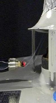
- Check that the appliance drafts correctly using a smoke pen or other device.
- Check appliance input for over-firing: clock meter or measure the size of the orifice and pressure.
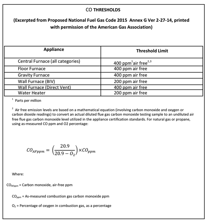
- Measure the CO level in the flue and determine that the value is not above the ANSI certification limit for that type of appliance (Table 1).
- Check safety and protective devices: pilot shut off, high temp limit, low water cutout, and temperature pressure relief.
Although this method is not recommended, if indoor air is used to provide combustion air to the appliances, follow the steps below for the combustion appliance assessment:
- Close all exterior doors, windows, and fireplace dampers. Open all interior doors. Leave open all combustion air openings to the outdoors.
- If there is a central air handler and a bedroom or separate room without a ducted return grille, close the door(s) to those rooms.
- Turn on any clothes dryers. Turn on any exhaust fans, such as range hoods and bathroom exhausts, so they will operate at maximum speed. Do not operate a summer (whole-house) exhaust fan. Close fireplace dampers.
- Place the appliance being inspected in operation. Follow the lighting instructions, if required. Adjust the thermostat so the appliance will operate continuously.
- Measure the CO level in the flue and determine that the value is not above the ANSI certification limit for that type of appliance (Table 1).
- Test for spillage at the draft hood relief opening after 5 minutes of main burner operation. Use the flame of a match or candle or smoke.
- Turn on all other fuel-gas-burning appliances within the same room so they will operate at their full inputs. Follow lighting instructions for each appliance. Circulating air blowers (if any) should be operating.
- Repeat step 6, above, on the appliance being inspected.
- If another appliance is to be inspected, shut off all appliances and return to Step 1.
- Return doors, windows, exhaust fans, fireplace dampers, and any other fuel-gas-burning appliance to their previous conditions of use.
If any combustion appliance fails the spillage test with other equipment on but passes under natural conditions with other equipment off, the cause and potential improvement is most likely with the availability of combustion air, not with the performance of the vent system. Combustion air openings to the outdoors or some other remediation may be required. If the combustion appliance fails the spillage or combustion tests under natural conditions (all exhaust fans off), a service technician should be called before proceeding.
Ensuring Success
When furnaces, boilers, and water heaters are installed within the home’s pressure boundary (i.e., within the thermal envelope), this equipment should be direct-vent/sealed-combustion equipment. ENERGY STAR permits non-direct-vented combustion appliances in Climate Zones 1, 2, and 3 if the Rater has followed Section 805 of RESNET’s Standards, encompassing ANSI/ACCA 12 QH-2014, Appendix A, Sections A3 (Carbon Monoxide Test) and A4 (Depressurization Test for the Combustion Appliance Zone), and verified that the equipment meets the limits defined within.
Region
No climate-specific information applies.
Training
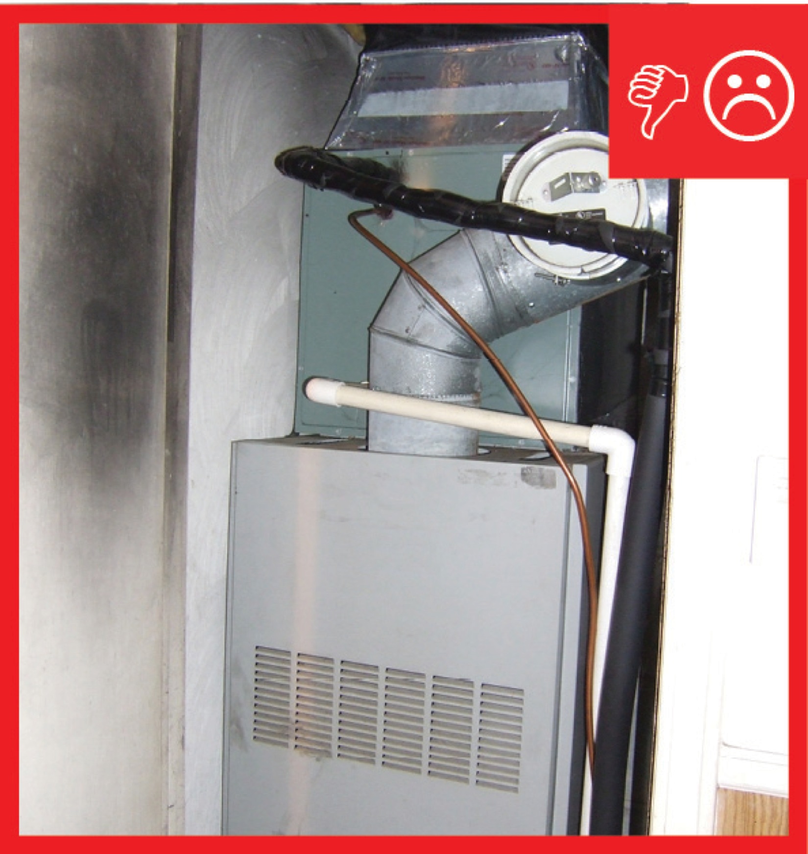
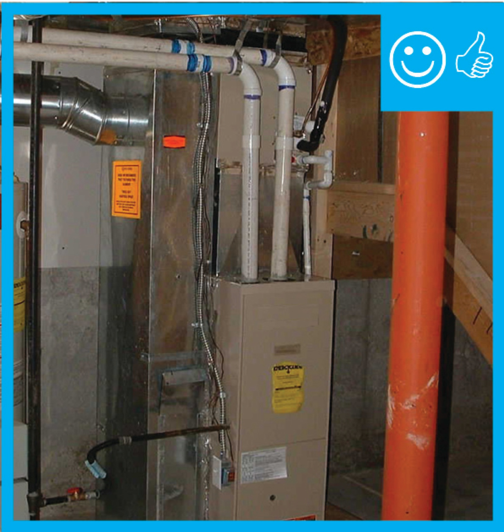
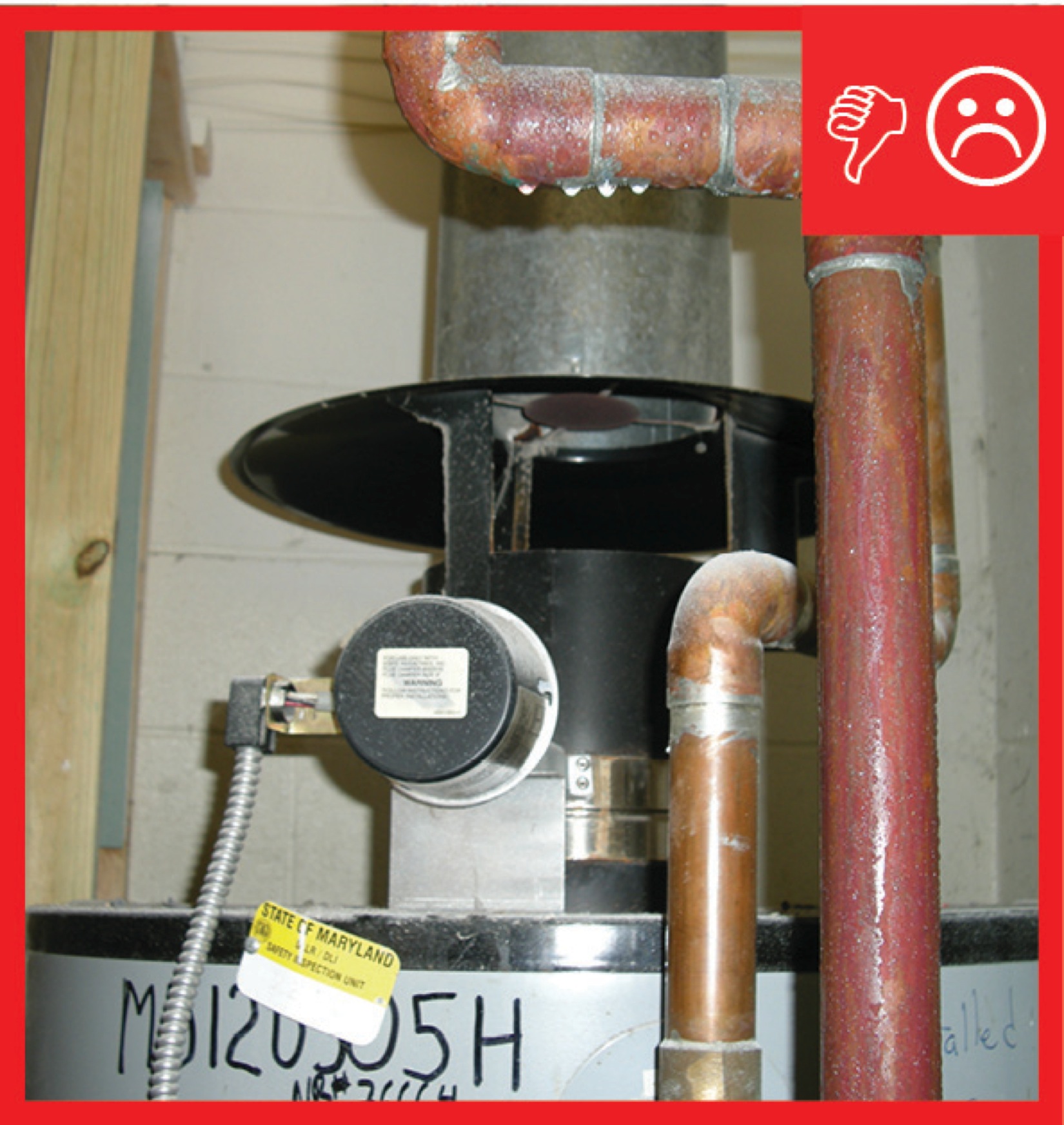
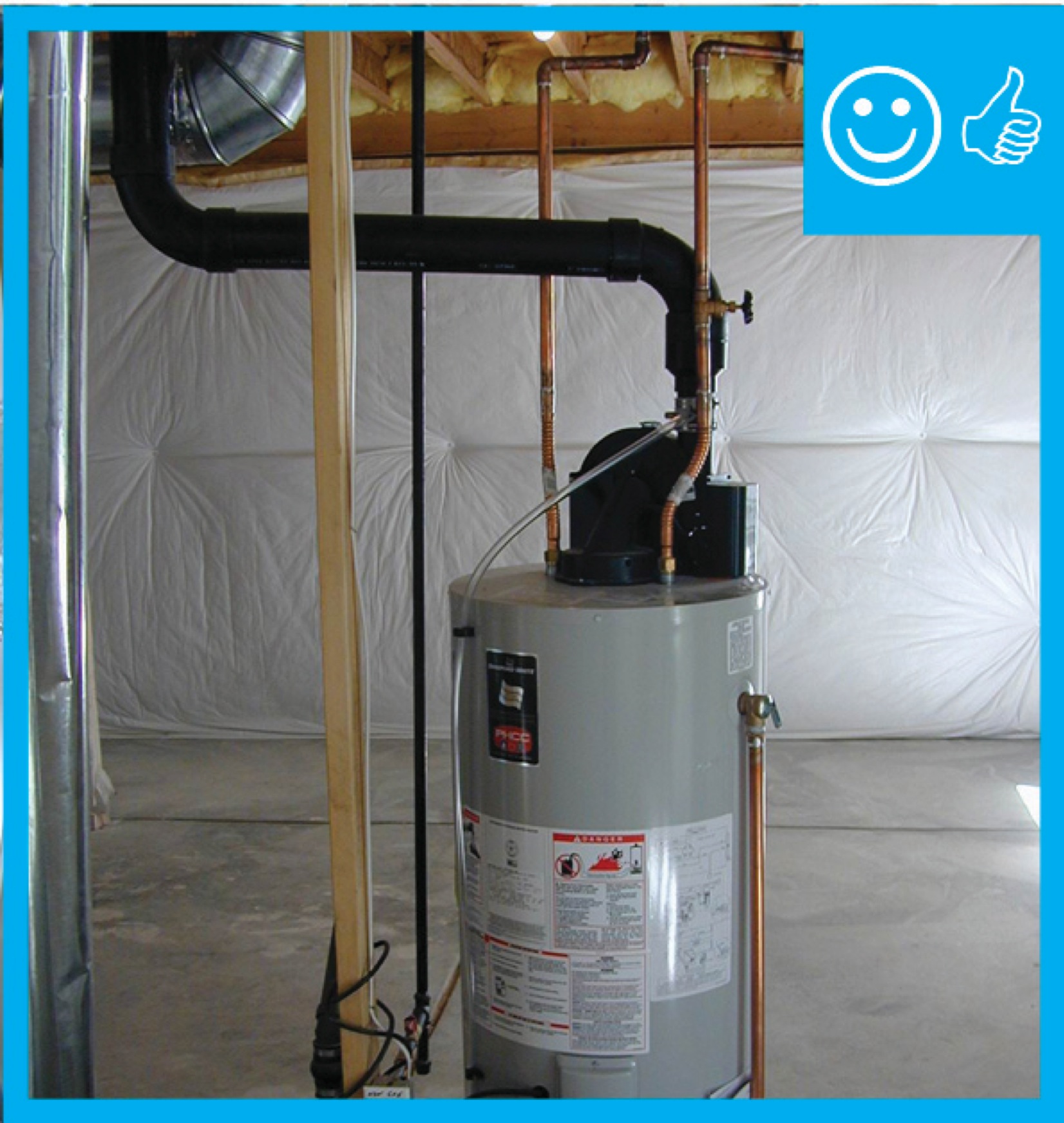
Right and Wrong Images
Source
Source
Compliance
Retrofit
When conducting renovation work in older homes, identify any combustion appliances located in the home (e.g., gas or oil-fired water heater, boiler, or furnace) and determine whether they are sealed combustion/direct vent appliances or older-model atmospheric-draft or induced-draft combustion appliances (also known as Category 1 appliances based on their designation in the National Fuel Gas Code; see the guide Direct Vent Equipment for an explanation of these categories). Any renovation work that will involve air sealing and insulating rooms, attics, basements, or crawlspaces that may contain category 1 appliances will impact how much air is available to the appliance for combustion. As part of the renovation, calculate the combustion air that will be available to the appliances and perform combustion appliance zone testing, as described in the Description tab, to help ensure that adequate amounts of makeup air will be available for safe combustion. If the home currently has atmospheric-draft or induced-draft combustion appliances, the best course of action is to replace them with more efficient and safer-direct vent combustion appliances or other non-combustion equipment.
For more information on combustion appliances, please see the assessment guide, Pre-Retrofit Assessment of Combustion Appliances.
The U.S. Department of Energy’s Standard Work Specifications has additional information on combustion appliances.
See Compliance tab.
More Info
Case Studies
References and Resources
*For non-dated media, such as websites, the date listed is the date accessed.
Contributors to this Guide
The following authors and organizations contributed to the content in this Guide.
Sales
Combustion Appliance Zone (CAZ) Test
Technical Description
Combustion safety tests are an important part of a performance check-up or a maintenance call for homes with combustion appliances that rely on gravity draft exhaust. This includes furnaces and water heaters that burn gas, propane, or oil and have open flues with a risk of combustion gas spillage when other fans are operating in the home (e.g., kitchen and bathroom fans or clothes dryers). This test helps diagnose whether these appliances are operating safely by checking if there is adequate air for all the combustion appliances present, making sure the appliances are safely exhausting emissions up the flue or chimney, and verifying that no emissions are pulled back into the home even if all of the exhaust fans in the home were operating at the same time.
Questions? Comments? Contact our webmaster.