
Air Handler Closet Retrofit

    Scope
    Scope Images
    Image
    The grille in the photo on the left brings air into a return air plenum under an air handler platform. As shown in the infrared image on the right, the plenum is not air sealed so hot attic air is being pulled into the air handler closet.
    Scope

    Create or modify an air-sealed closet to contain the air handler and the return air plenum. The return air plenum must be air sealed so that the only air that enters the plenum is air coming from the house through the filter-backed grille.

    • Form a sealed air barrier of drywall or rigid duct board (sealed on the foil side whether facing in or out) and return air grille(s).
    • Where the return plenum is formed by open framing and a plywood platform, install and seal an air barrier (drywall or duct board) to separate the return from adjacent wall cavities.
    • Provide a partial door above the return (or a solid door on the side wall) for AHU access.
    • If necessary, extend the platform to form a door sill.
    • Use a code-approved sealant, for duct board connections, preferably fiberglass mesh embedded in water-based mastic.
    • Do not leave open wall cavities in the closet or return air plenum.
    • Do not use louvered door returns.
    • Do not use a metal or frame air hander stand in a full closet return.  If a full closet return (i.e., air handler on stand in closet) is unavoidable, seal all joints, seams, and edges of the closet air barrier (e.g., drywall, floor finish, sub-floor). Install an air barrier, if necessary, to enclose wall cavities and separate the closet from the attic.
    • Complete drywall finish at the ceiling of the closet. Seal any gaps around the supply plenum.

    See the Building America Solution Center guide on Pre-Retrofit Assessment of Existing Heating and Cooling Systems for more information.

    The U.S. Department of Energy’s Standard Work Specifications has additional information on supply plenums and return ducts.

    See the Compliance Tab for related codes and standards requirements, and criteria to meet national programs such as DOE’s Zero Energy Ready Home programENERGY STAR Single-Family New Homes, and Indoor airPLUS.

    Description
    Description

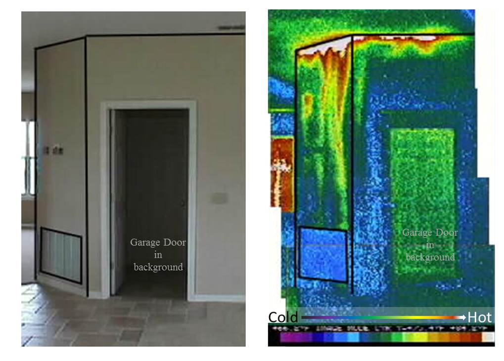
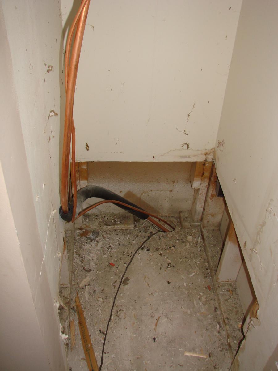
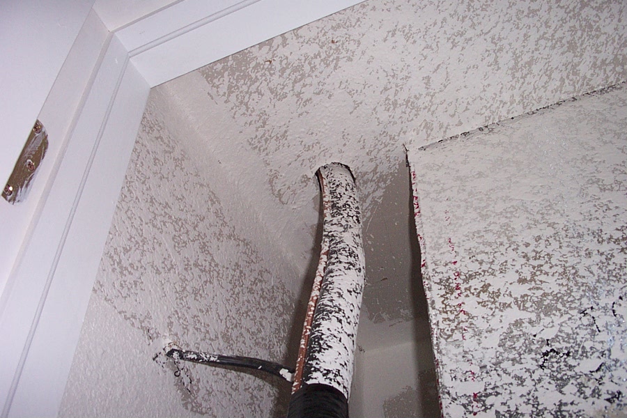
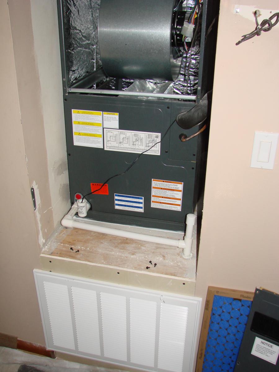
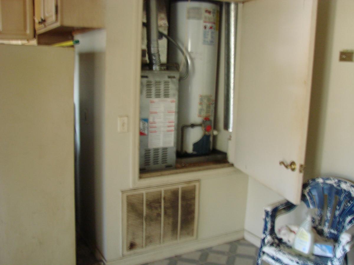
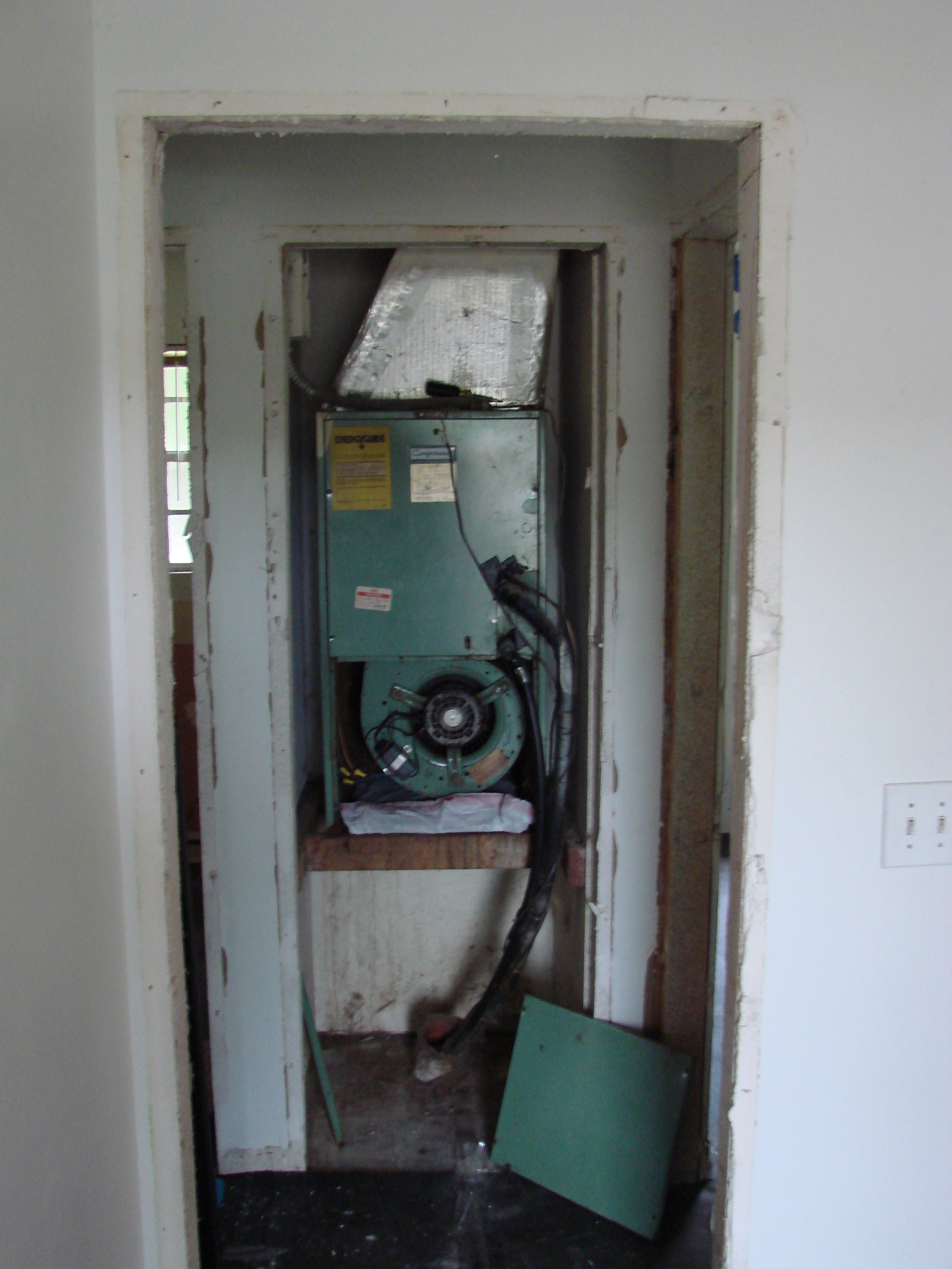
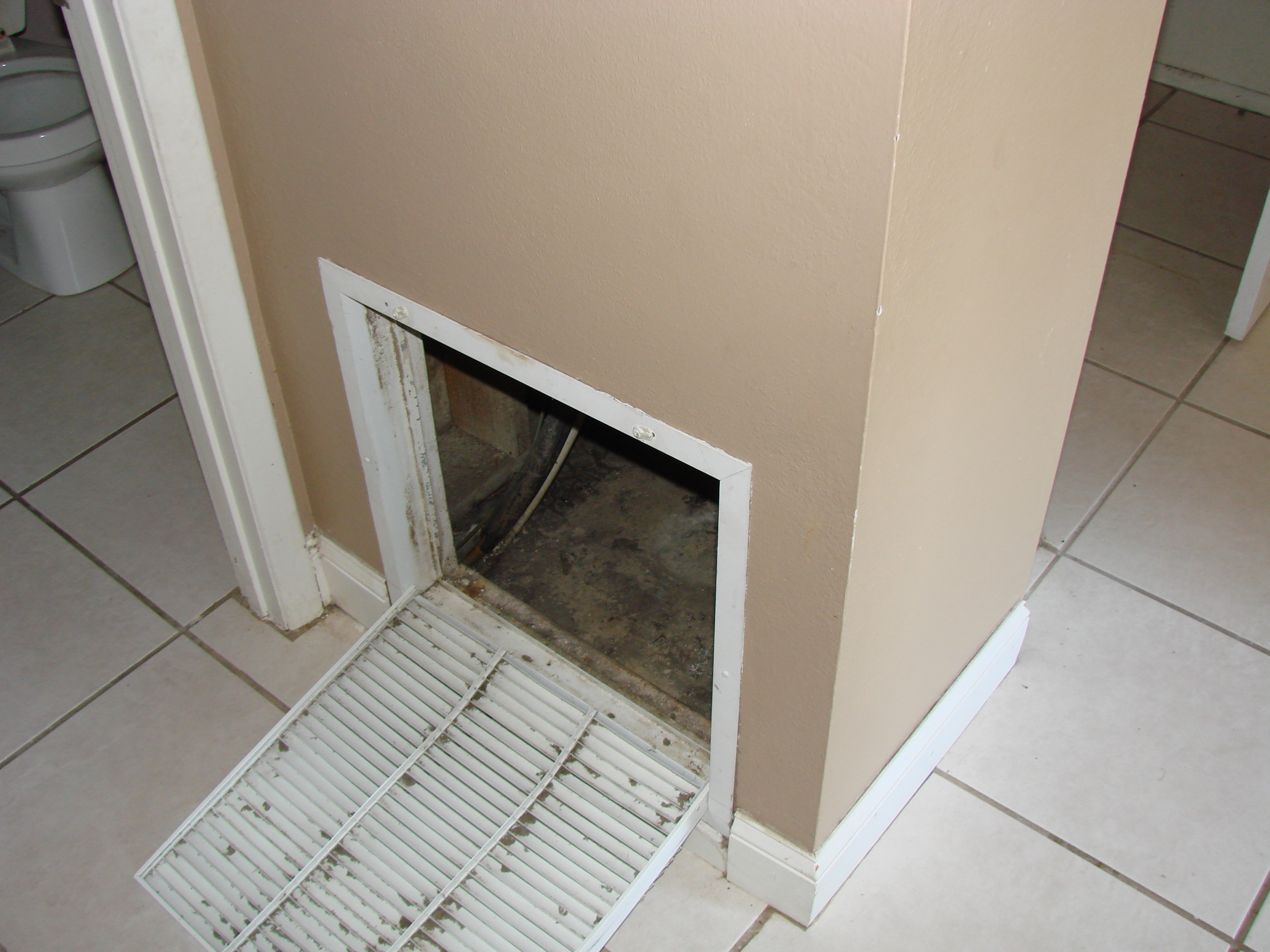
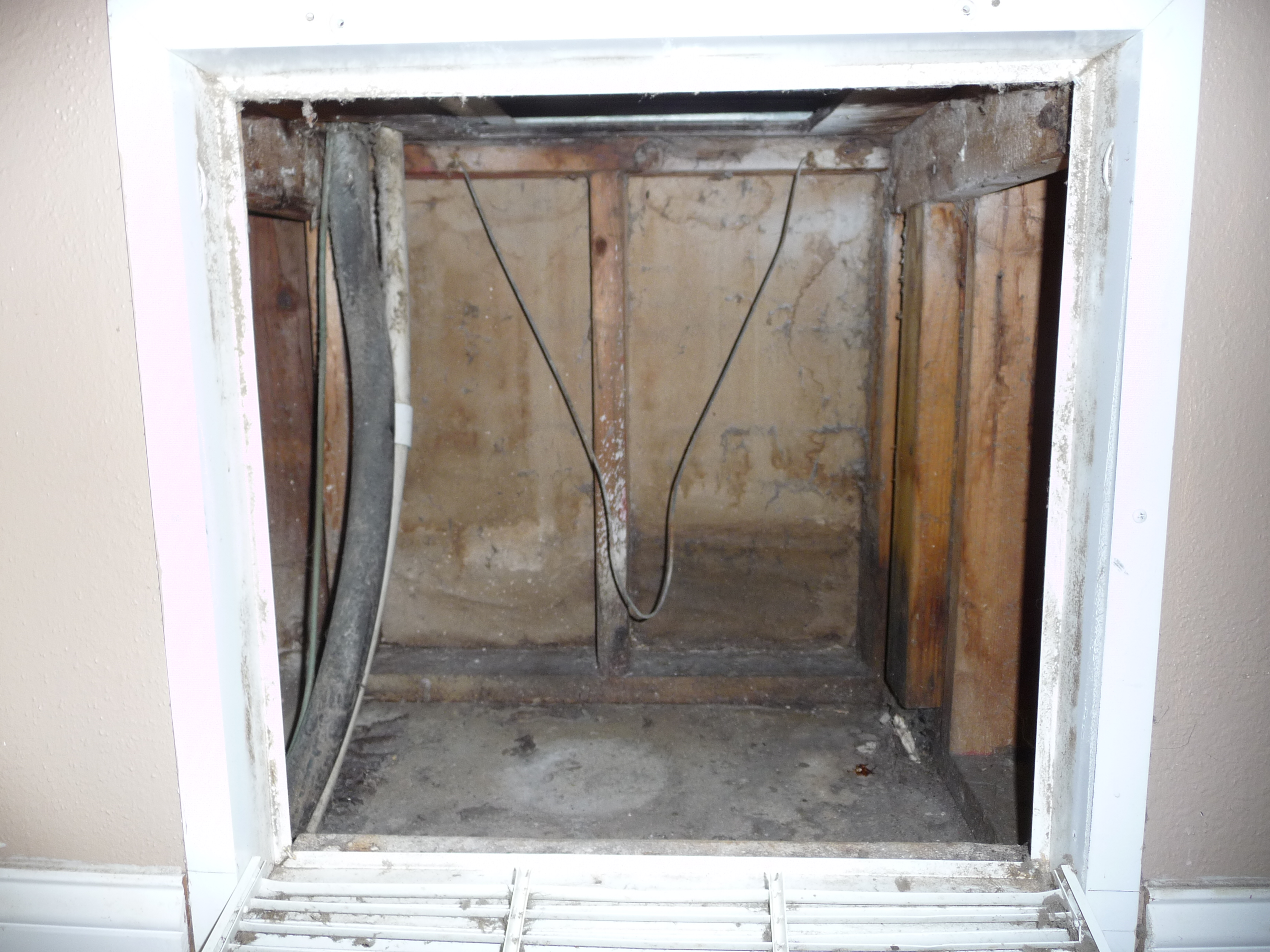
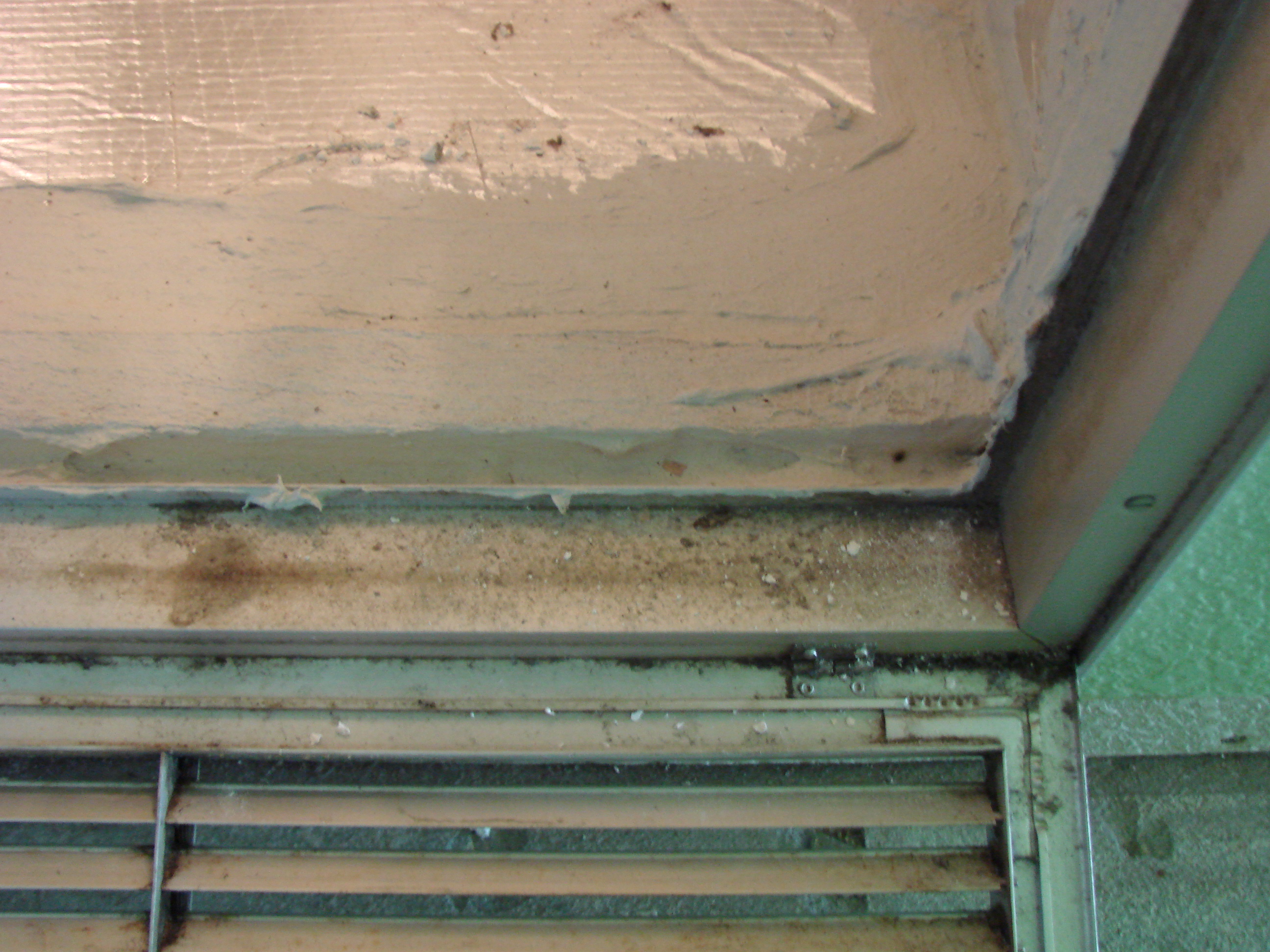
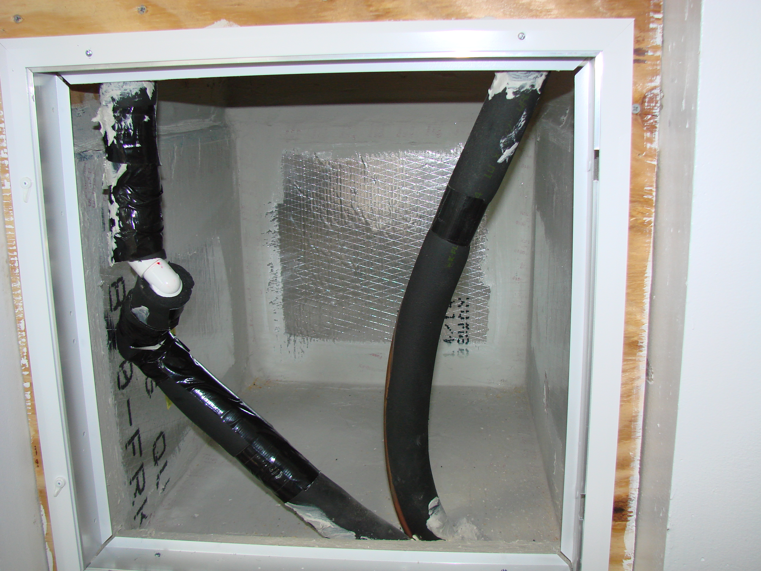
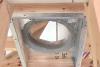
    In many homes with a central-forced air system, the air handler unit (AHU) is located in an interior closet or utility room so it appears to be isolated from the outside. However, further investigation often reveals that the AHU is connected to the outside through holes in the walls or flooring behind or beneath the AHU. The AHU is often set on a metal stand and the space beneath is used as a return air plenum, although this space may not be air sealed as a ducted return should be. The return plenum in these situations falls into a nebulous area, an interior space that is very often connected to the exterior or attic of the house through large breaches in the return plenum, the closet, or the room’s air barrier. Figure 1 shows an air handler prior to a system change-out. The open wall cavities are visible inside the return plenum.

    Open wall cavities are visible inside the return plenum beneath this air handler.
    Figure 1. Open wall cavities are visible inside the return plenum beneath this air handler (Source: Courtesy of FSEC). 


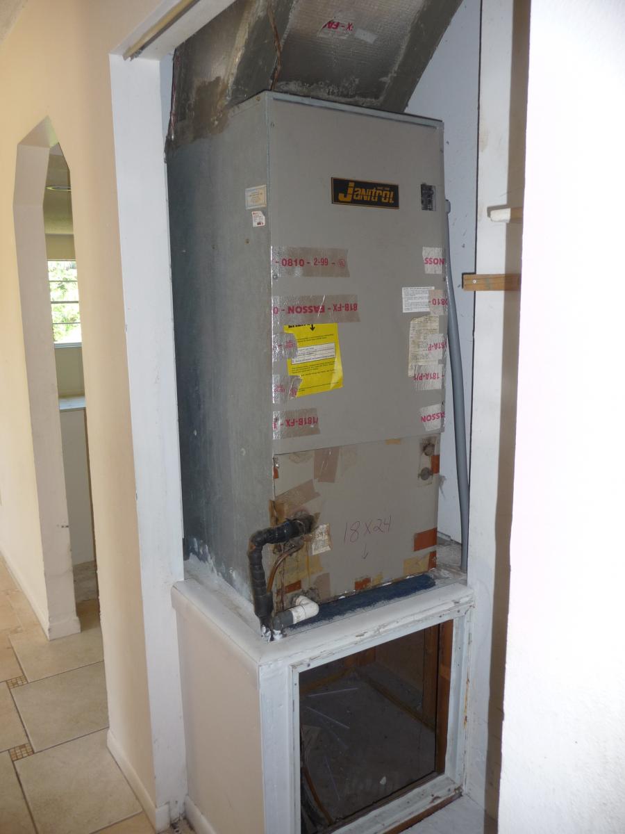
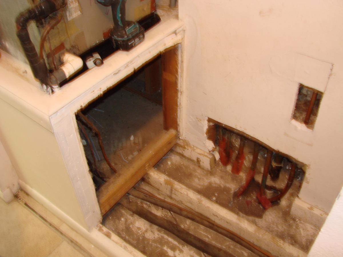
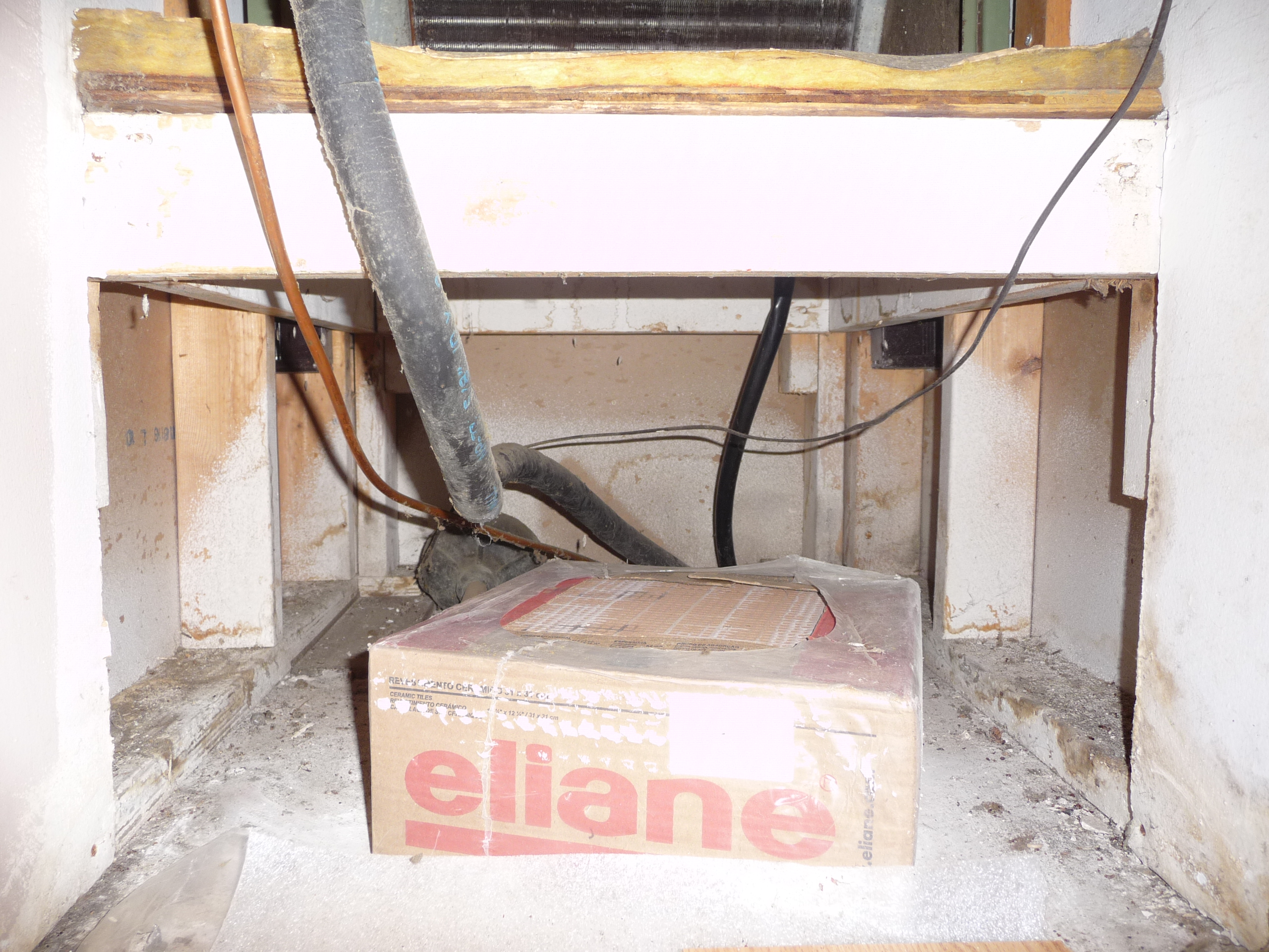
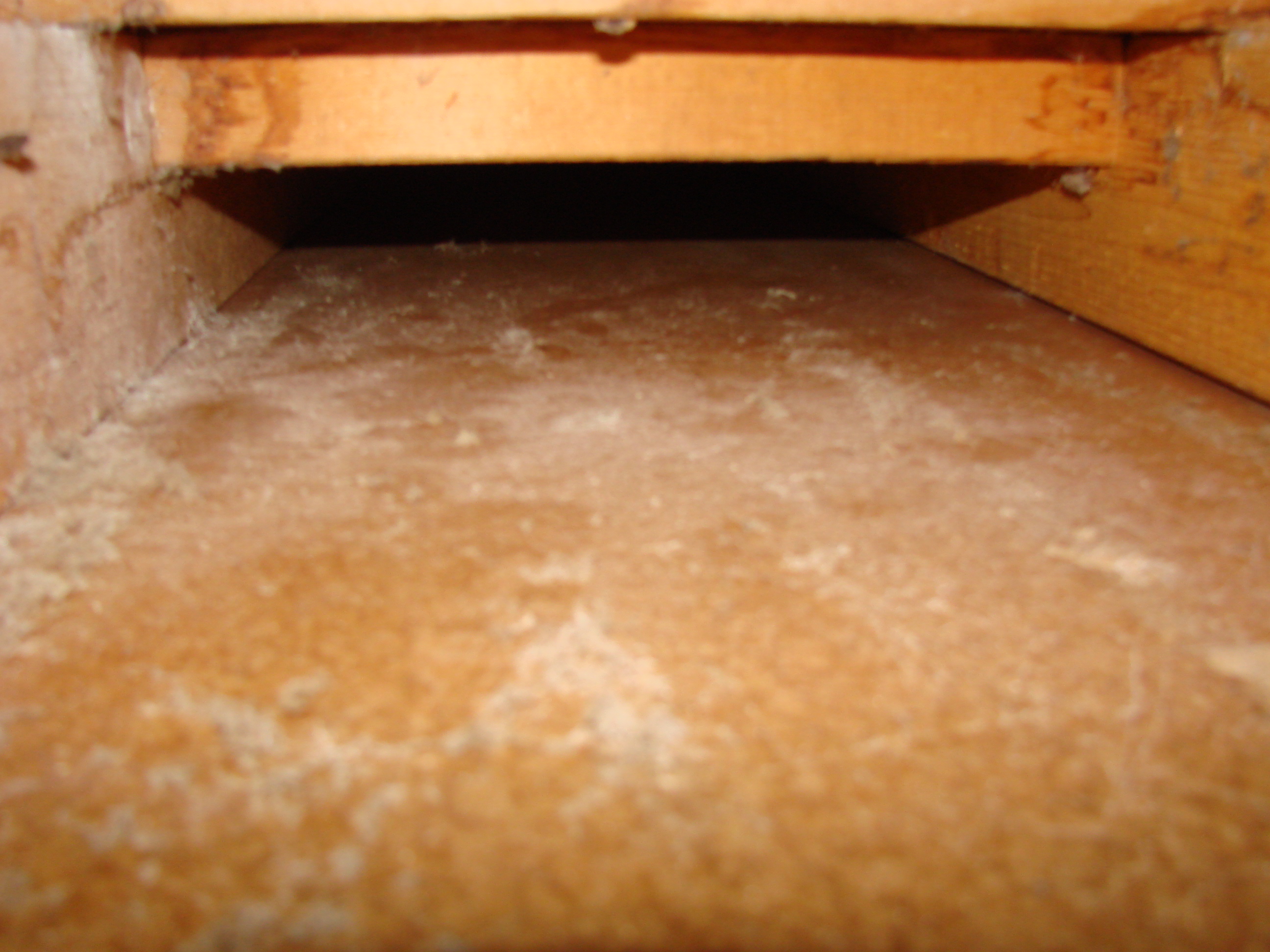
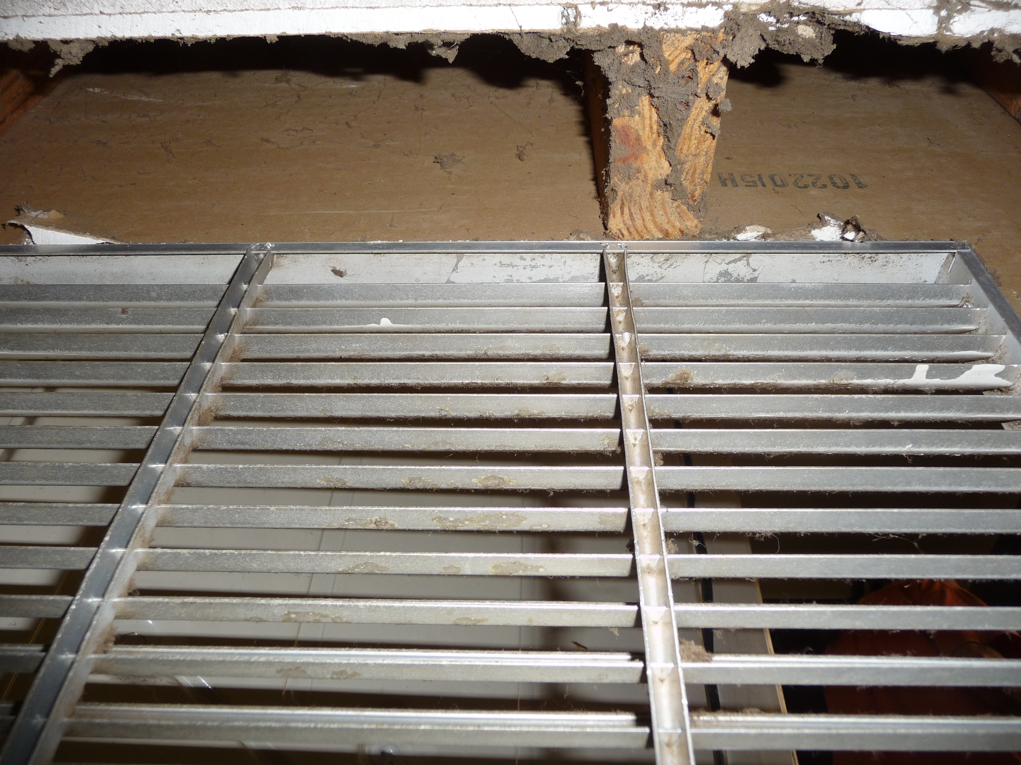
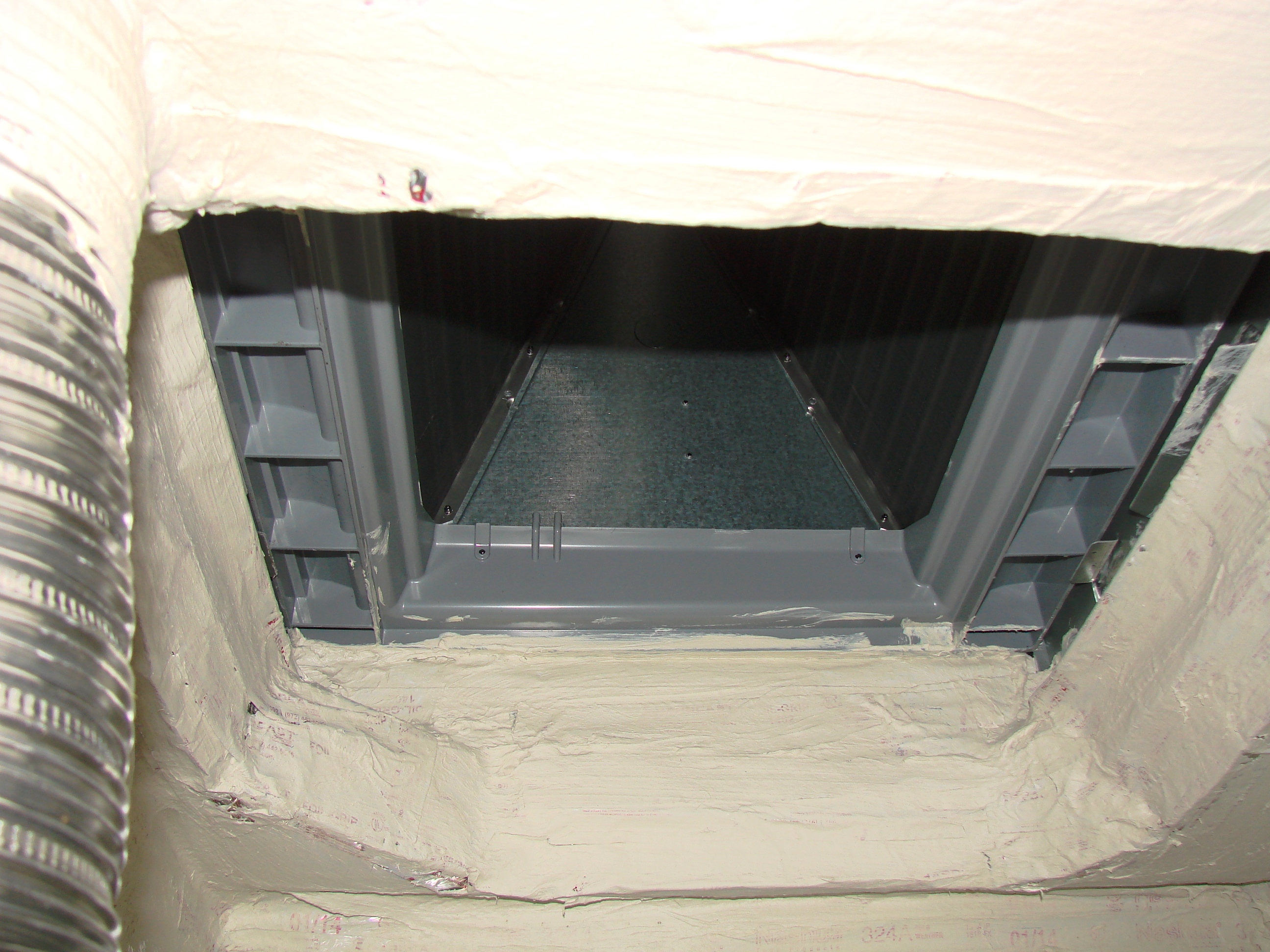
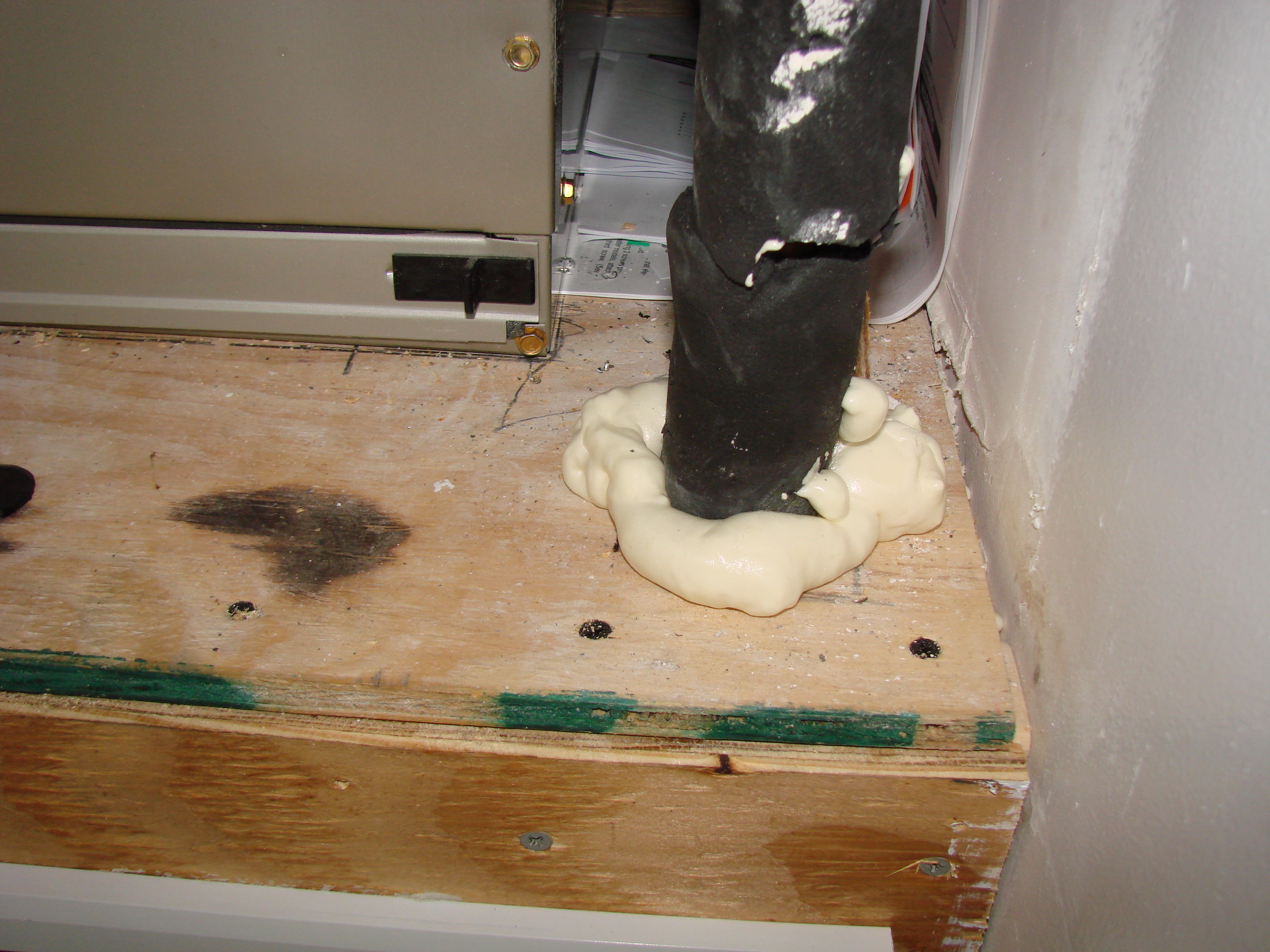
    The air handler in Figure 1 appears to be on the inside of the house; however, in Figure 2 one can see the holes in the flooring and the wall. Because of these breaches in the air barrier, the air handler is well connected to the attic, the exterior, and the slab plumbing chases (Figure 2).

    In many areas of the country, it was (and in some areas still is) customary to leave the air handler closet ceiling open to the attic to allow for combustion and make-up air if gas equipment is installed. Often, when previous retrofits have been carried out where gas equipment was replaced with all electric, the ceiling was left open to the attic. Seal this large breach in the dwelling’s air barrier.

    Plumbing access holes in the wall and flooring of the air handler closet allow outside air to be pulled into the air handler.
    Figure 2. Plumbing access holes in the wall and flooring of the air handler closet allow outside air to be pulled into the air handler (Source: Courtesy of FSEC). 


    Past and current IECC new construction codes address this potential failing, but replacement codes typically do not require any sealing to be done to these closets or utility/laundry rooms, as they are seen as interior spaces that do not require sealing.

    The only place air should be able to enter the return duct system and the furnace or air handling unit is at the return grilles (BSC 2009). It is common for air pressures in the return plenum at the air handler to equal or exceed 0.5 inches water column (125 Pascals). Air leakage problems are often worst at the HVAC furnace or air handler platform.

    How to Retrofit an Interior Air Handler Closet at Air Handler Change-out

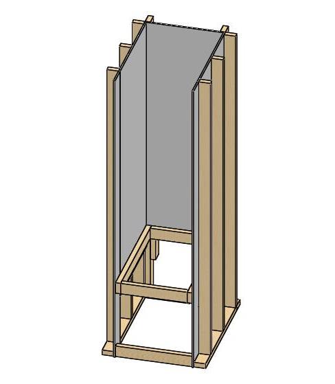
    1. Prepare the closet for repair and retrofit to seal the air handler platform (Figures 3 and 4).

    • Remove and recycle existing HVAC equipment.
    • Repair or replace existing drywall as necessary. If installing new drywall, cover the entire closet, walls, top and bottom plates, and all edges with drywall “mud.”
    Remove the old air handler and platform from the air handler closet and repair or install new drywall.
    Figure 3. Remove the old air handler and platform from the air handler closet and repair or install new drywall (Source: Courtesy of FSEC). 


    The old air handler and platform are removed from the air handler closet.
    Figure 4. The old air handler and platform are removed from the air handler closet (Source: Courtesy of FSEC). 


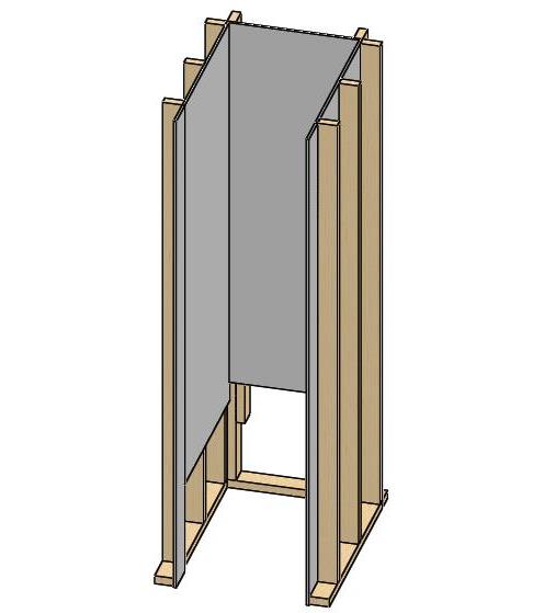
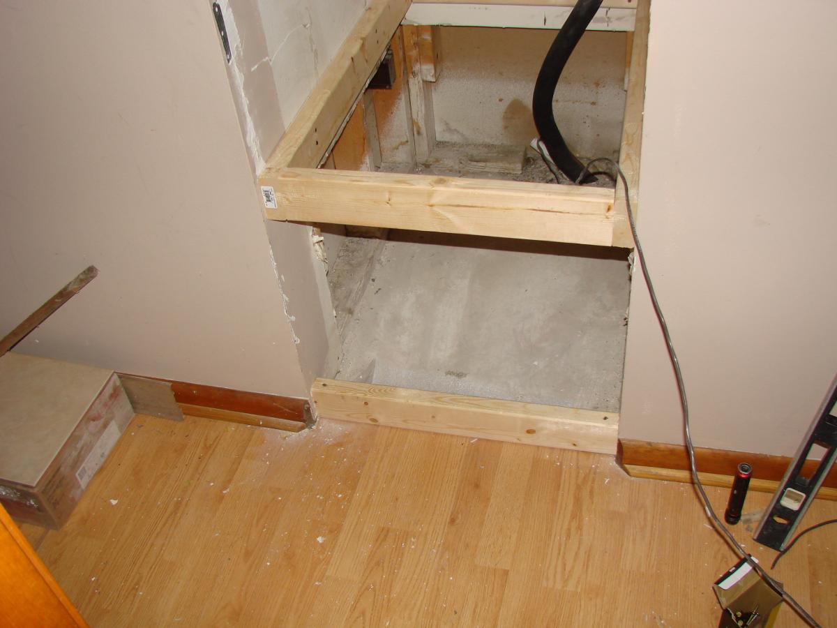
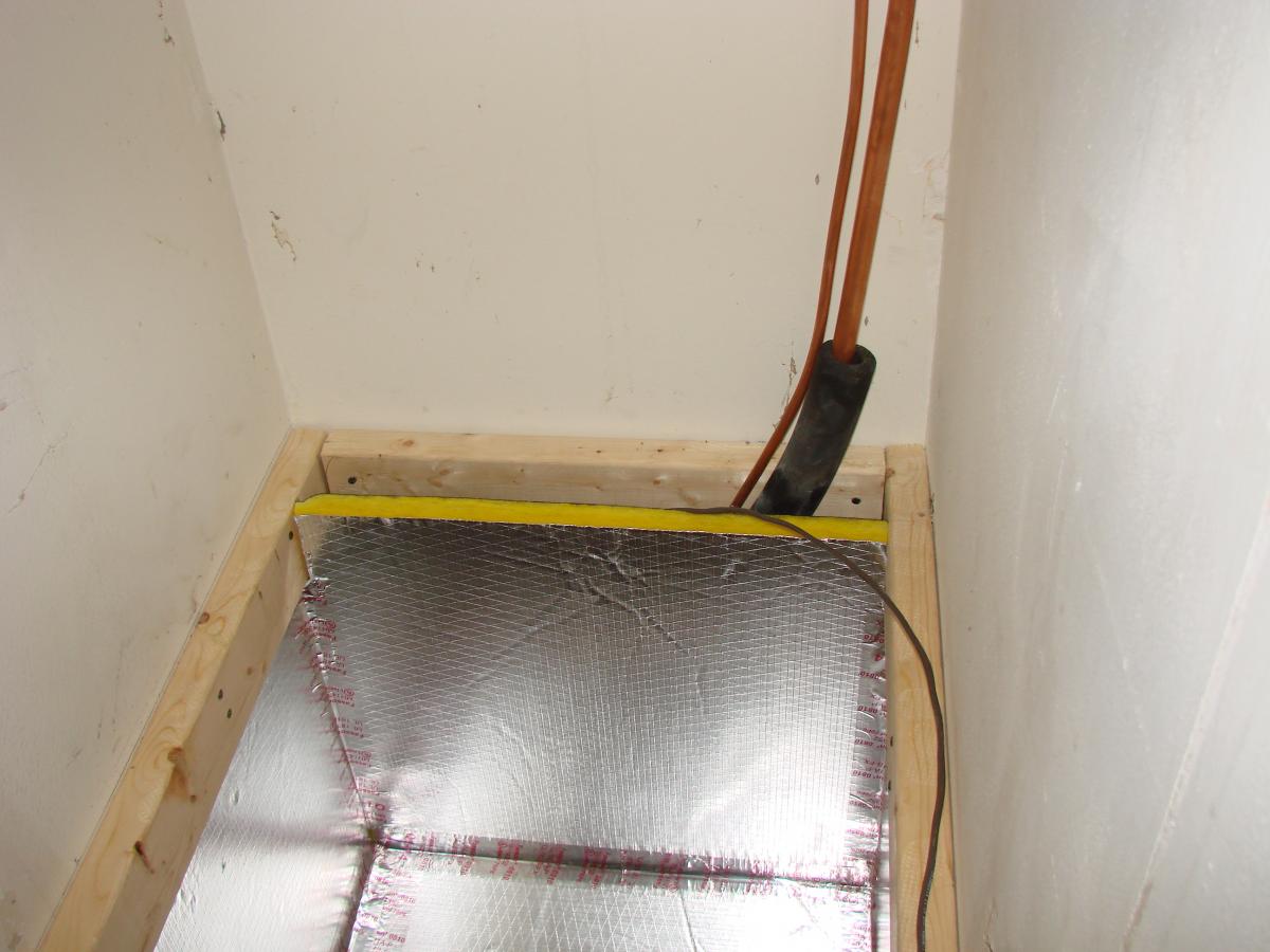
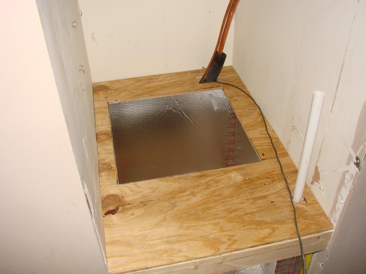
    2. Rough in refrigerant plumbing and electrical. Install framing to support the air handler platform and blocking to create a rough opening for a filter-backed return grille in the wall below the return platform (Figures 5 and 6).

    • Determine platform height prior to installation based on the return plenum sizing calculations using ACCA Manuals J and D or equivalent.
    • Install a wooden frame for the base of the air handler platform.
    • Align the front edge of the platform to facilitate final finish (drywall) of the return grille.
    Install framing for the air handler platform and filter-backed grille.
    Figure 5. Install framing for the air handler platform and filter-backed grille (Source: Courtesy of FSEC). 


    Framing is installed for the platform and filter-backed grille.
    Figure 6. Framing is installed for the platform and filter-backed grille (Source: Courtesy of FSEC). 


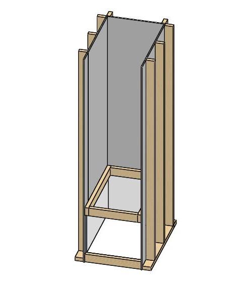
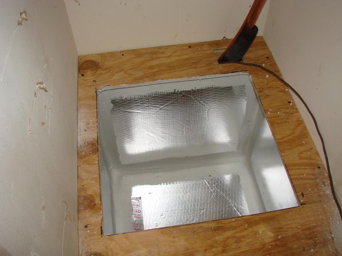
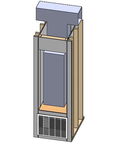
    3. Line the sides and bottom, below the platform, of the future return plenum with a code-complaint, air-impermeable material (Figures 7 and 8).

    • If the return is truly inside the house, a product with insulating properties (duct board versus drywall) is not necessary; however, HVAC contractors usually perform this work and they are equipped to work with fiberglass duct board.
    Line the sides and bottom of the return plenum with a rigid air barrier material.
    Figure 7. Line the sides and bottom of the return plenum with a rigid air barrier material (Source: Courtesy of FSEC). 


    Foil-faced foam duct board is installed to line the sides and bottom of the return plenum in the air handler closet.
    Figure 8. Foil-faced foam duct board is installed to line the sides and bottom of the return plenum in the air handler closet (Source: Courtesy of FSEC). 


    4. Install the air handler support platform (Figures 9 and 10). Fit it snuggly around any refrigerant lines or electrical connections.

    Install a plywood air handler platform on top of the new framing.
    Figure 9. Install a plywood air handler platform on top of the new framing (Source: Courtesy of FSEC). 


    The plywood platform is installed on the support framing in the air handler closet. The plywood is carefully fitted around various piping.
    Figure 10. The plywood platform is installed on the support framing in the air handler closet. The plywood is carefully fitted around various piping (Source: Courtesy of FSEC). 


    5. Seal all joints and seams with a UL-181-approved mastic (Figures 11and 12). Ensure that the edges of the grille opening are well sealed.

    All seams and joints in the return plenum are sealed with UL-181-approved mastic.
    Figure 11. All seams and joints in the return plenum are sealed with UL-181-approved mastic (Source: Courtesy of FSEC). 


    The opening around the grille at the front of the return plenum is well sealed with mastic.
    Figure 12. The opening around the grille at the front of the return plenum is well sealed with mastic (Source: Courtesy of FSEC). 


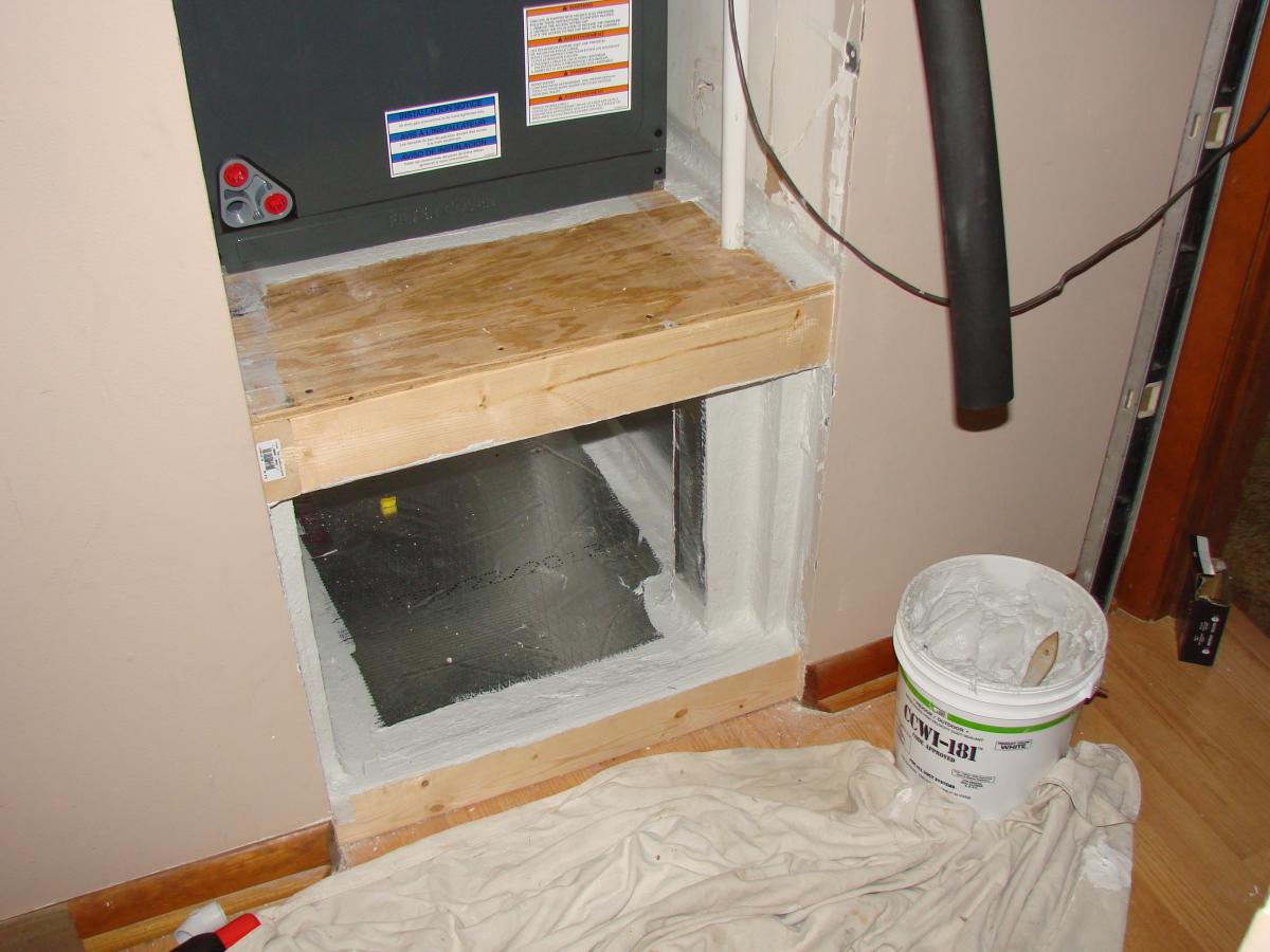
    6. Install the air handler, filter-backed grille, and supply plenum connection (Figures 13, 14, and 15). Seal the joint between the air handler and the platform. Air seal the ceiling of the closet around the supply plenum. If combustion and make-up air are required, provide it via a local code-approved installation.

    The air handler, supply plenum, and filter-backed grille over the return air plenum have been installed.
    Figure 13. The air handler, supply plenum, and filter-backed grille over the return air plenum have been installed (Source: Courtesy of FSEC). 


    The air handler closet ceiling is sealed with mudded drywall.
    Figure 14. The air handler closet ceiling is sealed with mudded drywall (Source: Courtesy of FSEC). 


    The filter-backed grille is installed in front of the return air plenum. Ensure that there is a good seal between the grille and the material used to seal the return plenum.
    Figure 15. The filter-backed grille is installed in front of the return air plenum. Ensure that there is a good seal between the grille and the material used to seal the return plenum (Source: Courtesy of FSEC). 


    7.  At finish mechanical:

    • Ensure that all four edges of the metal grille frame are sealed to the drywall and return plenum air barrier (e.g., duct board or drywall).
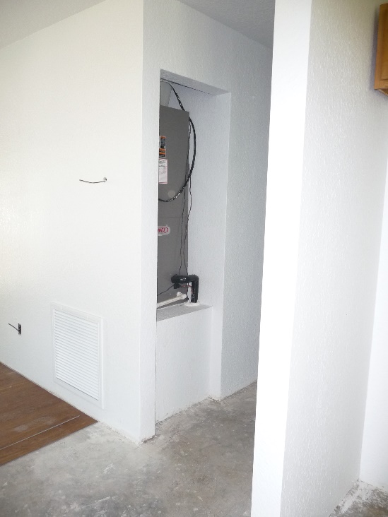
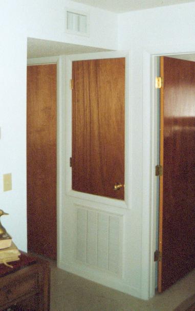
    • Provide a threshold and install a partial door above the support platform (Figure 16, image from a different house) or a full door on a side wall (Figure 17, image from a different house) to facilitate air handler access.
    A door jamb and partial door are installed on the air handler closet.
    Figure 16. A door jamb and partial door are installed on the air handler closet (Source: Courtesy of FSEC). 


    Air handler closet with side entrance return prior to door installation.
    Figure 17. Air handler closet with side entrance return prior to door installation (Source: Courtesy of FSEC). 


    Success
    Ensuring Success

    Great care must be exercised when encountering naturally aspirated gas appliances inside of the conditioned space (Figure 1). Any changes made to the pressure dynamics of the house can lead to serious and potentially fatal consequences. Work with a home professional certified by the Building Performance Institute (BPI) or Residential Energy Services Network (RESNET) in combustion safety testing to evaluate and devise a combustion safety plan to prevent accidental back drafting of exhaust fumes into the conditioned space before, during, and after renovation. Tests should be conducted to assess air pressure conditions in the combustion air zone where the furnace and/or water heater are located and air pressure differences between the combustion air zone and the occupied areas of the home.

    For gas appliances, both new installations and current equipment intended to remain in place post retrofit, ensure specifications, implementation, and installation details are in compliance with 2009 International Fuel Gas Code, Chapter 3, Section 304 for indoor and outdoor combustion air and make-up air. Add permanent openings to the building as needed for compliance as specified in Section 304.6.

    Consider conducting a standard RESNET duct airtightness assessment to determine if the return plenum is sealed. RESNET 2016.

    This closet is much too small to provide combustion and make-up air for the naturally aspirated gas furnace and water heater.
    Figure 1. This closet is much too small to provide combustion and make-up air for the naturally aspirated gas furnace and water heater. A retrofit is needed to ensure safe indoor air quality. (Source: FSEC)


    Climate
    Climate

    Applicable to all climates. No climate-specific information applies.

    Training
    Right and Wrong Images
    Image
    Wrong: The door and filter were removed, allowing unfiltered air to enter the air handler leading to premature failure of the system due to dirt accumulation.
    Wrong: The door and filter were removed, allowing unfiltered air to enter the air handler leading to premature failure of the system due to dirt accumulation.
    Image
    Wrong: The return plenum is not air sealed to separate it from the wall cavities and it should not be used for storage
    Wrong: The return plenum is not air sealed to separate it from the wall cavities and it should not be used for storage
    Image
    Wrong: Open wall cavities in the un-air-sealed return plenum connect the plenum to attic spaces
    Wrong: Open wall cavities in the un-air-sealed return plenum connect the plenum to attic spaces
    Image
    Wrong: This return air plenum is not lined and air sealed
    Wrong: This return air plenum is not lined and air sealed
    Image
    Wrong: This wall cavity is open to the attic allowing unconditioned, attic air to enter the HVAC system, bypassing the filter, and degrading system life and performance
    Wrong: This wall cavity is open to the attic allowing unconditioned, attic air to enter the HVAC system, bypassing the filter, and degrading system life and performance
    Image
    Wrong: open wall cavity connected to this return air plenum is allowing cellulose attic insulation to be pulled into the furnace
    Wrong: open wall cavity connected to this return air plenum is allowing cellulose attic insulation to be pulled into the furnace
    Image
    Right: The plenum liner is well sealed to the filter-backed grille
    Right: The plenum liner is well sealed to the filter-backed grille
    Image
    Right: The bottom of the air handler cabinet is well sealed to the return platform
    Right: The bottom of the air handler cabinet is well sealed to the return platform
    Image
    Right: Refrigerant piping is sealed where it exits the return plenum
    Right: Refrigerant piping is sealed where it exits the return plenum
    Image
    Right: Use mastic to air seal the return air plenum and to seal around refrigerant lines coming from the slab in the floor of the return
    Right: Use mastic to air seal the return air plenum and to seal around refrigerant lines coming from the slab in the floor of the return
    Image
    Right: Air seal all seams in the return air plenum before installing a new air handler
    Right: Air seal all seams in the return air plenum before installing a new air handler
    Image
    Right: A well-constructed air handler closet
    Right: A well-constructed air handler closet
    Videos
    Compliance

    Compliance

    The Compliance tab contains both program and code information. Code language is excerpted and summarized below. For exact code language, refer to the applicable code, which may require purchase from the publisher. While we continually update our database, links may have changed since posting. Please contact our webmaster if you find broken links.


    2009, 2012, 2015, 2018,  and 2021 International Energy Conservation Code (IECC)

    R403.3.4 (R403.3.2 in 2018, 2015 IECC and R403.2.2 in 2012, 2009 IECC) Ducts. Sealing (Mandatory).  All ducts, air handlers, filter boxes, and building cavities used as ducts should be sealed. Duct tightness should be verified by duct leakage testing (testing is not required if the air handler and all ducts are in conditioned space). Testing can be done at rough-in or when construction is complete. 

    R403.3.2.1 (R403.3.2.1 in 2015, 2018 IECC and R403.2.2.1 in 2012 IECC) Sealed air handler. The air handler should have a manufacturer’s designation showing that air leakage is no more than 2% of the design air flow rate when tested in accordance with ASHRAE 193.

    Retrofit:  2009, 2012, 2015, 2018,  and 2021 IECC

    Section R101.4.3 (in 2009 and 2012). Additions, alterations, renovations, or repairs shall conform to the provisions of this code, without requiring the unaltered portions of the existing building to comply with this code. (See code for additional requirements and exceptions.)

    Chapter 5 (in 2015, 2018, 2021). The provisions of this chapter shall control the alteration, repair, addition, and change of occupancy of existing buildings and structures.


    2009, 2012, 2015, 2018, and 2021 International Residential Code (IRC)

    M1601.4.1 Duct Installation: Joints and Seams. The joints of duct systems shall be made airtight by means of tapes, mastics, liquid sealants, gaskets, or other approved closure systems. The 2012-2021 IRC includes welds and mastic plus embedded fabric as joint seam materials and specifies that tape must be UL-181-approved.

    Retrofit:  2009, 2012, 2015, 2018,  and 2021 IRC

    Section R102.7.1 Additions, alterations, or repairs. Additions, alterations, renovations, or repairs shall conform to the provisions of this code, without requiring the unaltered portions of the existing building to comply with the requirements of this code, unless otherwise stated. (See code for additional requirements and exceptions.)

    Appendix J regulates the repair, renovation, alteration, and reconstruction of existing buildings and is intended to encourage their continued safe use.


    2012, 2015, 2018, and 2021 International Mechanical Code (IMC)

    603.9 Joints, seams and connections. Securely fasten all joints, seams, and connections with welds, gaskets, mastics, mastic plus embedded fabric, liquid sealants, or tapes that are listed and in accordance with Underwriters Laboratory: For connecting rigid duct use UL 181A products marked "181A-P” for pressure-sensitive tape, "181 A-M” for mastic, or "181 A-H” for heat-sensitive tape. For flexible ducts use UL 181B sealants marked "181B-FX” for pressure-sensitive tape or "181B-M” for mastic. The connections of ducts to the flanges of air distribution system equipment should be sealed and mechanically fastened.


    2012 Supplement to the Florida Building Code

    Energy Conservation.

    Chapter 1: Administration, 101.4.7.1.1 “Duct sealing upon equipment replacement (Mandatory).”

    At the time of the total replacement of HVAC evaporators and condensing units for residential buildings, all accessible (a minimum of 30 inches clearance) joints and seams in the air distribution system shall be inspected and sealed where needed using reinforced mastic or code approved equivalent and shall include a signed certification by the contractor that is attached to the air handler unit stipulating that this work has been accomplished.

    Exceptions:

    1. Ducts in conditioned space.

    2. Joints or seams that are already sealed with fabric and mastic.

    3. If system is tested and repaired as necessary.”

    The 2012 Supplement to the Florida Building Code, Energy Conservation added Section 101.4.7.1.1 Duct Sealing upon Equipment Replacement (Florida Building Code 2010: Energy Conservation 2011). It went into effect April 25, 2013. In January 2013 (prior to the April effective date), Florida House of Representatives Bill 269 was filed and subsequently passed and signed by the Governor in June 2013, effective July 1, 2013. It states, in part:

    “It is the intent of the Legislature that all replacement air-conditioning systems in residential applications be installed using energy-saving, quality installation procedures, including, but not limited to, equipment sizing analysis and duct inspection. Notwithstanding this section, existing heating and cooling equipment in residential applications need not meet the minimum equipment efficiencies, including system sizing and duct sealing.” (State of Florida 2013a).

    At the time of this writing, Section 101.4.7.1.1 was pre-empted by Florida law as stated in the Florida Building Commission issued Declaratory Statement 2013-92 issued in December of 2013 in response to a question submitted by a mechanical contractor:

    Question: Does HB 269 overturn the code requirements for duct sealing as stated in [101.4.7.1.1]? Is the duct sealing certification/form still required for existing residential change outs?

    Answer: “…if the duct system itself is not replaced, [House Bill] 269 overturns the code requirements for duct sealing as stated in Section [101.4.7.1.1].”

    The sealing of return plenums is well dealt with in new construction by both the 2009 and 2012 IECC.

    More

    More Info.

    Access to some references may require purchase from the publisher. While we continually update our database, links may have changed since posting. Please contact our webmaster if you find broken links.

    Case Studies
    References and Resources*
    Author(s)
    Building Science Corporation
    Organization(s)
    BSC
    Publication Date
    Description
    Brochure with details on HVAC duct air sealing.
    Author(s)
    McIlvaine,
    Sutherland,
    Martin
    Organization(s)
    BA-PIRC,
    Florida Solar Energy Center,
    FSEC
    Publication Date
    Description
    Research study examining efficiency retrofit opportunities, typical renovation practices, and pathways for achieving U.S. Department of Energy (DOE) goals for existing homes in Florida.
    Author(s)
    McIlvaine Janet E R,
    Beal David
    Organization(s)
    Florida Solar Energy Center,
    FSEC
    Publication Date
    Description
    Report describing as-found interior platform return plenums, the magnitude of their contribution to the total amount of duct leakage, and techniques and results of retrofits executed by the HVAC trade during equipment replacement.
    *For non-dated media, such as websites, the date listed is the date accessed.
    Contributors to this Guide

    The following authors and organizations contributed to the content in this Guide.

    Florida Solar Energy Center, lead for the Building America Partnership for Improved Residential Construction (BA-PIRC), a DOE Building America Research Team.

    Sales
    Building Science Measures
    Building Science-to-Sales Translator

    Ducted Returns =

    Image(s)
    Technical Description

    Comfort systems use fans to push heated and cooled air through ducts into living spaces. Air also needs a way to circulate back to the central comfort system equipment, where it again gets heated or cooled and circulated back to the living spaces. Most homes use centrally located return ducts to capture and return  air back to the central comfort system. In contrast, a comfort return system uses separate ducts in each major room to capture and deliver air back to the central comfort system.


    Sales Message
    Last Updated

    Mobile Field Kit

    The Building America Field Kit allows you to save items to your profile for review or use on-site.

    Sign Up  or  Log In

    Did you find this information helpful?

    If you have questions and/or would like a reply to this feedback, please include your e-mail address in the message.
    This question is for testing whether or not you are a human visitor and to prevent automated spam submissions.