

Scope
Install a combustion furnace in a home or apartment:
- Install the highest-performing furnace that project funding will allow.
- Install in accordance with the manufacturers’ instructions and relevant standards including ACCA Standard 5: HVAC Quality Installation Specification and the ACCA Technician's Guide for Quality Installations and ACCA Standard 9: HVAC Quality Installation Verification Protocols.
- Properly size the furnace and blower for the design heating and cooling load of the house or apartment, based on the ACCA Manual J heating and cooling load calculations and ACCA Manual S sizing guidelines.
- Design an efficient air distribution system with a compact layout in accordance with ACCA Manual D. Install ducts properly for maximum airflow and efficiency.
See the Compliance Tab for links to related codes and standards and voluntary federal energy-efficiency program requirements.
Description
Forced air furnaces are the most common heating source in America (EIA 2020). Forced air furnaces are typically fueled by natural gas, but propane and fuel oil furnaces are used for new homes in some locations where natural gas is not readily available. Oil furnaces have slightly lower efficiencies than gas furnaces.
Forced air furnaces are often configured with an add-on indoor refrigerant cooling coil installed in the air handler on the supply air side of the burner. Some hybrid systems (also sometimes referred to as “dual-fuel” systems) combine a gas furnace with a heat pump for heating and cooling.
Fully electric heating systems, such as electric furnaces, traditional split heat pumps, ductless heat pumps, and ground-source heat pumps can offer an alternative to fuel-fired furnaces.
Furnace Classifications
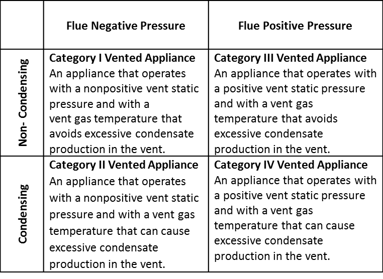
The National Fuel Gas Code (NFPA 54) categorizes furnaces based on pressures in the exhaust flue (the pipe or chimney that exhausts combustion gases to the outdoors) and flue gas temperatures (condensing or non-condensing) as shown in Table 1.
Category I Furnaces
Category I furnaces are low- to standard-efficiency, non-condensing (meaning the vent gas temperature is hot enough to avoid excess condensation in the flue), open combustion/non-direct vent (meaning they draw combustion air from the room they are in) appliances with either a natural draft or an induced draft. The flue of a Category I furnace operates at negative pressure with respect to the combustion appliance zone (CAZ), i.e., the room in which the furnace is located.
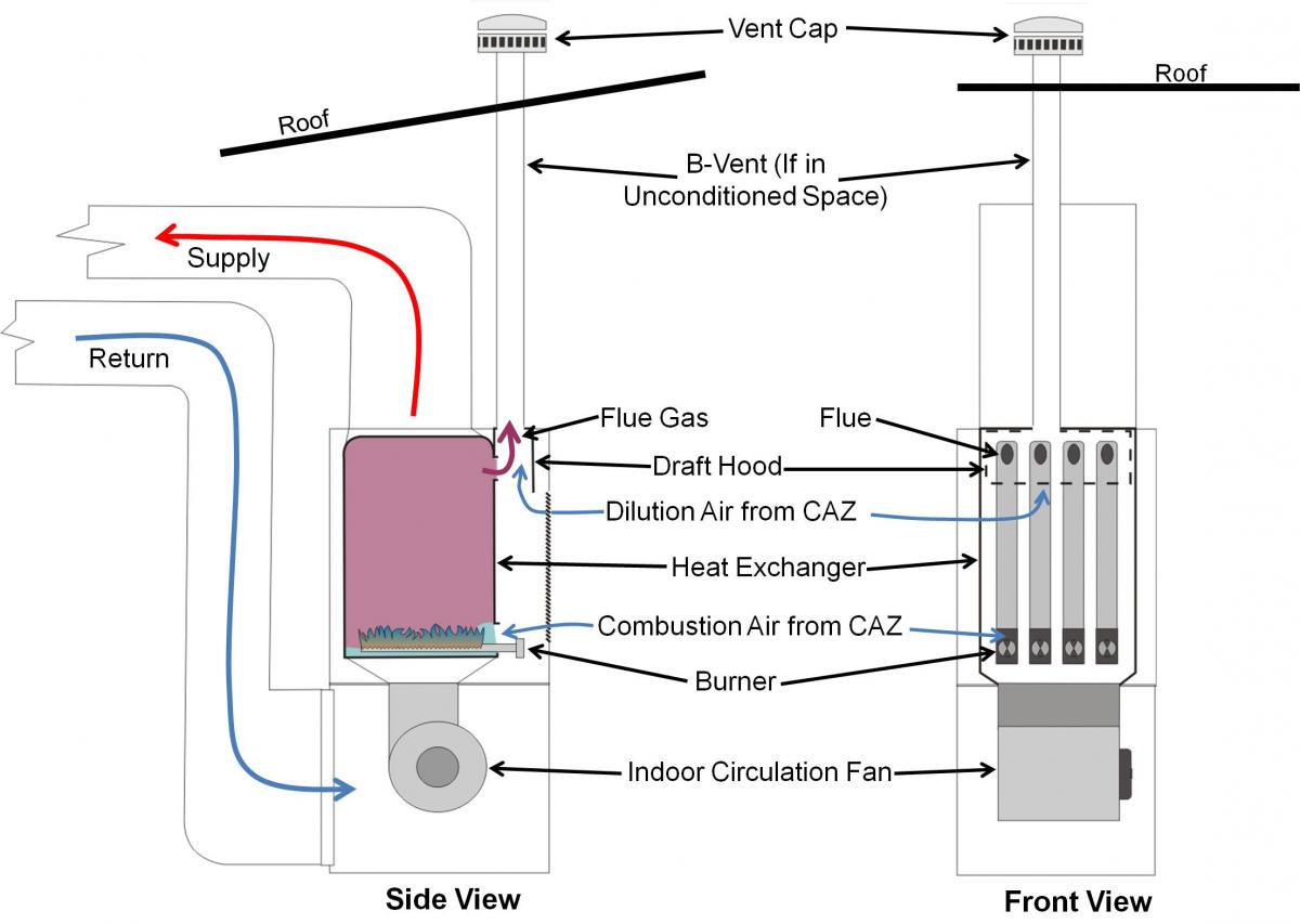
Older Category I furnaces use an open draft hood that allows dilution air to enter the vent pipe and mix with the exhaust gases (Figure 1). These older furnaces are called natural draft (or atmospheric draft) because they rely entirely on high flue temperatures to draw exhaust gases up and out of the flue due to the stack effect. Because so much of the heat goes up the flue, natural draft furnaces have very low Annual Fuel Utilization Efficiency (AFUE) ratings, usually 70% or less.
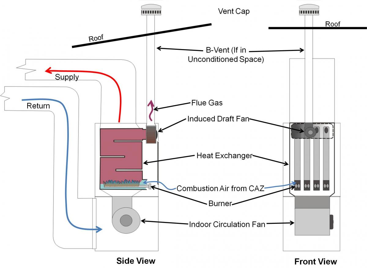
A newer type of Category 1 furnace replaced the draft hood with a small induced draft fan, which pulls air through the combustion chamber, although the furnace still relies on flue temperatures to lift the combustion gases up the flue stack (Figure 2). The induced draft fan helps to prevent backdrafting on startup and assists in getting the draft started. Category 1 induced draft furnaces typically have efficiencies of 80% to 86%, and also tend to have cleaner combustion than their older counterparts, therefore releasing less airborne pollutants.
An induced draft fan-equipped furnace is considered a mechanically drafted furnace under the International Mechanical Code (IMC). However, because it still draws combustion air from inside the home or apartment, it can still have the potential to backdraft if the CAZ becomes depressurized with respect to the flue. This could occur if multiple exhaust fans and the dryer or the fireplace are operating at the same time.
Never install a Category I furnace using the CAZ as the return air plenum; duct the return plenum to return registers in other parts of the house or apartment. The return air side of the forced air furnace should have no communication with the CAZ at all. Because Category I furnaces have an open combustion chamber, the blower fan can easily overcome the small induced-draft fan and backdraft the furnace, pulling carbon monoxide into the open return on the furnace and distributing it throughout the house or apartment via the supply ducts.
Category II Furnaces
Category II applies to some commercial furnaces but not residential furnaces. For this reason, they will not be discussed here.
Category III Furnaces
Category III furnaces are standard- to high-efficiency, non-condensing, forced-draft appliances (meaning they are equipped with a combustion fan that is located before the burner to push air through the combustion chamber and out of the flue vent). Because the draft fan is continually operating when the burner is firing, the flue stack pressure is always positive.
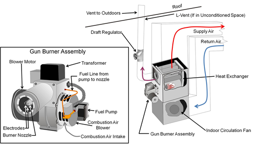
A Category III furnace vents through the wall or roof, and the flue gases exit through the flue at temperatures above 140°F. Most Category III furnaces are oil furnaces with gun type burners that force the fuel oil through a nozzle that emits the oil in an atomizing spray that mixes well with air for a more efficient burn. These oil furnaces have an efficiency range of 82% to 88%.
Category III furnaces can be installed as sealed combustion/direct-vent appliances, meaning the combustion air is supplied entirely from the outdoors through a sealed pipe. Properly installed direct-vent appliances cannot backdraft into the living space. The pipe used for the intake vent for a direct vent appliance may be separate from the pipe used for the exhaust flue, or it may be the outer circle of a concentric pipe-within-a-pipe where the inner pipe is the exhaust vent.
Although it is not recommended, Category III furnaces can also be installed as non-direct vent appliances where the combustion air is drawn from the CAZ and enters the furnace through a port on the combustion chamber, while exhaust gases vent to the outside via the single vent pipe (Figure 3). It should be noted that if Category III furnaces are installed in this manner, they have the potential to backdraft into the living space if the return air is not ducted.
Category IV Furnaces
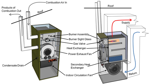
Category IV furnaces are high-efficiency, condensing, sealed combustion/direct-vent, forced-draft appliances (meaning they are equipped with a fan to pull air through the combustion chamber and push combustion byproducts out of the furnace through the exhaust flue).
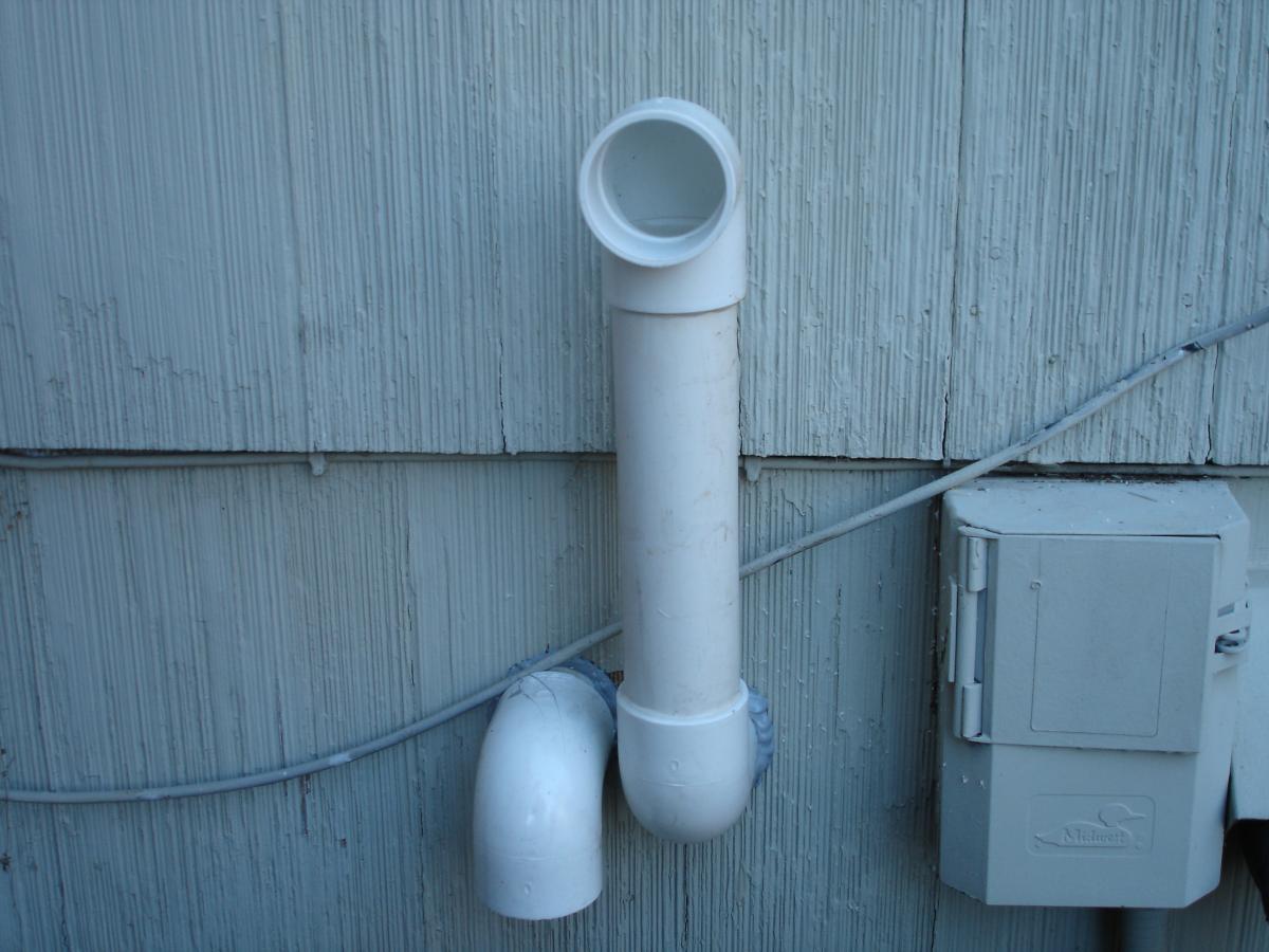
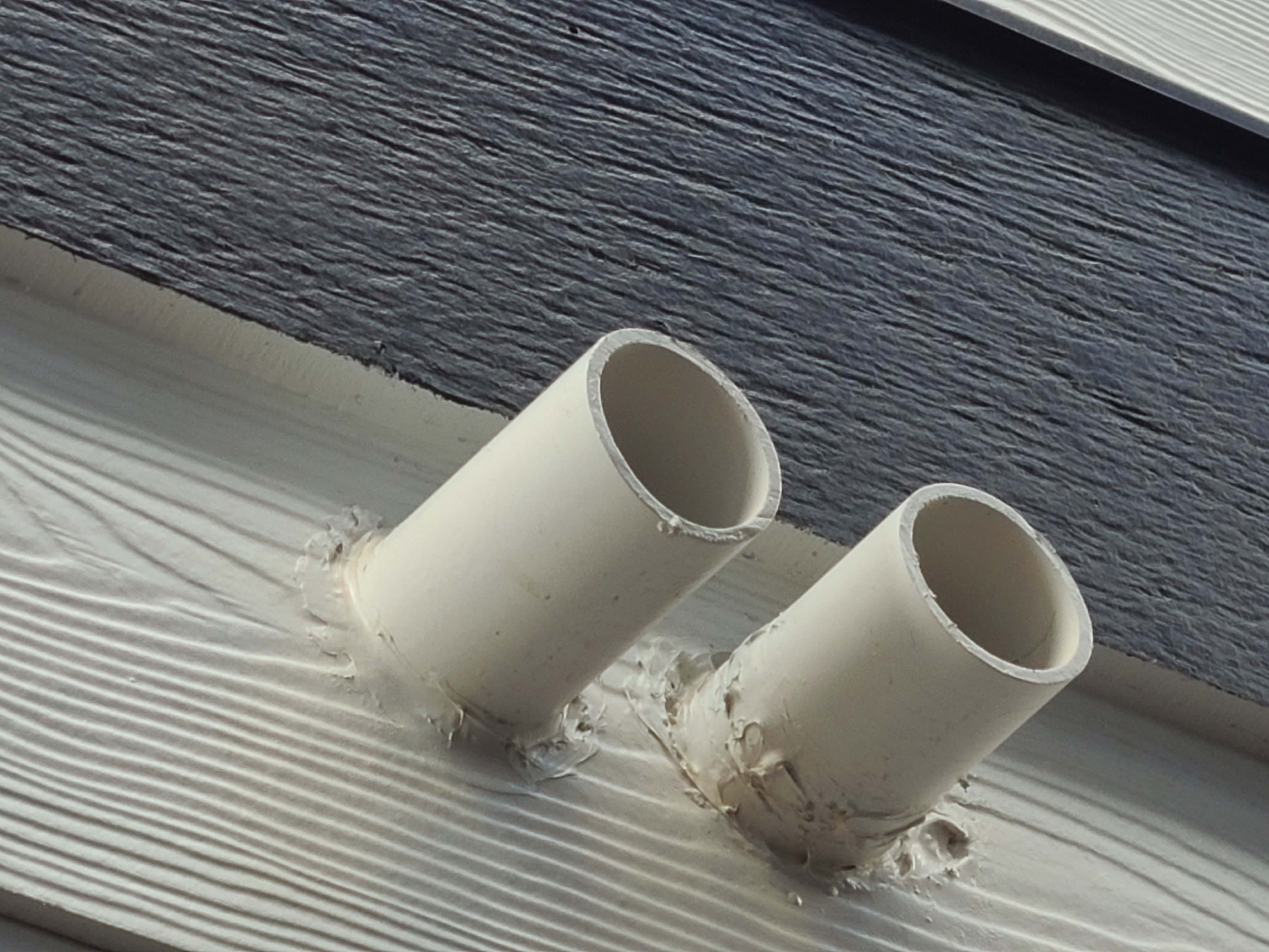
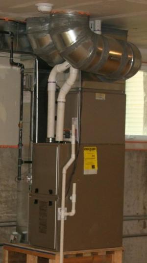
The vent pipes of Category IV furnaces are under positive pressure with respect to the outdoors. Because Category IV furnaces have two heat exchangers, more heat is extracted from combustion gases than in other furnace types. This lowers the combustion gas temperature, allowing water vapor in the gases to condense on the secondary heat exchanger. As it condenses, the water releases extra heat, enabling gas-fired Category IV furnaces to achieve efficiencies of >90% AFUE. Due to the low exhaust temperatures, water vapor can also condense inside the vent pipe, so the pipe must be designed for contact with condensate. This liquid is drained to the outside through a condensate drain. The condensate is highly acidic (pH ≤3), so local code may require that it be pretreated before disposing to the sewer. Additionally, because the exhaust gas temperature is low (under 140°F) after passing through two heat exchangers, the vent pipe for Category IV furnaces can be made of PVC (Figure 4).
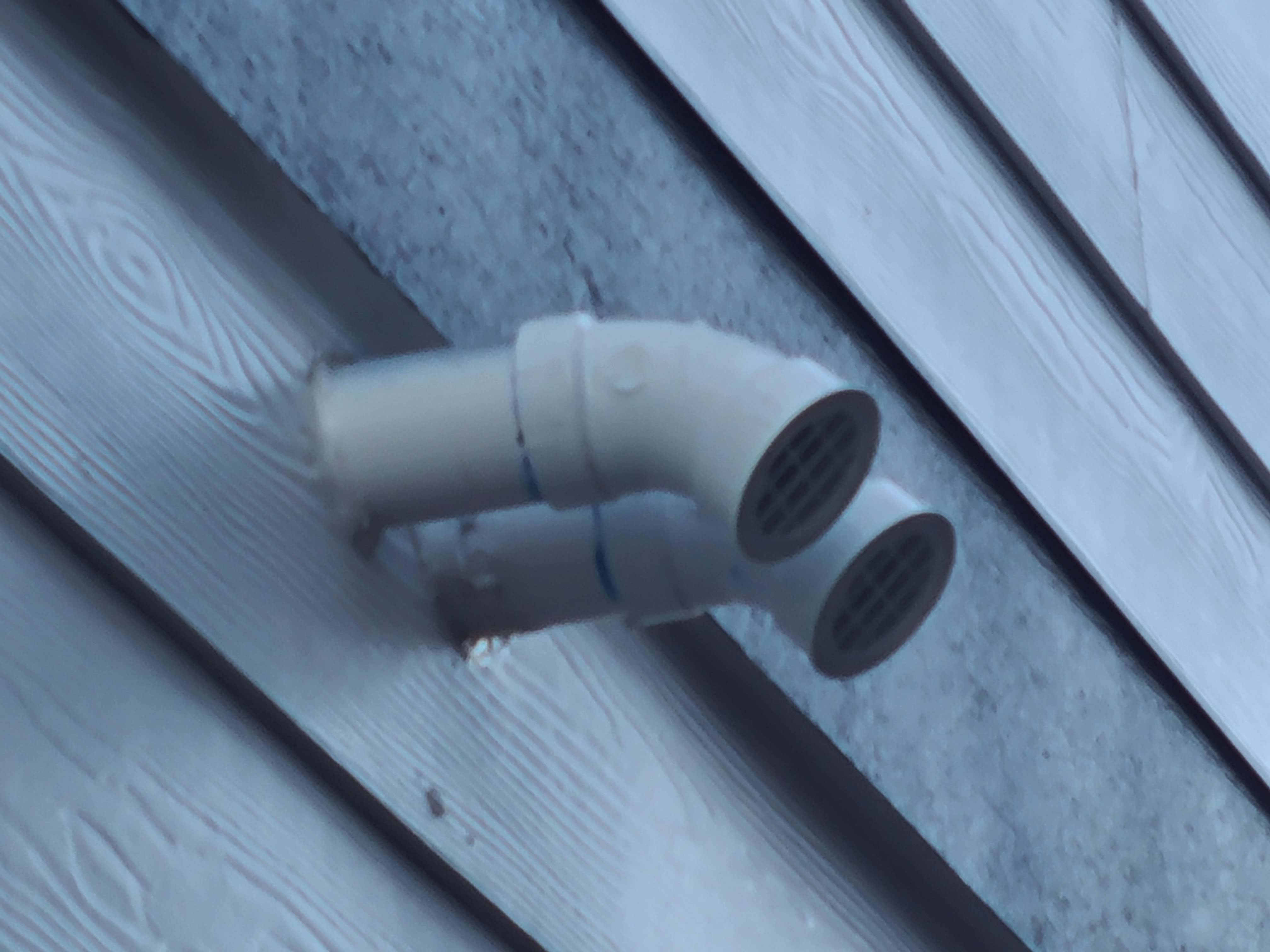
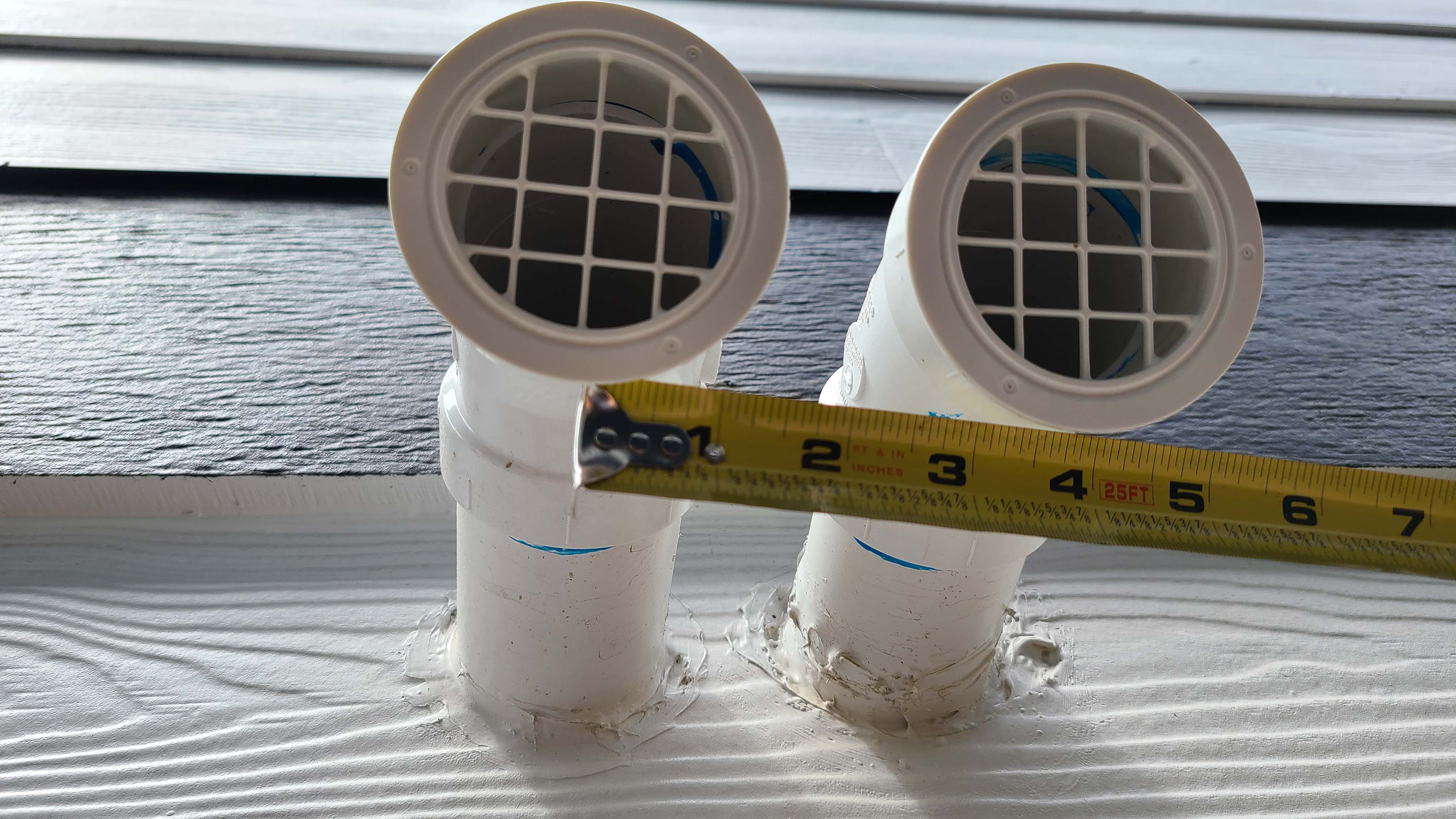
Category IV furnaces should be installed as sealed-combustion/direct vent appliances, which means their combustion chamber is sealed off from the CAZ and they draw their combustion air from outside via a second vent pipe that brings combustion air directly to the combustion chamber from the outdoors (Figure 5). Because of this, Category IV furnaces cannot backdraft into the living space. Manufacturers do not recommend installing Category IV furnaces as non-direct vent furnaces that draw their combustion air from the CAZ. Always install a second vent pipe to bring combustion air in from outside. Similar to Category III furnaces, the intake vent for a Category IV furnace can either be separate from the pipe used for the exhaust flue, or the outer circle in a concentric pipe-within-a-pipe configuration, where the inner pipe is the exhaust vent.
ENERGY STAR Single-Family New Homes, ENERGY STAR Multifamily New Construction and DOE Zero Energy Ready Home program permit naturally drafted furnaces in some circumstances. See the requirements for each program for more details. However, all ≥80% AFUE furnaces available today are induced draft fan equipped or direct-vent furnaces. When naturally drafted or induced draft furnaces are installed, a combustion safety test must be performed. See Direct Vent Equipment for more on combustion safety testing of combustion heating equipment.
See the Compliance Tab for more information on specific program requirements regarding combustion furnaces.
How to Select and Install a Furnace
- Choose the highest performing furnace that projects costs will allow, to meet the design heating load of the project. If you are participating in an energy-efficiency program, select a furnace that complies with the requirements for your climate zone, as described in the Compliance Tab.
- Install in accordance with the manufacturers’ instructions and relevant standards, including ACCA Standard 5, the ACCA Technician's Guide for Quality Installations and ACCA Standard 9.
- Select a furnace that is properly sized to meet the design heating and cooling load of the space, based on the ACCA Manual J calculations and Manual S sizing guidelines.
- Design and install an efficient duct system with a compact layout in accord with the ACCA Manual D. See the guides on duct installation, insulation, and air sealing for additional information.
- Install the furnace per the manufacturer’s instructions. A direct-vent installation where combustion air is piped directly to the furnace combustion chamber from outside is preferable. If the furnace must use the CAZ for combustion air, verify that required combustion air is provided in the CAZ and perform a combustion safety test after installation. If a Category I furnace is installed, do not use the CAZ as the return air plenum; duct the return to another room. If the combustion appliance (furnace, boiler, water heater) is a Category I appliance, verify that the minimum amount of combustion and dilution air is provided in the CAZ. For an explanation of how to calculate the combustion air needed for the CAZ, see the guide Combustion Appliance Zone (CAZ) Testing.
- For condensing furnaces, ensure that the condensate drains properly. The condensate line can be routed to an existing sewer or septic system. Ideally, this can be done with a simple gravity line, but many applications will require a condensate pump. Regardless, it is important to protect the condensate line from freezing. The condensate is fairly acidic, and some local codes require neutralizing it. Provide a secondary (emergency) drain pan constructed of durable material.
Ensuring Success
Choose a Category IV high-efficiency, sealed-combustion/direct-vent, condensing furnace whenever possible.
Install in accordance with the manufacturers’ instructions and relevant standards including ACCA Standard 5, the ACCA Technician's Guide for Quality Installations and ACCA Standard 9.
Size the furnace and ducts as described in ACCA Manual D and Manual S.
For Category I furnaces (not recommended), before installation, calculate the required combustion air for the selected furnace model and verify that the amount is provided by the CAZ.
If the furnace is a Category I furnace, a BPI- or RESNET-certified rater should perform a combustion safety test after installation.
For Category IV furnaces, ensure that the horizontal portion of the exhaust vent pipe slopes slightly toward the furnace. Ensure that the condensate line drains to a sewer or septic tank or as directed by the local jurisdiction. If the condensate drains to the outdoors, insulate the line or wrap it with heat tape to protect it from freezing. Consider pretreating the condensate to reduce its acidity. Also ensure that a drain pan is installed under the furnace as a backup measure.
Region
See the Compliance tab for climate-zone-specific combustion furnace requirements.
Warm Climates
In warm climates, central forced air systems are typically sized to the cooling load, not the heating load; thus, the furnace may be oversized for the heating load. A significantly oversized combustion furnace may continuously cycle on and off, rather than operating at steady state for long periods. Repeated short cycling is energy inefficient and can rust out the internal parts of the furnace due to the formation of condensation if the furnace repeatedly heats and cools too quickly. In warm climates, stay within ACCA Manual S oversizing limits for gas and oil furnaces. Select a furnace that combines a large blower with a smaller heating capacity. Or consider an alternative heating and cooling option such as traditional split heat pumps or ductless heat pumps.
Cold Climates
In cold climates, in addition to proper sizing, it is critical to use sealed-combustion, direct-vent, or power-vented equipment. It is also critical to make sure that the air intake and exhaust discharge vents are located sufficiently above the anticipated snow line. The intake should be sufficiently separated from the exhaust vent to prevent frost buildup on the cold air intake pipe. The exhaust discharge must be sufficiently high so that frozen condensation that may accumulate on the ground will not block the exhaust pipe. Condensate lines should be directed to an indoor drain.
The map in Figure 1 shows the climate zones for states that have adopted energy codes equivalent to the International Energy Conservation Code (IECC) 2009, 12, 15, and 18. The map in Figure 2 shows the climate zones for states that have adopted energy codes equivalent to the IECC 2021. Climate zone-specific requirements specified in the IECC are shown in the Compliance Tab of this guide.

Source
2012 edition of code establishing a baseline for energy efficiency by setting performance standards for the building envelope (defined as the boundary that separates heated/cooled air from unconditioned, outside air), mechanical systems, lighting systems and service water heating systems in homes and commercial businesses.

Source
2021 edition of code establishing a baseline for energy efficiency by setting performance standards for the building envelope (defined as the boundary that separates heated/cooled air from unconditioned, outside air), mechanical systems, lighting systems and service water heating systems in homes and commercial businesses.
Training
Right and Wrong Images
Source
Source
Source
Source
Compliance
ENERGY STAR New Homes and Apartments
International Energy Conservation Code (IECC)
International Residential Code (IRC)
International Mechanical Code (IMC)
ACCA Manual S - Residential Equipment Selection
ACCA Manual D - Residential Duct Systems
ACCA Manual J - Residential Load Calculation
ACCA Standard 5: HVAC Quality Installation Specification
ACCA Standard 9: HVAC Quality Installation Verification Protocols
Retrofit
SCOPE
Assess the need for replacing or upgrading the HVAC system.
Review the guide Pre-Retrofit Assessment of Combustion Appliances to ensure that safe conditions exist and unsafe conditions won’t be introduced if combustion appliances are upgraded or replaced or if other energy-efficiency upgrades are made to a home or apartment with combustion appliances.
For more information, see the U.S. Department of Energy’s Standard Work Specifications regarding combustion furnaces.
DESCRIPTION
Assessment
The typical lifespan of HVAC equipment is 15 to 20 years. New equipment typically has much higher efficiencies, safety, control flexibility, and performance capabilities. One exception may be if the existing furnace is a condensing type; in that case a new replacement furnace may be only marginally more efficient, and performance and reliability considerations may be more important than efficiency comparisons. Existing equipment should be carefully assessed to determine whether investment in repairs, upgrades, or expansion is warranted. See the following Building America Solution Center guides and resources for information to aid in making this determination. The guides also contain important safety and health information for dealing with older construction and equipment.
- Pre-Retrofit Assessment of Existing HVAC Systems
- Existing HVAC System Upgrade or Expansion
- Building America Best Practices Series Volume 14 - HVAC: A Guide for Contractors to Share with Homeowners
Replacement
Although replacement of HVAC equipment can be costly and labor-intensive, it often reaps large rewards in energy cost savings and comfort. If a decision is made to replace the equipment, it can be replaced in-kind, or with a different type of system. For example, air source heat pumps are now available that can reliably and comfortably provide heating at lower outside temperatures than was previously possible. These newer models may now be considered a reasonable replacement in colder regions, depending on the climate zone and building enclosure, and they offer the added benefit of cooling from the same equipment.
See the following guides for more information on other types of HVAC systems:
- Gas-Fired Boilers
- Oil-Fired Boilers
- Condensing Boilers
- Traditional Split Heat Pumps
- Mini-Split (Ductless) Heat Pumps
- Geothermal Heat Pumps
Repair/Upgrade
Full system maintenance is often overlooked by homeowners and building owners who don’t understand the strong relationship between general maintenance and equipment performance. Proper commissioning of equipment can also yield significant improvements in performance. The Air Conditioning Contractors of America Association, Inc. (ACCA) is one of the best sources for guidance on the design, sizing, installation, commissioning, and maintenance of HVAC equipment. Their free Quality Standards can be found on the ACCA website.
Faulty ductwork can cause poor performance in central forced air heating and cooling systems. Duct blower testing and inspection by a certified technician may reveal leaky, uninsulated, constricted, or even disconnected ducts that prevent heated or cooled air from reaching its destination. Ducts can be sealed and insulated to improve performance. For more information on improving ducted distribution systems, see guides related to duct systems.
Additions
If additional rooms will be added to the home or apartment, or if an attic, basement, or garage will be converted to living space and the home or apartment has an existing furnace, the forced-air HVAC equipment may have sufficient capacity to extend conditioning to the additional space. This should be confirmed by performing an accurate load calculation (ACCA Manual J) for the entire house or apartment including the addition. If the current system doesn’t meet the additional needed capacity (and/or for increased efficiency or for zone control), you may decide to add a new, dedicated HVAC system to serve the new space independently or you may choose to replace the existing system with a new, more efficient system capable of serving the whole home or apartment.
When installing new ducts for the addition, consider the following:
- New ducts should be properly sized in accordance with ACCA Manual D.
- If using the existing furnace, simply extending the nearest existing supply branch ducts into an addition is unlikely to deliver sufficient air flow to the addition because that takeoff was not designed for the new (combined) flow requirement. This will result in poor comfort for all spaces dependent on the modified branch, both existing and new.
- Ideally, install a separate, dedicated supply air trunk duct to serve the addition. This trunk should be run back as close to the furnace/air handling unit as practical. This will ensure that air flow to the addition is removed proportionally from the total system air flow and therefore will not affect the air flow balance in the existing space. Install manual balancing dampers in the supply trunks serving the addition and existing space to allow fine-tuning of the system.
- If there are interior doors separating the addition - or portions of the addition - from the main space, install transfer grilles, jump ducts, or ducted returns as required to ensure a return air path to the central air handler unit.
SUCCESS
Some very old gas or oil furnaces and boilers may have asbestos jacketing or insulation on the equipment, piping, and even ductwork. For remediation information, see the EPA’s website Information for Owners and Managers of Buildings that Contain Asbestos
COMPLIANCE
See Compliance tab.
More Info
Case Studies
References and Resources
*For non-dated media, such as websites, the date listed is the date accessed.
Contributors to this Guide
The following authors and organizations contributed to the content in this Guide.
Sales
High-Efficiency Gas Furnace = High-Efficiency Gas Furnace
Technical Description
High efficiency gas furnaces use sealed combustion with two ducts that fully isolate the combustion process. This includes one duct that draws combustion air from outside the home and one duct that exhausts flue gases directly outside. Thus, sealed combustion eliminates the possibility of back-drafting harmful flue gases back into the home or consuming too much oxygen. These furnaces optimize efficiency with a condensing process that extracts heat from exhaust gases via a secondary heat exchanger. High-efficiency gas furnaces meet ENERGY STAR requirements. Ultra-efficient gas furnaces meet or exceed the criteria for ENERGY STAR’s “Most Efficient” designation.
Questions? Comments? Contact our webmaster.