

Scope
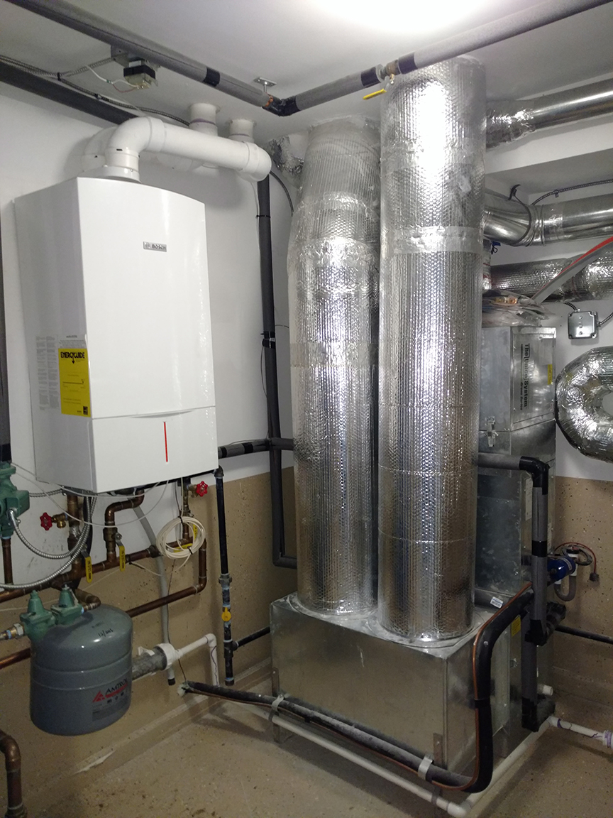
Choose the highest performing boiler that project funding will allow to meet the design heating load of the project. The highest performance boilers are sealed-combustion, direct-vent boilers, which can have Annual Fuel Utilization Efficiencies (AFUE) exceeding 94%. These are also the safest boilers to install within a home because they draw combustion air from and release combustion byproducts directly to the outdoors.
Calculate the heating load for the home and properly size the boiler and distribution system to meet this load. Look at the boiler’s output rating and if the design load is equal to or lower than the equipment’s lowest output rating, consider alternative heating equipment options that better match the design load of the home.
Select a boiler with a modulating burner for increased efficiency.
Install in accordance with relevant standards including ACCA Standard 5: HVAC Quality Installation Specification and the Technician’s Guide & Work Book For Quality Installations and ACCA Standard 9: HVAC Quality Installation Verification Protocols.
Set equipment control settings to optimize system efficiency. See the Building America report Condensing Boilers – Control Strategies for Optimizing Performance for guidance.
For condensing boilers, install an outdoor reset control to match system output to actual load and recommend that homeowners do not use a night-time temperature setback strategy. Select settings for the boiler reset curve and flow rates to optimize the performance in the system and to ensure that the return temperatures are low enough to promote condensing (Arena 2012).
Design an efficient zoned distribution system with a compact piping layout, insulated pipes, and correctly sized equipment for the radiators, baseboards, convectors, or radiant floor loop system. For hydro coil forced-air heating systems, design a compact duct layout following the Air Conditioning Contractors of America (ACCA)’s Manual S duct sizing guidelines and install ducts properly in accordance with ACCA Manual D for maximum airflow and efficiency.
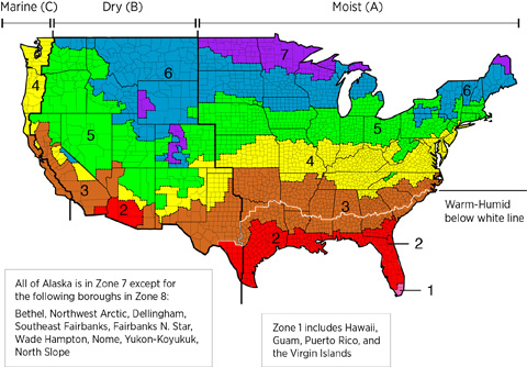
If you are participating in an energy-efficiency program, select a boiler whose efficiency complies with the requirements for your climate zone, as described in the Compliance tab.
To determine your climate zone, see the International Energy Conservation Code (IECC) climate zone map on the Climate tab.
See the Compliance Tab for links to related codes and standards and voluntary federal energy-efficiency program requirements.
Description
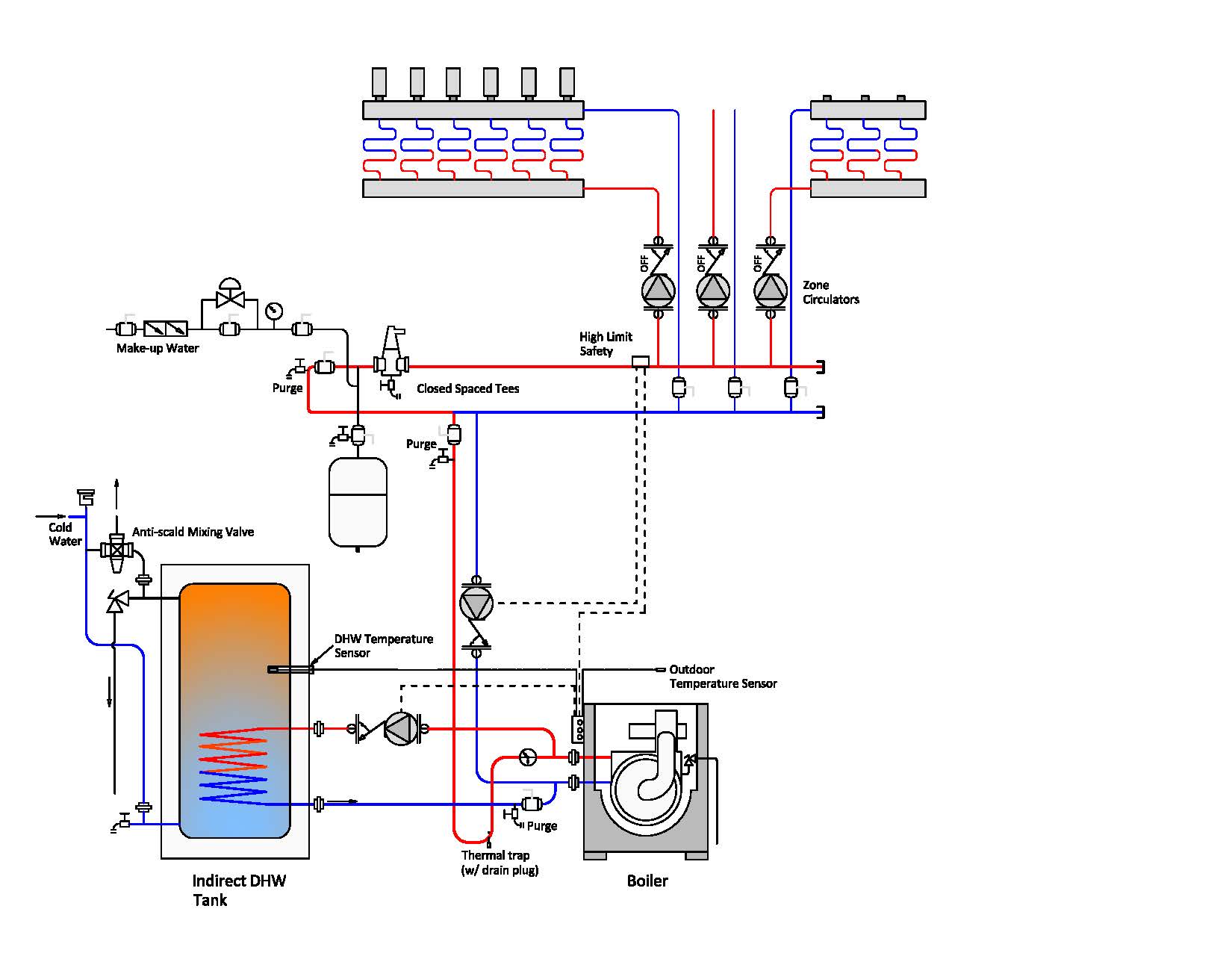
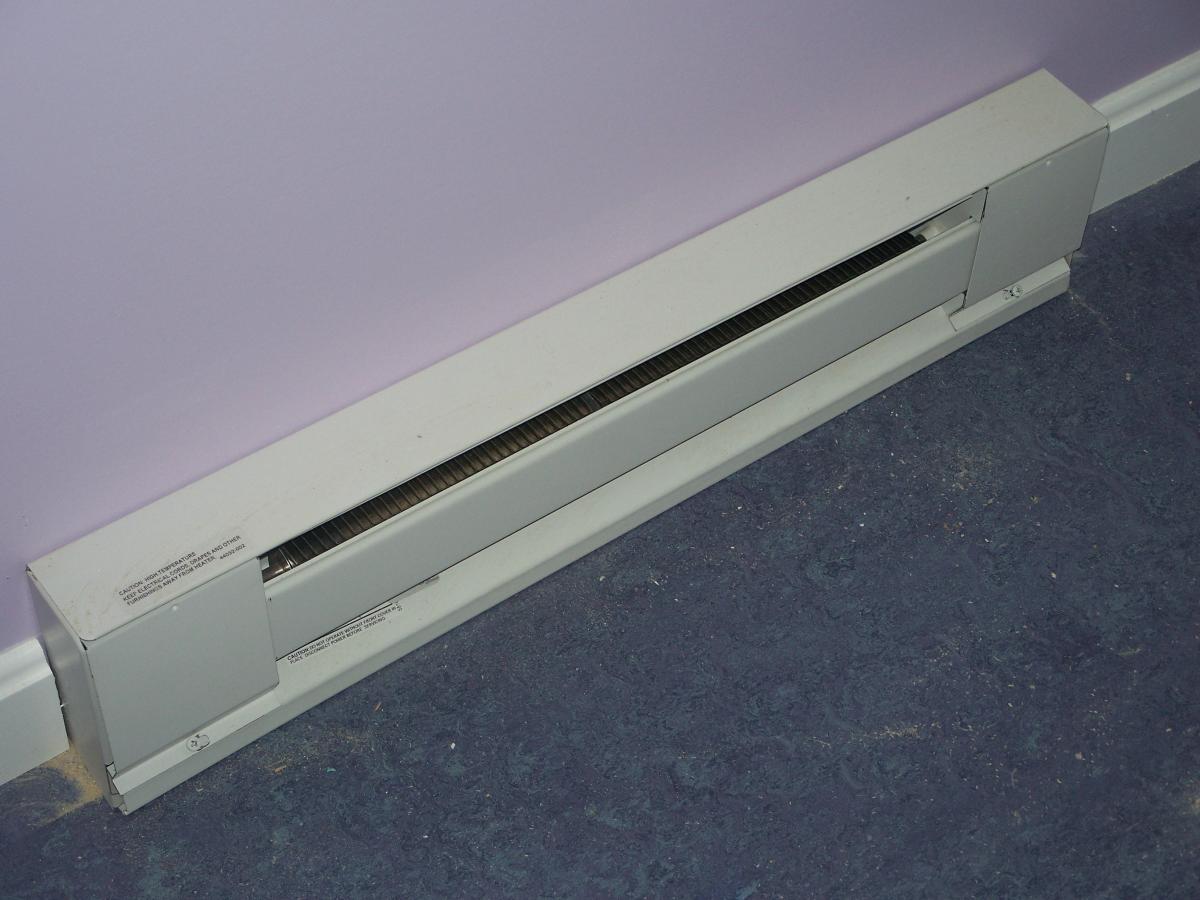
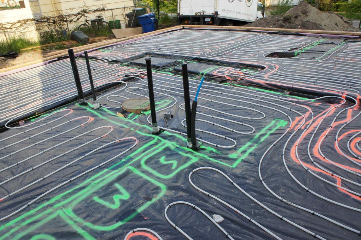
According to the U.S. Energy Information Administration (EIA), up to 11% of existing households use some form of hot water or steam heat (EIA 2009). Boilers produce hot water that can be used to heat homes through several different distribution methods. The hot water can be sent through plastic pipe loops in the floor for radiant floor heat or through metal radiators mounted along the wall or baseboard radiators mounted near the floor. Hot water can also be directed from a combustion tank water heater to a coil in an air handler equipped with a fan to blow air across the coil and through supply air ducts to the home. Most combustion boilers are fueled by natural gas. Fuel oil, propane, and wood are other fuel sources used in locations where natural gas is not readily available. The hot water for a boiler may also be heated or preheated by a solar thermal water heating system, a ground-source (geothermal) heat pump, or an air-source heat pump. The boiler may heat water in a tank or it may be a tankless (instantaneous) wall-hung model. Some boilers provide heat for a potable hot water tank in addition to providing hot water to room heaters; this is referred to as indirect water heating. Some newer, very efficient models combine space heating, water heating, and heat recovery ventilation.
For best performance, the heating system should be properly sized to match the heating design load of the home, as described below. If the home is constructed with high levels of insulation and air sealing, a smaller heating system can often be installed. When equipment is oversized, it can “short cycle,” or turn on and off repeatedly before the demand is met, which can have negative impacts on energy use, comfort, and equipment durability.
Combustion boilers, furnaces, and water heaters are classified by the International Mechanical Code (IMC) and in the National Fuel Gas Code. Understanding the descriptions of these appliance types based on both codes is important with respect to safety and efficiency.
The International Mechanical Code classifies boilers based on vent type: direct, mechanical, or atmospheric. Per the 2009 and 2012 International Mechanical Code, Chapter 2 Definitions:
- a direct-vent appliance is one that is constructed and installed so that all air for combustion is derived from the outdoor atmosphere and all flue gases are discharged to the outside atmosphere;
- a mechanical draft system is a venting system designed to remove flue or vent gases by mechanical means consisting of
- an induced draft portion under non-positive static pressure; or, a forced draft portion under positive static pressure;
- a natural draft system is a venting system designed to remove flue or vent gases under non-positive static vent pressure entirely by natural draft.
The 2015 National Fuel Gas Code (NFPA 54) puts furnaces in four categories based on flue vent pressures, flue gas temperatures (relates to condensing or non-condensing), and vent pipe materials, as shown in Table 1.
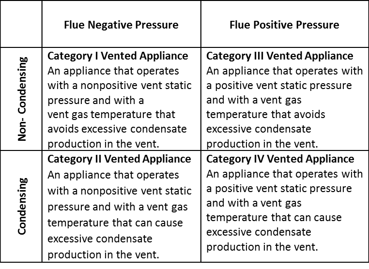
The lowest efficiency boilers are atmospherically vented, Category I boilers. A Category I boiler operates with the flue at negative pressure with respect to the combustion appliance zone (CAZ), i.e., the room in which the boiler is located, and the stack temperature is above 140°F, which is hot enough to avoid condensation in the vent. The burner draws its combustion air from the CAZ. The combustion chamber is also open to the CAZ; i.e., if you are standing next to the boiler, you can peer in and see the burner and the flames.
Older Category I boilers use an open draft hood that allows dilution air to enter the vent pipe and mix with the exhaust gases (Figure 1). A draft diverter at the base of the flue protects the flame from downdrafts coming down the chimney or flue. These older boilers are not mechanically drafted but are called natural draft (or atmospheric draft) because they rely entirely on high flue temperatures (relative to outside temperatures) to draw exhaust gases up and out of the flue. Because so much of the heat goes up the chimney, natural draft boilers have very low Annual Fuel Utilization Efficiency (AFUE) ratings, usually 70% or less.
A newer type of Category I boiler replaced the draft hood with a small fan, referred to as an induced draft fan, which pulls air through the combustion chamber, although the boiler still relies on flue temperatures to lift the combustion gases up the flue stack. The induced draft fan helps to prevent back drafting on startup and assists in getting the draft started. Once the vent pipe gets up to temperature (140°F+), a draft is established and the pressure inside the vent pipe (on the positive side of the fan) becomes negative with respect to the CAZ. The induced draft fan did away with the draft hood and dilution air, which wasted energy. Category I boilers that incorporate an induced draft fan typically have cleaner or more complete combustion than their older counter parts and therefore expel less pollutants in the air. The improved Category I boilers and furnaces also have an electronic ignition rather than a standing pilot light. Induced draft Category I boilers can have efficiencies of 78% to 83%.
ENERGY STAR permits naturally drafted boilers in IECC climates zones 1 through 3 and the DOE Zero Energy Ready Home program permits them in climates zones 1 and 2, if they have an AFUE of ≥ 80%. However, draft-hood-equipped boilers are very unlikely to exceed 70% efficiency, so essentially all ≥ 80% boilers and furnaces are induced draft or power vented or direct vent. When naturally drafted boilers and furnaces are installed, a combustion safety test must be performed.
An induced draft fan-equipped boiler or furnace is considered mechanically drafted. However, because it is still open combustion (i.e., it draws its combustion air from the CAZ) and because it relies on negative flue pressure to carry away combustion byproducts, it can, like the naturally vented boiler or furnace, have the potential to backdraft. Backdrafting, when combustion gases spill down into the CAZ rather than going out the flue, can occur if the CAZ becomes depressurized with respect to the flue. Several things could cause this to occur – running multiple exhaust fans and the dryer and the fireplace all at the same time, for example.
Figures 1 and 2 below are Category I boilers. The boiler in Figure 1 uses the older technology of a draft hood, which pulls dilution air into the vent pipe. The newer boiler in Figure 2 replaces the draft hood with a small induced-draft fan that pulls the products of combustion through the combustion chamber and flue by pushing the byproducts of combustion out through the vent pipe.


Category II applies to some commercial furnaces but no residential appliances.
A Category III combustion appliance has a vent pipe that is under positive pressure and the appliance is non-condensing, meaning its flue gases only go through one heat exchanger then exit through the vent at temperatures above 140°F. Category III appliances may include instantaneous gas water heaters and gas- or oil-fired boilers. For further discussion of oil-fired boilers, see the guide Oil-Fired Boilers.
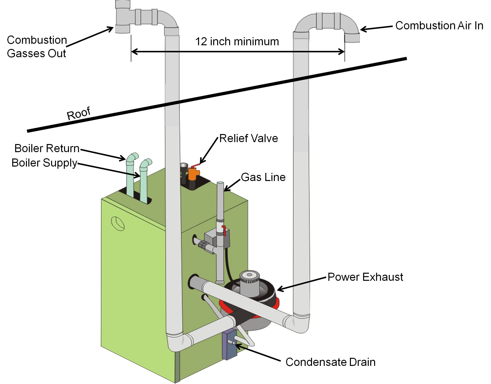
Category IV boilers are combustion appliances that have a vent pipe under positive pressure and flue gases under 140°F. The vent exhaust is low temperature because Category IV appliances are equipped with two heat exchangers (or sometimes one extra-large heat exchanger). In the second heat exchanger any remaining heat in the combustion air is extracted and water vapor (a byproduct of combustion) cools and condenses to liquid water. This liquid is drained to the sewer or outside through a condensate drain. The condensate is highly acidic (pH ≤ 3) so local code may require that it be pretreated before disposing to the sewer. (See Condensing Boilers.)
Category III and Category IV boilers are both forced draft (also referred to as power vented) appliances meaning that they are equipped with a combustion fan that is located before the burner to push air through the combustion chamber and out of the vent (Figure 5). The fan is continually operating when the burner is firing so the vent stack pressure is always positive. The byproducts of complete combustion are CO2, H2O, and N.
Category IV boilers, like Category III boilers, vent their combustion exhaust gases directly outside through a sealed pipe so they cannot be back drafted. Category III and IV appliances should be installed as sealed-combustion/direct vent appliances, which means their combustion chamber is sealed off from the CAZ and they draw their combustion air from outside via a second vent pipe or concentric pipes that bring combustion air directly to the combustion chamber from outside the home. However, although manufacturers do not recommend it, they are sometimes installed as non-direct-vent appliances (where the exhaust pipe is installed but the pipe for incoming air is not installed so the boiler draws its combustion air from the CAZ).
Category IV boilers can be either gas fired or oil fired. For more information oil boilers refer to the guide Oil-Fired Boilers. For more on Category IV boilers see Condensing Boilers.
Since 1992, the U.S. Department of Energy (DOE), under the National Appliance Energy Conservation Act, has required that small gas boilers have an AFUE of at least 80%. In November 2007, the DOE established a revised minimum efficiency standard of 82% for residential boilers, which will take effect in November 2015. To be ENERGY STAR labeled, a boiler must have an efficiency of 85% or higher.
ENERGY STAR Single-Family New Homes (Version 3, Rev 11) allows gas and oil furnaces and boilers to be ≥ 80% AFUE in Climate Zones 1, 2, and 3. In Climate Zones 4-8, ENERGY STAR requires that boilers be ≥ 85% and ENERGY STAR labeled.
The DOE Zero Energy Ready Home program allows ≥ 80% AFUE boilers in Climate Zones 1 and 2 only. In Climate Zones 3 and 4 (except marine climate zone 4), boilers must have an AFUE of ≥ 90% and in Climate Zones 5 through 8 (plus marine climate zone 4), boilers must have an AFUE of ≥ 94%.
Boiler Controls
While older boilers are either on or off, newer boilers with multi-stage or modulating burners have adjustable output to better match heating loads. This reduces the number of on-off cycles (and cycling losses) and allows the boiler to operate for longer hours at lower firing rates, which improves efficiency. Non-modulating boilers have efficiencies of 85% to 90%. Boilers that operate in modulation mode rather than just on-off can improve average boiler efficiency by up to 8%. Higher-efficiency models are also equipped with electronic controllers that can increase equipment life, improve boiler efficiency, and enhance comfort, by adjusting boiler water temperature, creating time-delay relays, performing automatic post-purge, preventing warm-weather boiler operation, controlling the position of mixing valves, and controlling pump speeds. These controls can increase the efficiency of noncondensing boilers by 10% or more and reduce idle losses to 0.3%. Condensing gas boilers that are fully modulating and have advanced controls can achieve efficiencies ranging from 92% to 96%.
There are many settings that can be adjusted on a modern boiler to improve the efficiency and comfort performance of the equipment, these adjustments may provide better performance than the default factory settings.
An outdoor reset control, which matches the system output to the actual outdoor temperature conditions, will improve comfort for owners of both condensing and non-condensing equipment by preventing extreme spikes in indoor temperature when the outdoor temperatures are warmer than design conditions. If you install an outdoor reset, recommend that homeowners do not use a night-time temperature setback strategy unless special controls have been installed that can override the reset control. Locate the outdoor sensor where it will not be exposed to a heat source such as direct sunlight or a dryer exhaust vent.
When installing an outdoor reset control with a noncondensing boiler, choose settings so that the return temperature to the boiler is no lower than 140°F to prevent condensing. However, when selecting the outdoor reset curve set points for a condensing boiler, choose settings so that the temperature of the water returning to the boiler is below 130°F. This ensures that the return temperatures are low enough to promote condensing, which will greatly increase the energy efficiency of the system (see Arena 2012 for more details). To ensure the return temperature is below 130°F, the supply temperature will likely have to be reduced to below the factory setting. Make sure the heat emitters used (baseboards, radiators, etc.) are properly sized based on the average temperature in the distribution loop. If undersized, they won’t release enough heat to the space and the water will return to the boiler at too high a temperature, preventing condensing. Radiant floor systems are typically set up to run at lower temperatures when installed, so they do not require additional adjustment to the boiler’s supply temperature.
If you are specifying toe kick heaters in homes that have condensing boilers with outdoor reset controls, make sure the toe kick model specified is capable of operating at low temperatures. Many of the toe kick heaters currently available will not operate below a supply temperature of 140°F. A properly designed and configured condensing hydronic system will have return temperatures below 130°F most of the year, leaving the occupants without heat in rooms with toe kick heaters.
In highly insulated, energy-efficient homes with correctly sized equipment, nighttime setback can cause comfort issues and customer complaints. A boiler that is correctly sized to meet the home’s design heating load will not have enough capacity to recover from the setback in a reasonable amount of time, especially if the system is designed with an outdoor reset control. Outdoor reset controls match the boiler’s supply temperature to the heating load based on the current outdoor conditions, severely hindering the system’s ability to raise the temperature in the space. If the boiler was set up with an outdoor reset control and no capability to override it, advise homeowners not to set their thermostat temperature back during nighttime hours. This is also recommended if the home is highly energy efficient and the boiler was sized to meet the design heating load.
If you know that the homeowner will employ a setback strategy or if you would like to provide that capability, you can install controls to speed up temperature recovery such as 1) a boost control that automatically raises the boiler output target temperature if heating demand is not satisfied within a set number of minutes, 2) an indoor sensor that works with the outdoor reset control to compensate for lags in response based on interior temperature, or 3) a simple manual override switch. Oversizing the heat emitters and possibly the boiler may be necessary to meet the additional load induced during periods of setback recovery.
If the boiler is oversized compared to the design load, oversizing the heat emitters will help reduce short cycling of the boiler. This may be the only option in situations where the smallest boilers are too large for the design load or there are several zones, each of which has very small loads compared to the boiler’s capacity. In these cases, oversizing the emitters will reduce cycling, improve response time, and increase efficiency. Note that many manufacturers set a maximum temperature difference between the boiler’s supply and return to protect the heat exchanger. Oversizing the heat emitter will result in an increase in the delta T, so make sure that you do not oversize to the point that the manufacturer’s limit is exceeded. If installing a non-condensing boiler, make sure that increasing the emitter does not result in return water temperatures below 140°F.
For both condensing and noncondensing boilers, a warm weather shutoff turns off the boiler when the temperature setting is exceeded by the outdoor temperature. Boilers commonly come from the factory with the shutoff set between 68°F and 72°F. In locations with large day-night temperature swings or in spring and fall in homes that use a setback, if the shutoff is set too low, warm midmorning outside temperatures could prevent the heat from coming on even if it is still cold inside. Make sure the warm weather shutoff setting is no lower than the desired indoor winter temperature. For example, if 70°F is the normal setting, the warm weather shutoff should be no lower than 70°F.
Make sure your system includes an automatic post purge control, which keeps the system pump on for several minutes after the boiler stops firing to disperse the heat still residing in the mass of the boiler.
Some boiler manufacturers have started offering controls that can limit the boiler’s maximum input. This can be especially useful if the boiler is used for both space heating and domestic hot water and one load is significantly less than the other. This limit reduces cycling in situations where the boiler’s maximum firing rate is significantly higher than the demand, for example if when the water heater is calling for heat but the space heater is not.
Heat dumping is a strategy that diverts excess boiler heat to the domestic hot water (DHW) tank after the space heating demand is satisfied. Studies have shown this technique can greatly improve overall system efficiency (Butcher 2011).
See the Building America measure guideline report: Condensing Boilers—Optimizing Efficiency and Response Time During Setback Operation for additional guidance on setting boiler controls.
Distribution
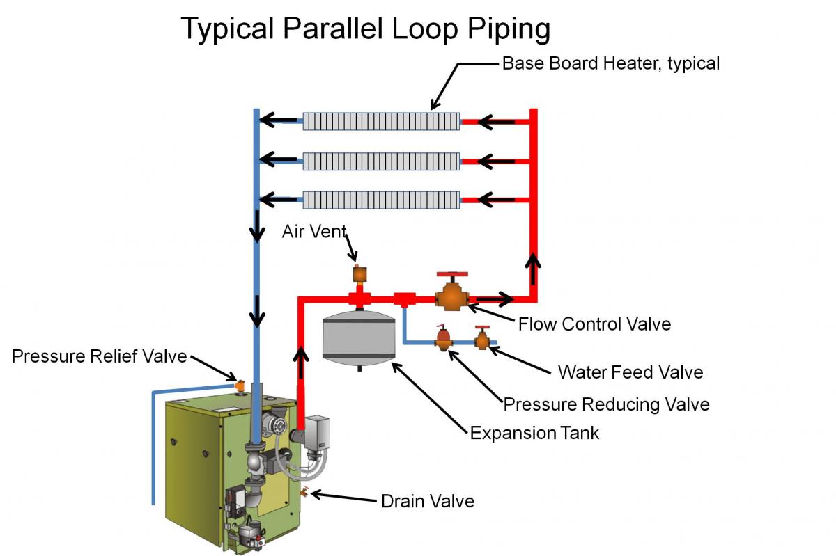
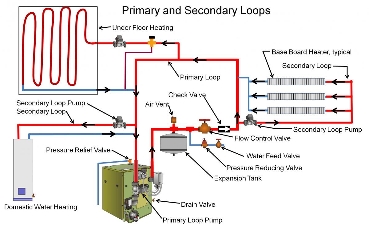
One of the big advantages of hot water heating is the ease with which it can be zoned. Radiant heating systems in older homes were often set up in a series with a single pipe going from the boiler to first one radiator than the next (with subsequent loss of temperature in each successive emitter). But newer distribution systems feature parallel or primary-secondary piping arrangements with separate zones that can be controlled by separate thermostats to easily accommodate different temperature set points and schedules.
How to Select and Install a Boiler
- Choose the highest performing boiler that project funding will allow to meet the design heating load of the project. If you are participating in an energy-efficiency program, select a boiler that complies with the requirements for your climate zone, as described in the Compliance tab.
- Install in accordance with relevant standards including ACCA Standard 5: HVAC Quality Installation Specification and the ACCA’s Technician's Guide for Quality Installations and ACCA Standard 9: HVAC Quality Installation Verification Protocols.
- Design an efficient distribution system that allows for zoning.
- Properly size the boiler by first calculating the heating load of the home. Calculate heat load as described in the ASHRAE Fundamentals Handbook. Many software products are also available that can guide you through the calculations, and several boiler manufacturers include sizing guidelines or software on their web sites. If the design load is equal to or lower than the selected boiler’s lowest output rating, consider alternative low-load heating equipment options that better match the design load of the home.
- Install the boiler as a direct-vent installation where combustion air is piped directly to the boiler combustion chamber from outside. If the boiler must use the CAZ for combustion air, verify that required combustion air is provided in the CAZ and perform a combustion safety test after installation. room. See methods for calculating and providing combustion air in the guide Combustion Furnaces.
- Select appropriate vent piping in accordance with the National Fuel Gas Code (see the Compliance tab).
- Set the equipment control settings to optimize system efficiency as described above and in Arena 2012.
- If your boiler heats a hydro coil for forced air heating, see Compact Air Distribution and Proper Sizing of HVAC Ducts.
- After the boiler is installed and before the initial filling, fill the system with water plus a cleaning solution. Allow this to circulate for several hours to remove grease, oil, and chemicals from solder and flux. Drain then fill with clean water. If the city water is corrosive, include an initial treatment. If properly installed, the boiler should operate indefinitely without needing additional water or cleaning.
- For condensing boilers, ensure that condensate drains properly to the sewer or directly outdoors. Because the condensate is highly acidic, follow local code requirements regarding pretreatment of condensate before disposing to the sewer. Protect the condensate line from freezing. Provide a secondary (emergency) drain pan constructed of durable material.
- Verify correct boiler operation by testing the outdoor reset control, and evaluating the boost control if one is installed.
Ensuring Success
Choose a Category IV high-efficiency, sealed-combustion, direct-vent system whenever possible.
Verify that the boiler is not oversized for the home’s heating load.
If you choose a Category I or non-direct vented boiler (not recommended), before installation, calculate the required adequate combustion air for the selected boiler model and verify that that amount is provided in the CAZ. If the boiler is a Category I boiler, a BPI- or RESNET-certified rater should perform a combustion safety test after installation.
For Category IV boilers, ensure that the horizontal portion of the exhaust vent pipe slopes slightly toward the boiler. Follow local code requirements regarding whether the condensate should be drained to the sewer and treated before draining to reduce its acidity. Ensure that the condensate line is in a location where it will not freeze. Also ensure that a drain pan is installed under the boiler as a backup measure.
After installation, inspect to verify the following in accord with ACCA Standard 5: HVAC Quality Installation Specification and the ACCA’s Technician's Guide for Quality Installations and ACCA Standard 9: HVAC Quality Installation Verification Protocols. These standards address quality installation and commissioning requirements for vapor compression cooling systems, heat pumps, and combustion and hydronic heating systems.
- Verify that any baseboard emitters installed are large enough to deliver the capacity needed.
- Ensure a minimum of a 20°F temperature differential between the supply and return temperatures under design conditions.
- Ensure that the temperature setting on the boiler reset curve is below the boiler’s high limit setting.
- Verify that the warm weather shutoff is high enough to prevent no-heat situations during the swing seasons.
- Verify that the outdoor reset sensor has been placed away from any exhaust vents including kitchen, bath, dryer, and mechanical system vents and that it will not be in direct sunlight during any portion of the day.
Region
The map in Figure 1 shows the climate zones for states that have adopted energy codes equivalent to the International Energy Conservation Code (IECC) 2009, 12, 15, and 18. The map in Figure 2 shows the climate zones for states that have adopted energy codes equivalent to the IECC 2021. Climate zone-specific requirements specified in the IECC are shown in the Compliance Tab of this guide.

Cold Climates
In cold climates, in addition to proper sizing, it is critical to use sealed-combustion, direct-vent, or power-vented equipment. It is also critical to make sure that the air intake and exhaust discharge vents are located sufficiently above anticipated snow line. The intake should be sufficiently separated from the exhaust vent to prevent frost buildup on the cold air intake pipe. The exhaust discharge must be sufficiently high so that frozen condensation that may accumulate on the ground will not block the exhaust pipe. Condensate lines should be directed to an indoor drain.
Training
Right and Wrong Images
Source
Source
Source
Source

Source
Compliance
ENERGY STAR New Homes and Apartments
International Energy Conservation Code (IECC)
International Residential Code (IRC)
International Mechanical Code (IMC)
Air Conditioning Contractors of America (ACCA) Standards
ACCA Manual S - Residential Equipment Selection
ACCA Manual D - Residential Duct Systems
ACCA Manual J - Residential Load Calculation
ACCA Standard 5: HVAC Quality Installation Specification
ACCA Standard 9: HVAC Quality Installation Verification Protocols
Retrofit
SCOPE
Assess the need for replacing or upgrading the HVAC system.
Review the guide Pre-Retrofit Assessment of Combustion Appliances to ensure safe conditions exist and unsafe conditions won’t be introduced if combustion appliances are upgraded or replaced or if other energy-efficiency upgrades are made to a home with combustion appliances.
For more information on gas-fired boilers, see the U.S. Department of Energy’s Standard Work Specifications regarding gas-fired boilers.
DESCRIPTION
Assessment
The typical lifespan of HVAC equipment is 15 to 20 years, but boilers can often last for many decades. New equipment has much higher efficiencies, safety, control flexibility, and performance capabilities. Existing equipment should be carefully assessed to determine whether an investment in repairs, upgrades, or expansion is warranted. See the following BASC guides and resources for information to aid in making this determination. The guides also contain important safety and health information for dealing with older homes and equipment.
- Existing HVAC System Upgrade or Expansion
- Building America Best Practices Series Volume 14 - HVAC: A Guide for Contractors to Share with Homeowners
Replacement
Although replacement of HVAC equipment can be costly and labor-intensive, it often reaps large rewards in energy cost savings and comfort. Use existing utility bills, the estimated cost of replacement equipment, the nameplate efficiencies of potential new equipment, and the savings estimates in Table 1 to roughly determine expected energy cost savings resulting from the replacement of existing HVAC equipment with equipment having higher rated efficiencies.
| Existing System AFUE | New/Upgraded System AFUE | ||||
|---|---|---|---|---|---|
| 75% | 80% | 85% | 90% | 95% | |
| 50% | $33 | $38 | $41 | $44 | $47 |
| 55% | $27 | $31 | $35 | $39 | $42 |
| 60% | $20 | $25 | $29 | $33 | $38 |
| 65% | $13 | $19 | $24 | $28 | $32 |
| 70% | $7 | $13 | $18 | $22 | $26 |
| 75% | - | $7 | $12 | $17 | $21 |
| 80% | - | - | $6 | $11 | $16 |
| 85% | - | - | - | $6 | $11 |
| 90% | - | - | - | - | $5 |
| *Assuming the same heat output | |||||
If a decision is made to replace the equipment, it can be replaced in-kind or with a different type of system.
A moderate change to a hydronic heating system would retain the piping and terminal units and simply replace the traditional boiler with a condensing boiler, which often provides comfort advantages (due to controllability) in addition to higher efficiency. See the article titled Features and Advantages of Condensing Boilers for an overview.
A bigger change would be a ductless air source heat pump. Several models are now available that can reliably and comfortably provide heating at lower outside temperatures than was previously possible, and may now be considered a reasonable replacement in colder regions, depending on the climate zone and building enclosure. They offer the added benefit of cooling from the same equipment. Ductless air-source heat pumps eliminate the need to install ducts if no ducts currently exist in the home.
If the existing boiler for a radiant heating system is also serving the domestic water heating system, a change to a different type of HVAC system will require a new, independent domestic hot water heater as well.
See the following Solution Center guides for more information on other types of HVAC systems:
- Combustion Furnaces
- Oil-Fired Boilers
- Condensing Boilers
- Heat Pump: Traditional Split
- Heat Pump: Mini-Split
- Geothermal Heat Pumps
Repair/Upgrade
Full system maintenance is often overlooked by homeowners who don’t understand the strong relationship between general maintenance and performance. Proper inspection and maintenance of the equipment can yield significant improvements in performance, especially in steam and hot water heating systems. See Boiler Inspections for Safety, Life and Efficiency for guidance.
A “water-logged pressure tank” can cause poor heating control and air entrainment in the system. The following manufacturer website gives step-by-step instructions to remedy this condition: Fixing an Expansion Tank with Excess Water.
Some basic descriptions and maintenance tips for the expansion tanks in hydronic heating systems can be found in these articles from Contractor Magazine:
- Why expansion tanks need to be understood
- Expansion Tanks 101: pressure and air vents
- Expansion Tanks 101: the facts and myths
The Air Conditioning Contractors of America Association, Inc. (ACCA) is one of the best sources for guidance on the design, sizing, installation, commissioning, and maintenance of radiant hydronic HVAC equipment. An overview of the guidance and training they offer can be found on the ACCA website under Radiant & Hydronics - ACCA.
Their free Quality Standards can be found on the ACCA website.
Useful documents available for download from the ACCA website include the following:
- ACCA Standard 5 (2015): HVAC Quality Installation Specification - minimum design and installation requirements for HVAC applications by professional contractors following industry-recognized quality installation practices.
- ACCA Standard 12 (2014): Home Evaluation & Performance Improvement - minimum requirements to evaluate a residence with regard to energy efficiency, water conservation, occupant comfort, and indoor air quality.
- ACCA Standard 9 (2016): HVAC Quality Installation Verification Protocols - requirements, roles, and obligations of installers and others to ensure that HVAC installations comply with the ANSI/ACCA 5.
- ACCA Standard 4 (2013): Maintenance of Residential HVAC Systems - minimum level of acceptable compliance for HVAC equipment maintenance inspections for residential applications.
- ACCA Standard 6 (2015): Restoring the Cleanliness of HVAC Systems - procedures for cleaning HVAC systems.
Additions
If additional rooms will be added to the home, or if an attic, basement, or garage will be converted to living space, it may be possible to add terminal units to the existing boiler if an accurate load calculation is performed and confirms that the boiler has sufficient capacity. Install the new radiators or convectors where needed. If possible, install independent zone controls (i.e., the zone valve is controlled by a dedicated thermostat) to provide optimum comfort and efficiency.
SUCCESS
Some very old gas or oil furnaces and boilers may have asbestos jacketing or insulation on the equipment, piping, and even ductwork. See the EPA’s website Information for Owners and Managers of Buildings that Contain Asbestos for more on remediating asbestos.
COMPLIANCE
Check with the Authority Having Jurisdiction to determine if upgrade or expansion to existing HVAC equipment requires compliance with current codes.
See Compliance tab.
More Info
Case Studies
References and Resources
*For non-dated media, such as websites, the date listed is the date accessed.
Contributors to this Guide
The following authors and organizations contributed to the content in this Guide.
Sales
High-Efficiency Gas Boiler = High-Efficiency Gas Boiler

Technical Description
Gas boilers burn natural gas to heat water and then distribute heat to the home via radiators, a duct system, or radiant floor heating loops. High efficiency gas boilers use sealed-combustion with two ducts that fully isolate the combustion process. This includes one duct that draws combustion air from outside the home and one duct that exhausts flue gases directly outside. Thus, sealed combustion eliminates the possibility of back-drafting harmful flue gases back into the home or consuming too much oxygen. These boilers optimize efficiency with a condensing process that extracts heat from exhaust gases with a secondary heat exchanger. High-efficiency gas boilers meet ENERGY STAR requirements for efficiency. Ultra-efficient gas boilers meet or exceed the criteria for ENERGY STAR’s “Most Efficient.”
Questions? Comments? Contact our webmaster.