

Scope

Planning and Design
The builder, architect or designer, and HVAC contractor should coordinate the location of HVAC equipment and ducting prior to finalizing construction drawings, with the goal of minimizing the total effective length (TEL) of the duct system. (TEL = linear feet of duct + equivalent length of duct fittings.)
Duct and Equipment Layout and Grille Selection
- Locate furnace or heat pump air handler as close to the center of the house as possible.
- Locate supply grilles close to interior walls of rooms where possible. Side wall registers are preferred.
- Select supply grilles that provide sufficient throw to reach exterior walls.
- Avoid supplying air to low-load interior spaces such as closets and powder rooms.
Duct and Equipment Sizing
- Use ACCA Manual J to calculate loads using the 0.06/0.06 cfm/sq.ft. supply/return leakage assumption (Leakage Class CL-3), the appropriate insulation (R-8 for attic ducts), and the 7C-AE duct location option.
- Size equipment in accordance with Manual J and the ENERGY STAR HVAC System Quality Installation Checklist.
- Use ACCA Manual D to size ducts based on Manual J loads.
Duct Installation
- Tightly seal all duct connections and joints with mastic and test to confirm a leakage rate of not more than 5% of total system airflow.
- Stretch flex ducts out to full length and avoid kinks and compression.
- Install ducts in conditioned space, either in an insulated non-vented attic or crawlspace or buried in attic insulation.
See the Compliance Tab for links to related codes and standards and voluntary federal energy-efficiency program requirements.
Description
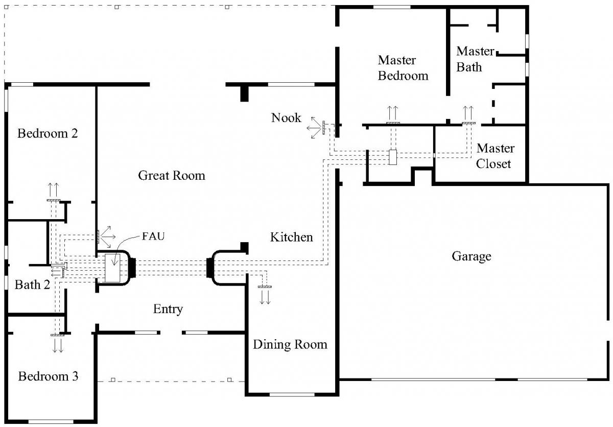
A compact duct system locates the heating/cooling equipment and supply plenum near the center of the home, and locates each room supply grille as close as possible to the supply plenum (see Figure 1). The advantages of a compact duct system are numerous, yet they are rarely used in mainstream production home construction as builders, HVAC contractors, and buyers have come to expect conventional designs. A small group of home performance HVAC contractors have been successfully designing and installing compact duct systems for decades.
There are many advantages to following compact duct design practices as part of an integrated high-performance ducted HVAC installation and a high-efficiency building design. Combining the benefits of a compact duct design with best practices for airflow and air balance, refrigerant charge, duct sizing, fan Watt draw, register selection for optimal throw and mixing, etc., will result in the best possible performance and optimal comfort. for guidance on using compact duct design in home additions, see the Retrofit tab.
Major Advantages
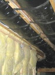
- Lower Installation Costs – The length of duct runs can be reduced by 50% in many cases compared to standard practice, saving money on both materials and labor. Labor savings are also achieved by working predominantly in accessible areas. For example, traditional register locations along exterior walls make it more difficult to insulate supply boots because there is so little room between the ceiling and the roof decking and top truss chords at the eaves of most attics. See Figure 2.
- Lower Duct Losses – Less duct surface area translates to decreased conductive and leakage losses. As the physical size of ducting is reduced by installing fewer and shorter supply duct runs, both duct surface conductive losses and the number of duct connections are reduced. Smaller ducts are also easier to bury in attic insulation or to locate within conditioned space.
- Equipment Downsizing – Reducing duct leakage and thermal gains eliminates a portion of the equipment load, making it possible to use smaller capacity equipment, which further decreases the required size of the ducts. Smaller equipment is often less expensive for the HVAC contractor to purchase and install and uses less energy.
- Higher Comfort Levels – Some of the most common comfort complaints relate to improper air distribution and can be a result of incorrectly sized ducts, poor selection of supply grilles and locations, incorrect system air balance, and minimal mixing due to excessive stratification and short run times. Long duct runs with numerous turns and branches increase static pressure in the lines, cutting air flow and increasing noise. Short straight duct runs move air more efficiently and effectively for better distribution to all rooms of the house with less noise and less energy consumption. With smaller, less expensive, compact duct systems and equipment, contractors can focus more resources on room-by-room load calculations and proper design and installation without increasing builder costs, with the end result being optimal occupant comfort.
- Easier for the Ceiling Insulation Installers – Reducing the amount of ducting in attics makes it easier for the insulation installers to do a good job, whether ducts are in a conventional vented attic, a non-vented attic, buried in ceiling insulation, or in attic duct chases. Attics that are packed with ducting make it difficult for insulation installers to physically get to where they need to be to properly insulation the floor of the attic. This is especially true in homes with lower roof slopes and in areas close to the eaves.
- Ducts Are Less Susceptible to Damage – Minimizing the amount of ducting in the attic reduces the chance of the duct system being damaged by other trades during construction, or by the homeowner (after occupancy).
Myths of Duct Design
There are three primary myths that are often responsible for oversized and inefficient duct system designs.
- Air Must be Delivered at the Window. This notion has its roots in cold climates in the days before double-glazed, low-U-value windows. For homes with single-glazed windows, especially in cold climates, warm high-velocity air had to be delivered to the windows to prevent condensation and ice formation. Today’s affordable high-performance windows have 75% less heat loss than older single-glazed windows, so locating the supply grille at the window is no longer necessary, even in most cold climates.
- Short Circuiting. One widely held belief among HVAC contractors is that if the supply grille is close to an interior wall, the opposing side of the room won’t receive sufficient air. They assume registers must be on exterior walls and point toward the return air grille at the center of the home. This concept may seem logical, but a properly selected supply grille will deliver high-velocity air (500-700 ft/minute) in a plume that will travel at least three-quarters of the way across most typically sized great rooms. In compact duct designs, the air plume will usually strike the far wall of the room at a measurable velocity. For example, if 220 CFM is delivered from a 10” x 6” high-sidewall double-deflection supply grille, the air plume velocity won’t drop below 50 feet per minute until the plume has traveled 28 feet. With the use of slightly more expensive aerodynamic grilles (rather than standard stamped grilles with fixed vanes), these long throws can be accurate and nearly silent with a Noise Criteria (NC) of less than 25, in the example just given.
- It’s the Way We Have Always Done It. Industry standard practices are difficult to change. Builders are accustomed to seeing very similar HVAC designs and installations from all of the contractors from whom they solicit bids. For an innovative contractor to deviate from this conventional wisdom requires that the builder recognize the value in that change. Home buyers who are accustomed to seeing supply registers at windows may not appreciate the value of an efficient compact design, which can become a marketing challenge for the builder. Pointing out the benefits and value of improved practices and educating builders, contractors, and home buyers is an important part of raising the performance level of HVAC systems in new homes.
How to Design a Compact Duct Layout
- Properly estimate the design room-by-room heating and cooling loads using ACCA Manual J.
- Locate heating and cooling equipment in a central location, preferably within conditioned space. This will allow for shorter distances and subsequently shorter duct runs from the equipment to conditioned spaces.
- Design the air distribution supply system in accordance with ACCA Manual D while paying particular attention to the following design guidance:
- Focus on minimizing the number of supply grilles. Large spaces such as an open great room that includes living space, kitchen, and dining area can often be served by one register, especially in efficient new homes.
- Identify spaces with low enough loads that a dedicated supply isn’t necessary. Depending upon the climate, this may be the case with powder rooms, interior half baths, utility rooms, and master closets. Add un-served loads to neighboring spaces.
- Select and size registers using manufacturer performance product data and ACCA Manual D Table A1-1 for noise control (e.g., use a maximum design velocity of 700 FPM, or manufacturer noise criteria (NC) of 30, for selecting supply registers, 700 FPM for supply trunks, and 600 FPM for rigid supply branches or 700 FPM for flexible supply branches.
- Locate supply air registers in accordance with ACCA Manual T. See also the California Energy Commission’s HVAC Design Guide.
- Supply grille air velocities should be 500 FPM to 700 FPM in both heating and cooling mode. The throw should be sufficient to extend the length of the room and to eliminate any stagnant areas.
- Locate supply registers high on interior walls whenever possible. This location results in the best air mixing and shortest duct runs. The next best option is on the ceiling close to the interior wall.
- Locate a single, central return trunk as close to the heating/cooling system as practical. To avoid excessive pressure drop, filter grilles must be sized for filters with the highest MERV ratings that are likely to be used.
- The return trunk should serve one return grille per living level (optionally two) to minimize or eliminate return trunks and branches.
- Provide return air paths from the bedrooms to the central return using transfer grilles (jump ducts can be substitutes if necessary).
- Size return ducts and select return grilles and transfer grilles in accordance with ACCA Manual D Table A1-1: Air Velocity for Noise Control (e.g., use a maximum design velocity of 500 FPM for rigid return ducts, 600 FPM for flexible return ducts, and 300 FPM (face velocity) for return grilles and transfer grilles).
- Design return duct geometry in accordance with ACCA Manual D Appendix 13: Noise Control (e.g., where the return grille is adjacent to the air handler, install a minimum of two duct elbows to help attenuate line-of-site noise from the blower assembly within the air handler).
- Use ACCA Manual S to correctly size the system. When determining equipment sizing per ACCA Manual S, use the original equipment manufacturer’s expanded performance table to obtain performance data at actual design conditions, rather than using the performance data on the AHRI certificate.
- Install the equipment and distribution system according to the design. Use balancing air dampers where necessary to ensure proper room-by-room airflow. See also the Building America Solution Center guides on duct installation, insulation, and air sealing.
- Commission the system by verifying the following:
- total airflow
- fan watt draw
- duct leakage
- room-by-room airflow.
Ensuring Success
- Consider a compact duct layout early during the design phase of a project, particularly where house designs must be altered to accommodate mechanical rooms, central duct chases, or ducts within floors or bulkheads.
- A compact duct layout (as all duct layouts) must be in accordance with industry standards (e.g., ACCA Manuals D, T, S, and J; see the Compliance tab).
Region
Applicable to all climates.
Training
Right and Wrong Images

Source
Presentations
Compliance
Retrofit
SCOPE
When the HVAC system in an existing home is going to be replaced with a new HVAC system that includes air distribution, consider replacing the duct system at the same time and installing the new duct system using a compact duct design strategy to improve system efficiency and performance.
- Refer to the ACCA Manual J report for room-by-room airflow requirements and design the new duct system per ACCA Manual D, with the shortest/straightest route possible to the interior walls of each room.
- Select ceiling or sidewall registers sized to the dimensions of each room and required air flow.
- Remove all existing ducts and registers, and patch/repair the floor or ceiling as required.
- Install the new ducts and registers, sealing all joints and connections with an approved sealing method.
- Test and balance all airflows to the values calculated by ACCA Manual J.
- Review the U.S. Department of Energy's Standard Work Specifications for guidance on specified steps and objectives for improving ductwork in existing homes.
- See the Building America Solution Center guide Pre-Retrofit Assessment of Attics, Ceilings, and Roofs for conditions to consider when working in attics.
DESCRIPTION
In an extensive energy efficiency retrofit of a home, the heating and cooling loads of that home will likely be significantly lower than in the pre-retrofit condition and the required airflows to each room in the home will likewise be lower. The existing space conditioning equipment and ductwork is therefore likely to be oversized, requiring the replacement of the equipment and ductwork following the retrofit.
A compact air distribution (duct) system relies on the throwing characteristics of high sidewall and ceiling registers. Floor registers do not have proper throw and spread to achieve good air mixing in the room; this is the case for both the cooling and heating seasons. When installing a compact air distribution system as part of an extensive home retrofit, any existing floor registers must be removed and replaced with ceiling or sidewall registers along the interior walls of the room. The registers should be sized to achieve proper air mixing in the rooms. The leftover holes in the floors and ceilings must be patched and repaired as part of the retrofit.
In homes where the existing ductwork is located inside the floor or ceiling framing cavity, it may be largely inaccessible to an installer when considering an air distribution system replacement. Therefore, a compact air distribution system is recommended only when an extensive gut rehabilitation of a home is being completed, or when the duct system is largely accessible to the installer.
Decision Process
The compact air distribution strategy must consider the supply and return air distribution layout as well as the location of the equipment within the house. For this reason, the compact air distribution strategy must be considered in the design phase of the retrofit project to optimize the location of the equipment and supply and return air outlets.
For an in-depth discussion on register selection, see ACCA Manual T and Strategy Guideline: Compact Air Distribution Systems
For an in-depth discussion on HVAC load and airflow calculations, see ACCA Manual J and Strategy Guideline: Accurate Heating and Cooling Load Calculations
For an in-depth discussion on HVAC equipment sizing, see ACCA Manual S and Strategy Guideline: HVAC Equipment Sizing
For an in-depth discussion on duct system design, see ACCA Manual D and Advanced Strategy Guideline: Air Distribution Basics and Duct Design
For any air distribution retrofit project, the following corrective measures should also be considered:
- Streamlining duct runs to remove coils and loops
- Re-installing ducts to straighten out kinks and bends
- Ensuring that ducts are not compressed
- Ensuring that ducts are properly supported
- Ensuring that the ducts are properly sealed and insulated
If it is possible to place the ducts inside of conditioned space, that is preferable to locating them in unconditioned space to reduce the portion of the load associated with the duct surface area.
The simplest scenario for the retrofit installation of a compact air distribution system is in a single-story house with a slab-on-grade foundation where the space conditioning equipment and ductwork are located in the attic. This would allow the easiest access to the equipment and to the ductwork for replacement, while eliminating the need to move register locations from the floor to the ceiling.
Figure 1 shows a simple scenario where the ducts are located in the ceiling of a single-story home. Figure 1 (left) shows a traditional duct design where the supply registers are located near the exterior walls of the home and are connected to the air handler with long trunk and branch ducts. Figure 1 (right) shows a compact air distribution system where the HVAC air handler is centrally located within the house and uses similar-length, shorter duct runs to the interior walls of the rooms. In a compact air distribution system strategy, supply outlets are selected to throw the air toward the exterior walls along the ceiling plane. Shorter duct runs of similar lengths provide a more balanced system, reduce static pressure inside the air distribution system, lower air handler fan energy use, and improve the overall performance of the system. The compact system relies on a central return air strategy with the return grille located near the air handling equipment.
Furthermore, a compact air distribution system design can simplify the effort to bring all HVAC equipment and ductwork into the conditioned space of the home, which will further improve the energy efficiency and performance of the system and the home.
Another compact air distribution strategy for multi-story homes or homes on basement foundations involves locating the supply registers high on the interior walls of the home. This “high sidewall” strategy includes the use of shorter ducts running from the supply trunk line to the interior walls of the home, and allows registers that would otherwise be located in the floors to be located on the interior walls instead. A high sidewall outlet strategy can also be combined with ceiling registers for a “hybrid” approach.
Note that floor supply outlets will not work with compact air distribution strategies because they can frequently be blocked by furniture and typically cannot accomplish the same throw and mixing that properly selected high sidewall or ceiling outlets can achieve.

If asbestos insulation or asbestos tape is found on existing ducts, they are not to be disturbed. Consult with an asbestos remediation consultant to arrange for removal. See the following for more information on asbestos:
- Pre-Retrofit Assessment of Hazardous Materials
- The U.S. Environmental Protection Agency (EPA) document, Healthy Indoor Environment Protocols for Home Energy Upgrades (2011)
- The EPA’s asbestos website.
Adding Ducts for an Addition
For a small addition to a home, the existing forced-air HVAC equipment may have sufficient capacity to extend ducts to the additional space. This should be confirmed by performing an accurate load calculation (ACCA Manual J) for the entire house including the addition. Even when the capacity of the central system is sufficient to cover the added load there may be good reasons to instead choose a new, dedicated HVAC system that can serve the new spaces independently. Where the existing HVAC capacity is sufficient or where the space conditioning equipment will be replaced and the ducts re-used, new ducts can be installed in the addition and connected to the existing duct system. Consider the following:
- New ducts should be properly sized in accordance with ACCA Manual D.
- Simply extending the nearest existing supply branch ducts into an addition is unlikely to deliver sufficient air flow to the addition because that takeoff was not designed for the flow requirement of both the old and the new supply registers. This will result in poor comfort for all spaces dependent on that modified branch, both existing and new.
- Ideally, install a separate, dedicated supply air trunk duct to serve the addition. This trunk should be run back as close to the furnace/air handling unit as practical. This will ensure that air flow to the addition is removed proportionally from the total system air flow and therefore will not affect the air flow balance in the existing house. Install manual balancing dampers in the supply trunks serving the addition and existing house to allow fine-tuning of the system.
- If there are interior doors separating the addition - or portions of the addition - from the main house, install transfer grilles, jump ducts, or ducted returns as required to ensure a return air path to the central air handler unit.
SUCCESS
To ensure success in a compact air distribution system retrofit, start with a clear understanding of the post-retrofit whole-house heating and cooling loads for proper equipment selection, and a clear understanding of the room-by-room loads for supply duct sizing and outlet register selection. With lower loads come lower airflow requirements, along with a smaller margin of error for achieving good air mixing in the room.
With lower loads and airflows, the location and sizing of the return side of the system becomes even more critical to prevent temperature stratification throughout a room or the house. A properly sized return duct will be the largest diameter duct in the system and needs adequate space for installation. The pre-retrofit return may have been undersized; therefore, the size of the post-retrofit return duct might be larger than the pre-retrofit duct and may require larger chases or framing spaces than the original system.
Shorter duct runs with openings closer to the air handler fan will require care to reduce noise transmission from the equipment for noise; this is especially true with the return air duct. Duct board material is better at dampening noise transmission than metal, and designing and installing a couple of gentle turns or sweeps in the duct will isolate the fan from the return grill and help reduce noise in the room.
Be prepared to address floor finish repairs or ceiling patch repairs when moving registers from these locations to a more central location in the home.
COMPLIANCE
See Compliance tab.
More Info
References and Resources
*For non-dated media, such as websites, the date listed is the date accessed.
Contributors to this Guide
The following authors and organizations contributed to the content in this Guide.
Sales
Quality Duct Installation
Technical Description
As conditioned air flows through the ducts from heating and cooling equipment to the spaces where people live, excessive length, sharp bends, crimps, and crushed or disconnected ducts can compromise air flow, reducing comfort and causing the HVAC system to work harder than necessary. Professionally designed and installed comfort delivery systems will have proper-length ducts that are well-supported with proper insulation, air sealing , and layouts free from kinks and sharp bends that restrict air flow.
Questions? Comments? Contact our webmaster.