

Scope
Choose the highest performing heating and cooling equipment that project funding will allow, to meet the design load of the project. Ground-source heat pumps (sometimes called geothermal heat pumps) are a highly efficient heating and cooling source that can be cost effective when life cycle costs are considered.
Properly match the indoor and outdoor components of the heat pump system as demonstrated by a certificate from the Air Conditioning, Heating and Refrigeration Institute (AHRI). AHRI assigns a certification number and efficiency ratings to specific combinations of equipment (outdoor unit, indoor unit, indoor coil, fan type, etc.) that have been tested by the manufacturer according to AHRI test procedures using AHRI-specified test conditions (AHRI 2012).
AHRI data can be found through their website. Under "Product Type" > "Residential", choose either “Water-Source Heat Pumps” or “Direct Geoexchange Heat Pumps”. The majority of ground-source heat pump models will be found in the “Water-Source Heat Pumps” category because they exchange heat with water pumped through tubes in the ground rather than with the ground directly.
If an AHRI certificate is not available, a copy of the catalog data provided by the original equipment manufacturer (OEM) should be attached to the system indicating an acceptable combination and performance data.
Properly size the equipment for the design load of the home, following the sizing guidelines in the Air Conditioning Contractors of America (ACCA)’s Manual S: Residential Equipment Selection. When determining equipment sizing per ACCA Manual S, use the original equipment manufacturer (OEM)’s expanded performance table to obtain performance data at design conditions, rather than using the performance data on the AHRI certificate, which lists heating and cooling capacity and SEER and EER cooling efficiencies at factory conditions of 90°F outdoor, 80°F indoor, and 67°F wet bulb.
If the heat pump uses an air distribution system, design an efficient air distribution system with a compact layout. Install ducts properly for maximum airflow and efficiency, as described in ACCA Manual D—Residential Duct Systems. Consider zoning for low-load homes (over 1,000 sq. ft. per ton of cooling) with thermostat-controlled dampers.
If you are participating in an energy efficiency program, select equipment that complies with the efficiency requirements for your climate zone. To determine your climate zone, see the International Energy Conservation Code (IECC) climate zone map on the Climate tab.
See the Compliance tab for links to related codes and standards and voluntary federal energy-efficiency program requirements.
Description
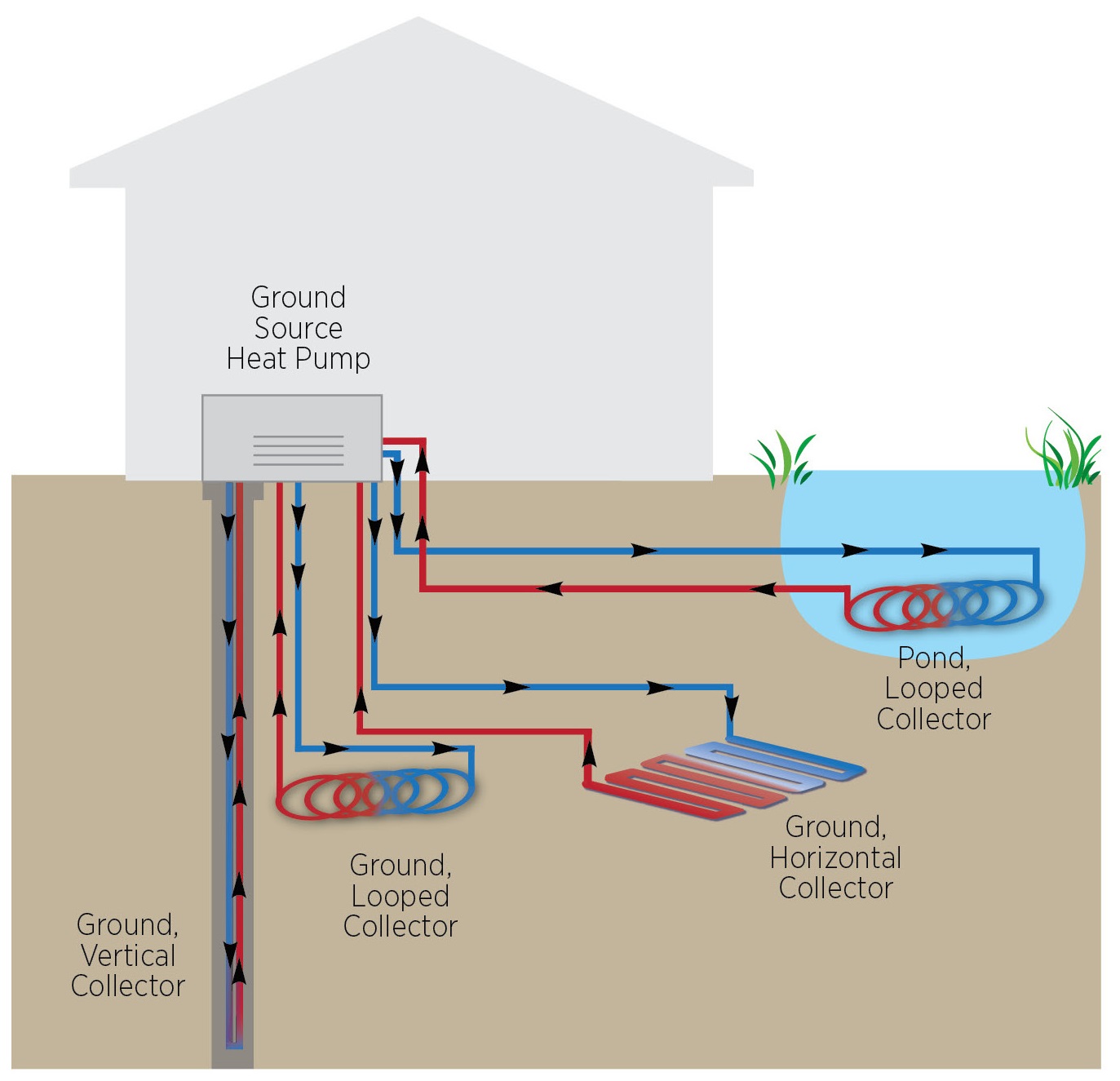
A ground-source heat pump is an electric heat pump that exchanges heat with the ground or ground water. Ground-source heat pumps (sometimes referred to as geothermal heat pumps) take advantage of the fact that the temperature of the earth below the surface remains fairly constant at a U.S. average of 55°F throughout the year (cooler in the north, warmer in the south). Because heat is exchanged with the ground rather than with the outside air, which has more erratic temperatures, ground-source heat pumps are a very efficient source of heating and cooling year round. (Note, though ground-source heat pumps are sometimes referred to as geothermal heat pumps, they should not be confused with the geothermal systems that use high below-ground temperatures associated with volcanic activity for heat and power production.)
Using the relatively stable temperatures of the ground also allows ground-source heat pumps to maintain consistent output capacities during extreme weather. This is particularly helpful during extreme heat and extreme cold events. An air-source heat pump, on the other hand, will have a significant loss or reduction in heating capacity during cold weather, and a reduction in cooling capacity during hotter weather. This is the exact opposite of what is needed at these times.
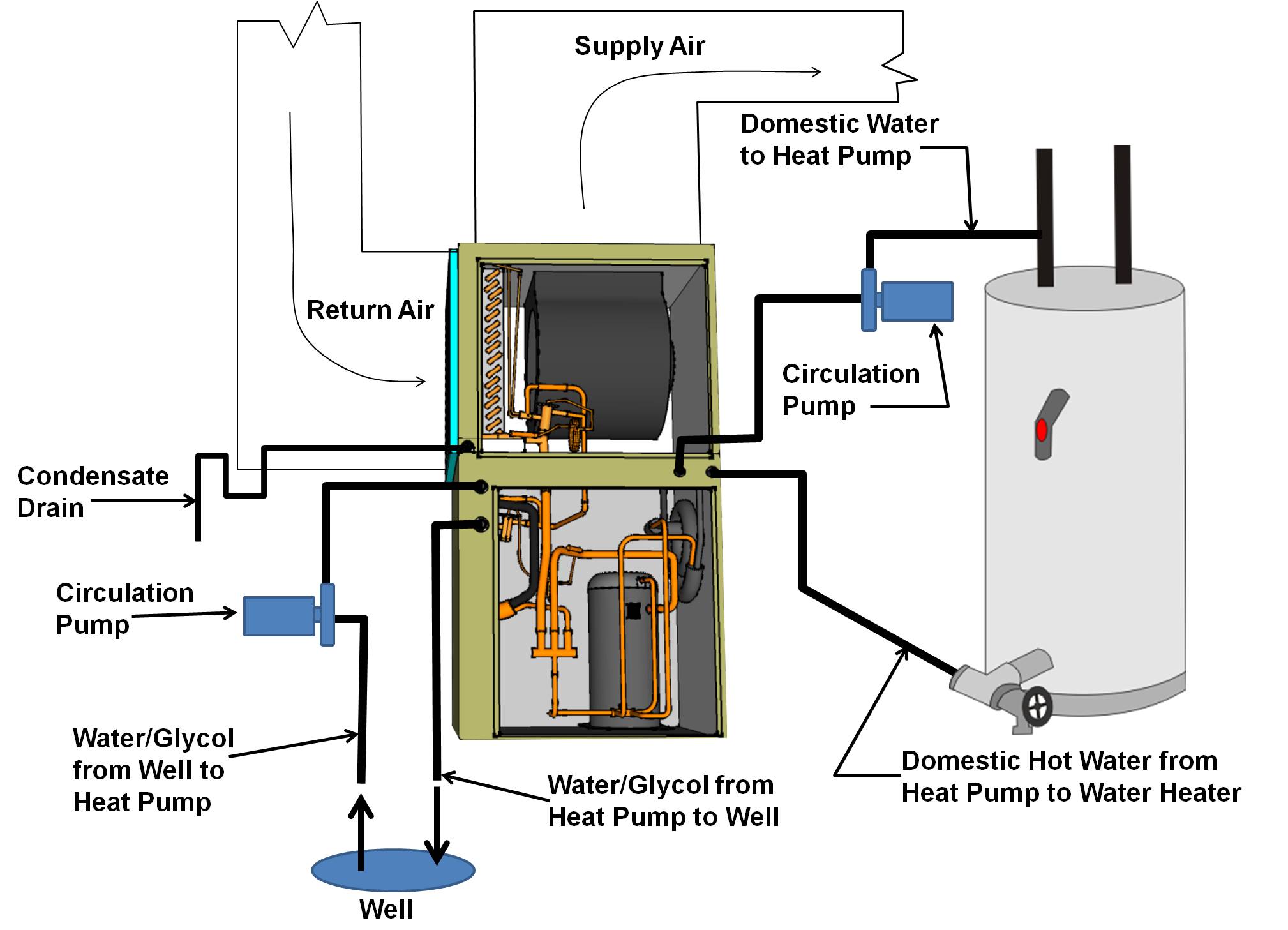
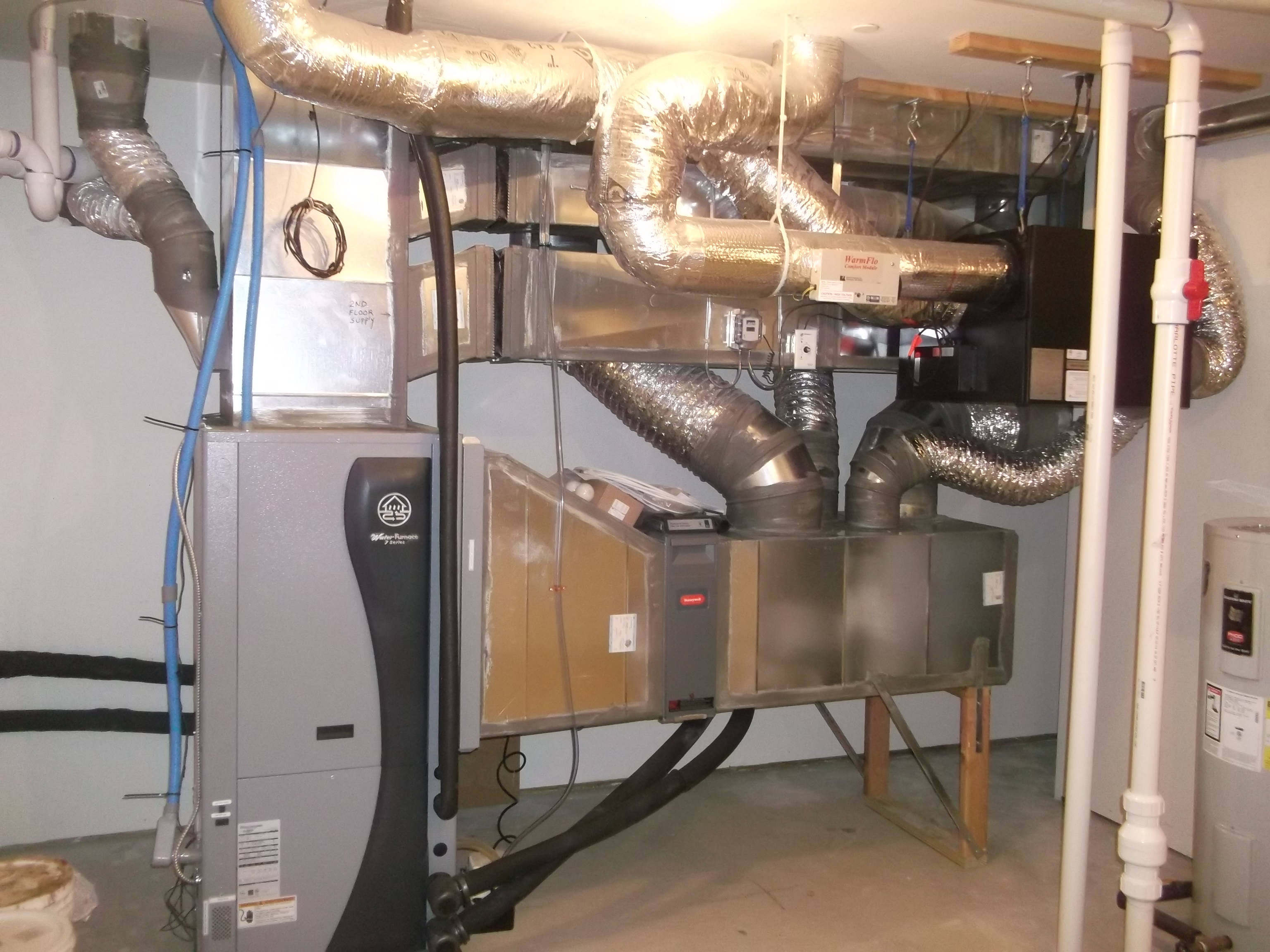
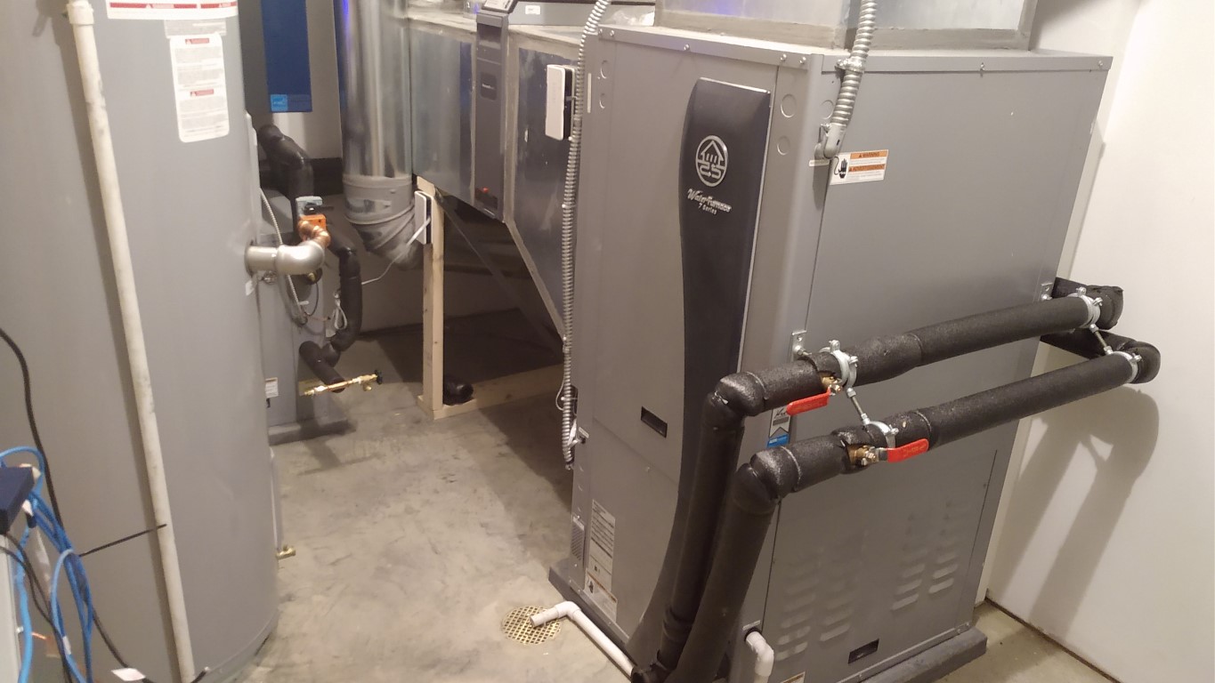
Ground-source heat pumps work by transferring heat. In heating mode, the heated fluid is transferred from the ground loop to the refrigerant loop in the heat pump. From there, a second heat exchanger transfers the heat to the home, via either warm air, which is blown over the heat exchanger and through ducts just like a central furnace, or fluid, which flows through tubing installed in the floors to provide radiant heat to the rooms.
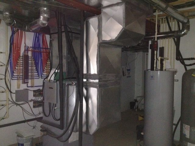
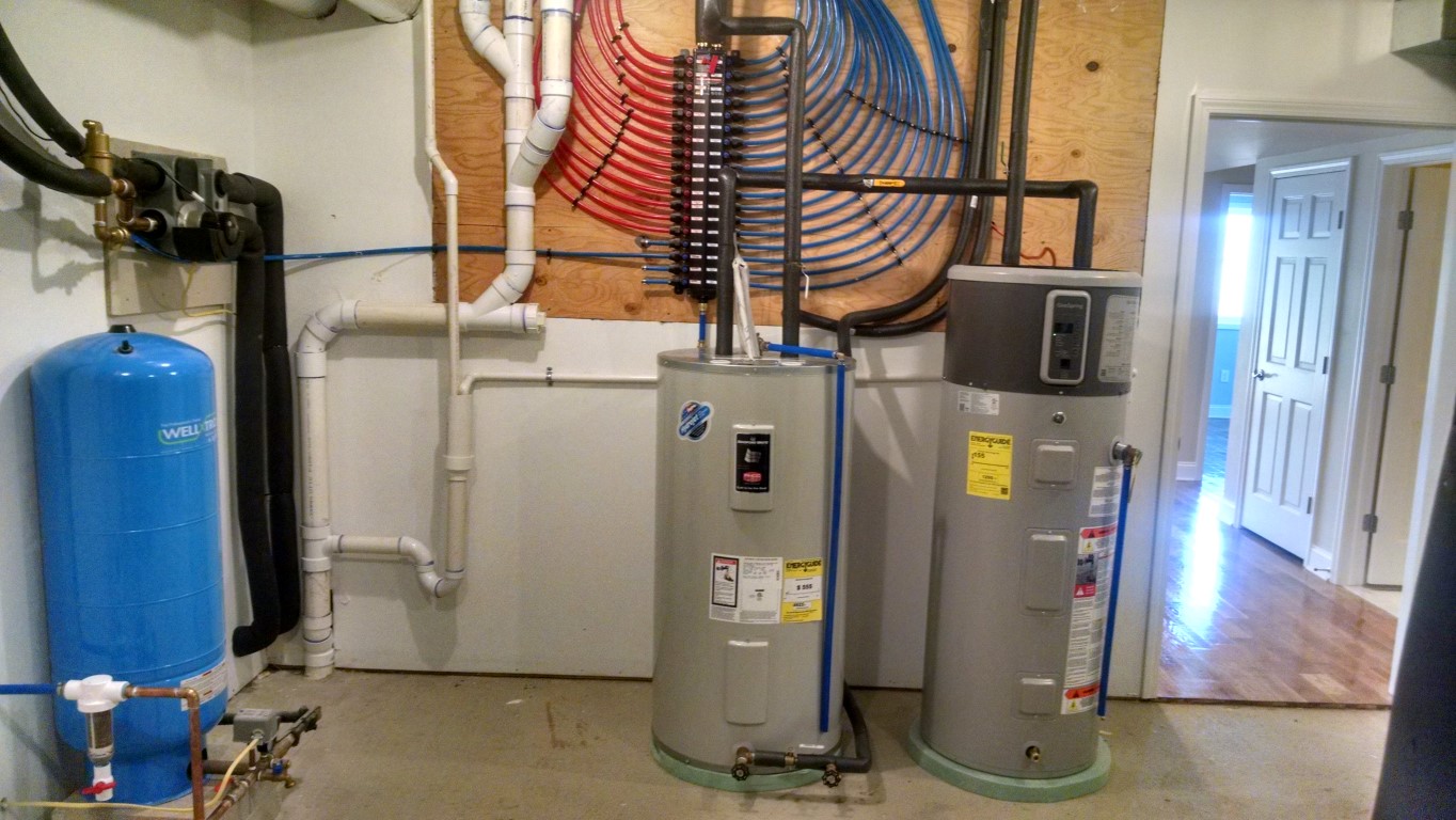
Most ground-source heat pumps are equipped with a desuperheater, which is an auxiliary heat-recovery system that can be connected to the home’s hot water tank to provide 25% to 50% of the home’s domestic hot water. Because they use extra heat from the cooling process, desuperheaters are more effective in hot climates where the heat pump is in cooling mode most of the time.
Ground-source heat pumps have risen in popularity in the United States, from 35,600 units shipped in 2000 to 115,400 ground-source heat pumps shipped in 2009. The ground-source closed-loop units shipped in 2009 had an average rated heating efficiency of 4.1 Energy Efficiency Ratio (EER) Btus/hr/W and an average rated cooling efficiency of 20.4 EER Btus/hr/W (EIA 2012).
Because fluid is a more effective heat transfer medium than air, ground-source heat pumps can have efficiencies of 300% to 600%, compared to 175% to 250% for central ducted air-source heat pumps (DOE 2012, Karr 2011). Pump power consumption is not usually included in the rated efficiency of the system and should be taken into account when considering a ground-source heat pump installation (Sherwin et al. 2010). Good thermal connectivity between the loop and the ground is essential for high efficiency and soil irregularities can affect performance. Two-speed compressors that more effectively match demand and scroll compressors with fewer moving parts have dramatically increased efficiency since the 1990s.
Because the compressor for a ground-source heat pump is located inside the home, it is subject to much less wear and tear than the outdoor compressor fan of an air-source heat pump. As a result, ground-source heat pumps last longer and maintain their efficiency better than air-source heat pumps. System life is estimated at 25 years for the inside components and 50+ years for the ground loop (DOE 2012).
Ground-source heat pumps can have high installation costs because they require drilling or trenching. If there is a pond on the property, the loops can be laid on the pond bed, a less costly installation than digging trenches, as long as the tubing is covered by 8 feet of water year-round. Recent Building America research suggests that loops might be laid within trenches dug for foundations (Christian 2008, Oklahoma State University 2011, Spitler et al. 2010). This approach could save substantially on trenching costs.
While ground-source heat pumps can save more energy than central ducted air-source-heat pump systems, studies are still being done to determine whether their additional installation costs justify their use compared to variable refrigerant flow ductless heat pumps. One option that has been proposed for increasing ground-source heat pump efficiency is combining the ground-source heat pump with the variable refrigerant flow technology of ductless heat pumps. In a modeling study of multifamily housing (using energy savings data that were confirmed by field studies), ground-source heat pumps combined with variable refrigerant flow technology cut energy use by 36% compared to an air-source central heat pump system, while ductless heat pumps alone cut energy use by 32% and a regular ground-source heat pump alone cut energy use by 28% compared to a central air source heat pump (Karr 2011).
Types of Ground-Source Heat Pump Systems
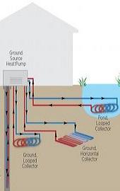
There are four basic types of ground loop systems. Three of these - horizontal, vertical, and pond/lake - are closed-loop systems. The fourth type of system is the open-loop option. Which one of these is best depends on the climate, soil conditions, available land, and local installation costs at the site. All of these approaches can be used for residential and commercial building applications (DOE 2012).
Closed-Loop Systems
Most closed-loop ground-source heat pumps circulate an antifreeze solution through a closed loop, usually made of Series 100 high-density polyethylene tubing that is buried in the ground or submerged in water. A heat exchanger transfers heat between the refrigerant in the heat pump and the antifreeze solution in the closed loop. The loop can be in a horizontal, vertical, or pond/lake configuration.
One variant of this approach, called direct exchange, does not use a heat exchanger and instead pumps the refrigerant through copper tubing that is buried in the ground in a horizontal or vertical configuration. Direct exchange systems (which are rarely installed today) require a larger compressor and work best in moist soils (sometimes requiring additional irrigation to keep the soil moist), but you should avoid installing in soils corrosive to the copper tubing. Because these systems circulate refrigerant through the ground, local environmental regulations may prohibit their use in some locations.
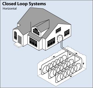
Horizontal
This type of installation is generally most cost-effective for residential installations, particularly for new construction where sufficient land is available. It requires trenches at least four feet deep. The most common layouts use two pipes, one buried at six feet and the other at four feet, or two pipes placed side-by-side at five feet in the ground in a two-foot wide trench. A third method, the Slinky™ method of overlapping coils, allows more pipe in a shorter trench, which cuts down on installation costs and makes horizontal installation possible at sites that are too small for conventional horizontal applications. A recently explored variation on horizontal placement of piping loops that could provide considerable cost savings if the ground-source heat pump is being installed in a new home under construction involves laying piping within the trenches already being dug for foundations and utility wiring and pipes (Christian 2008, Oklahoma State University 2011, Spitler et al. 2010).
Source
Online reference containing general information about geothermal heat pumps.
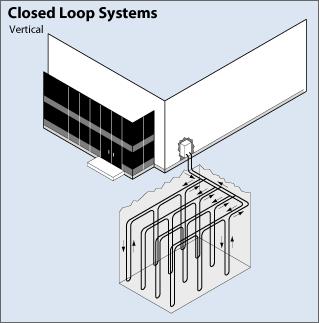
Vertical
Large commercial buildings and schools often use vertical systems because the land area required for horizontal loops would be prohibitive. Vertical loops are also used where the soil is too shallow for trenching, and they minimize the disturbance to existing landscaping. For a vertical system, holes (approximately four inches in diameter) are drilled about 20 feet apart and 100 to 400 feet deep. Into these holes go two pipes that are connected at the bottom with a U-bend to form a loop. The vertical loops are connected with horizontal pipe (i.e., manifold), placed in trenches, and connected to the heat pump in the building.
Source
Online reference containing general information about geothermal heat pumps.
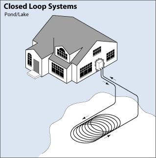
Pond/Lake
If the site has an adequate water body, this may be the lowest cost option. A supply line pipe is run underground from the building to the water and laid in coils submerged at least eight feet under the surface to prevent freezing. The coils should only be placed in a water source that meets minimum volume, depth, and quality criteria.
Source
Online reference containing general information about geothermal heat pumps.
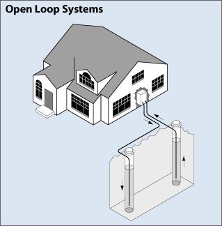
Open-Loop System
This type of system uses well or surface body water as the heat exchange fluid that circulates directly through the heat pump. Once it has circulated through the system, the water returns to the ground through a separate recharge well or surface discharge. This option is obviously practical only where there is an adequate supply of relatively clean water and all local codes and regulations regarding groundwater discharge can be met.
While open-loop systems may have lower installation costs because less drilling and excavation is involved, pumping costs are higher and water quality is a concern. Water with a high mineral content can foul the pump or the lines. A growing number of jurisdictions have outlawed open-loop systems that discharge to the surface because they may drain aquifers or contaminate wells.
Source
Online reference containing general information about geothermal heat pumps.
Hybrid Systems
Hybrid systems using several different ground-source resources, or a combination of a ground-source resource with outdoor air (i.e., a cooling tower), are another technology option. Hybrid approaches are particularly effective where cooling needs are significantly larger than heating needs. Where local geology permits, the "standing column well" is another option. In this variation of an open-loop system, one or more deep vertical wells is drilled. Water is drawn from the bottom of a standing column and returned to the top. During periods of peak heating and cooling, the system can bleed a portion of the return water rather than reinjecting it all, causing water inflow to the column from the surrounding aquifer. The bleed cycle cools the column during heat rejection, heats it during heat extraction, and reduces the required bore depth (DOE 2012).
How a Ground-Source Heat Pump Works
Source
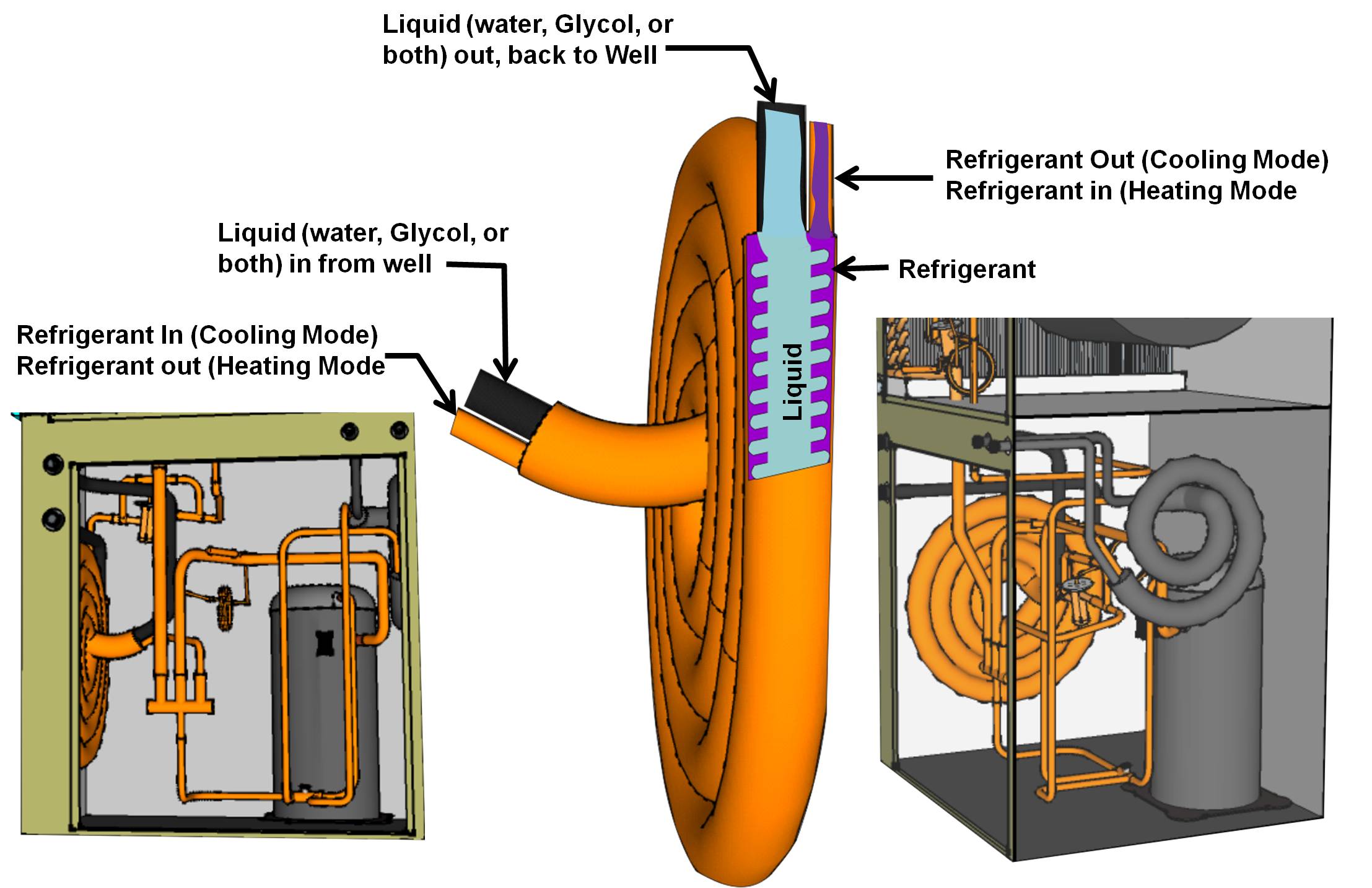
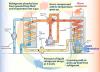
The outdoor coil in a ground-source heat pump is a tube within a tube type heat exchanger; typically referred to as a coaxial coil. Similar to air blowing over an air-to-refrigerant heat exchanger, a pump moves water, glycol, or a water-glycol mix through the inner tube of the liquid-to-refrigerant heat exchanger. The tube-within-a-tube concept of the coaxial coil provides heat transfer between the liquid and the refrigerant. Figure 6 shows the coaxial coil. Water or water/glycol flows through the center "rifled" or convoluted copper tube in a counter-flow direction to the refrigerant vapor. The refrigerant vapor flows between the convoluted tubing and the smooth outer steel tube called the shell.
Source
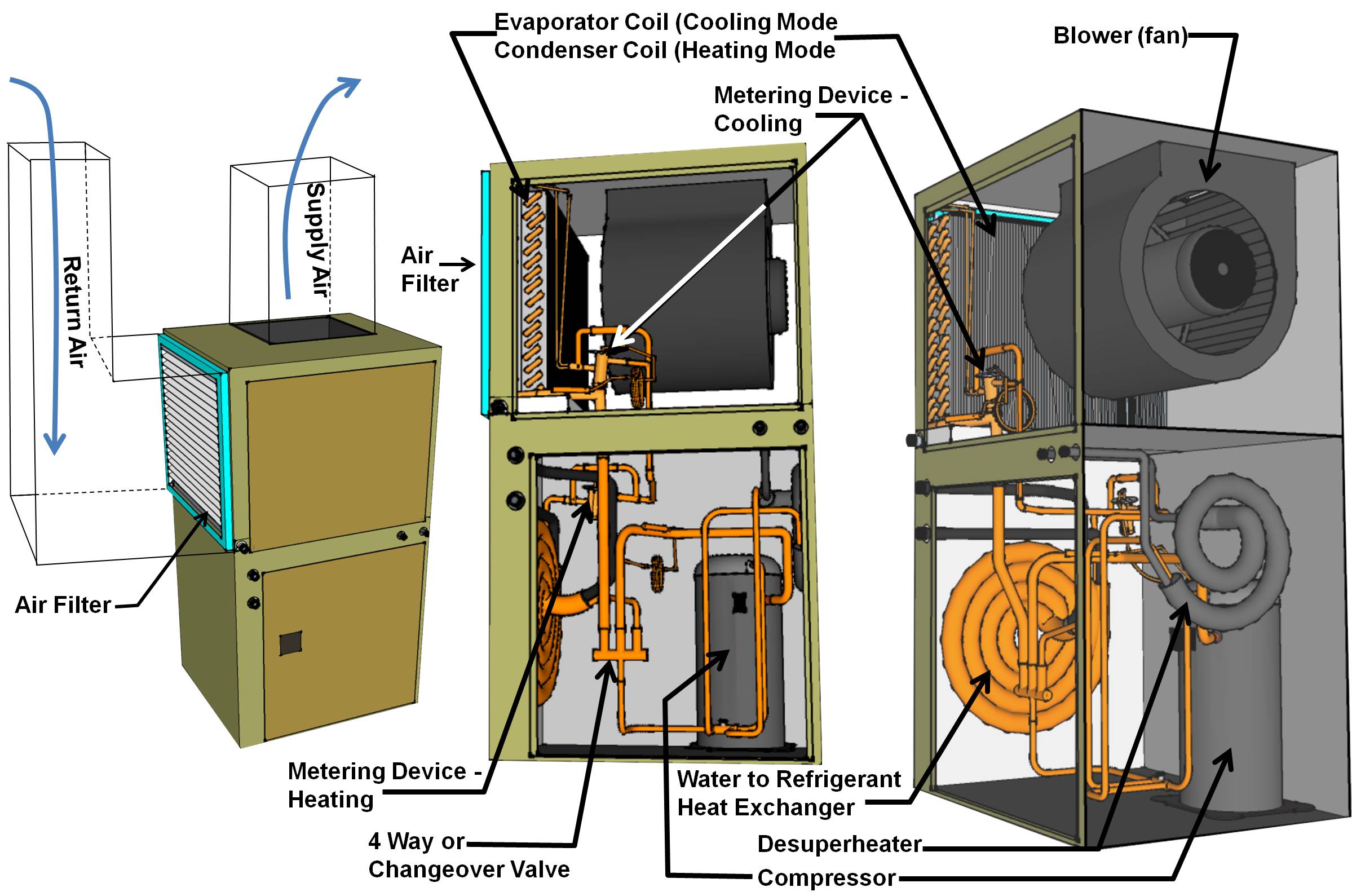
When the heat pump is in the cooling mode, super-heated refrigerant leaves the compressor and enters the changeover valve (aka four-way valve or reversing valve) where it is directed to the coaxial (outdoor) coil. Inside the coaxial coil, the refrigerant gives up its heat to the water or water-glycol mix; the refrigerant changes state from a vapor refrigerant under high pressure to a liquid refrigerant under high pressure. Before the liquid refrigerant leaves the coaxial coil, it is subcooled to about 9°F (depending on manufacturer) from the refrigerant’s relative pressure-temperature. The sub-cooled liquid refrigerant leaves the coaxial coil and enters the metering device (TXV, TEV, etc.), which meters the liquid refrigerant into the indoor coil. The metering device creates a pressure drop, allowing the liquid refrigerant to expand inside the heat exchanger, absorbing heat and changing state from a liquid back to a vapor. The vapor refrigerant leaves the indoor coil and returns to the compressor where the refrigerant vapor is compressed to a super-heated high-temperature vapor at a high pressure and the whole process begins again.
When in heating mode, the high-pressure superheated refrigerant leaves the compressor and is directed to the change-over valve; the change-over valve directs the refrigerant to the indoor coil (air-to-refrigerant heat exchanger). As the indoor fan moves cool indoor air across the indoor coil, the refrigerant in the coil gives up its heat to the indoor air thus warming the air. As the refrigerant moves through the indoor coil, it loses heat and changes state from a vapor refrigerant under high pressure to a liquid refrigerant under high pressure.
The liquid refrigerant leaves the indoor coil and enters the metering device (TXV, TEV, etc.), which meters the liquid refrigerant into the coaxial (outdoor) coil. The metering device creates a pressure drop, allowing the liquid refrigerant to expand inside the coaxial heat exchanger, absorbing heat and changing state from a liquid to a vapor refrigerant. The vapor refrigerant leaves the indoor coil and returns to the compressor where it is compressed to a super-heated high-temperature vapor at a high pressure and the whole process begins again.
Most ground-source heat pumps have a second coaxial coil that is used as a desuperheater to supply domestic hot water. The desuperheater coil is a coaxial coil much like the coaxial coil used for the outdoor coil. Figure 7 below shows the desuperheater coaxial coil to the right of the compressor. The compressor discharges superheated hot refrigerant gas, which is routed to the desuperheater. From the desuperheater, it is routed to the change-over valve (aka the four-way valve or reversing valve). The change-over valve routes the refrigerant to the coaxial (outdoor) coil if the thermostat is calling for cooling or to the indoor coil if the thermostat is calling for heating.
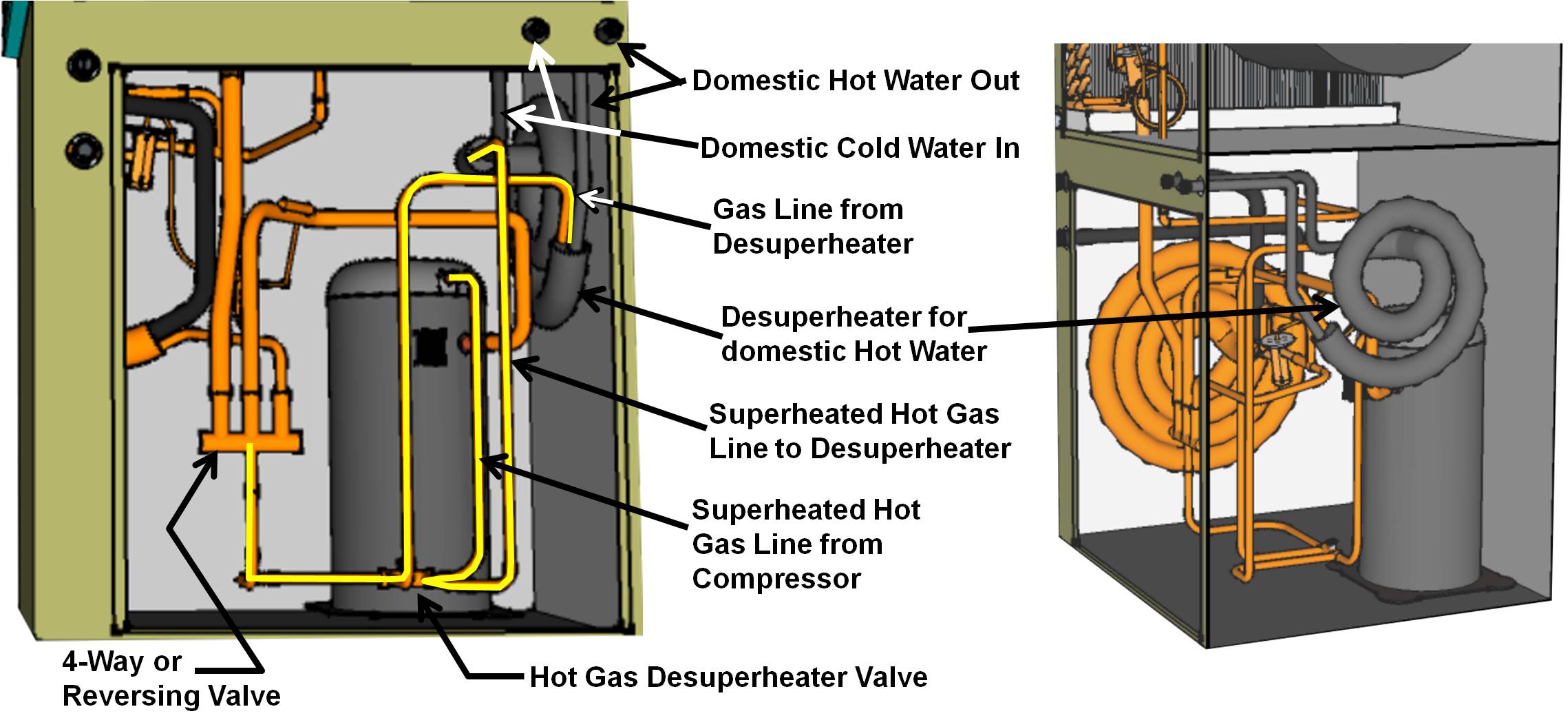
Some ground-source heat pumps that incorporate a desuperheater for domestic hot water may have a valve that is used to bypass refrigerant around the desuperheater if the water in the domestic hot water tank is up to temperature. The valve also bypasses refrigerant around the desuperheater if the discharge gas at the compressor is not hot enough to heat domestic water. The valve may be called a "hot gas desuperheater valve" or a “desuperheater diverter valve." In many systems, the valve doesn't exist and the desuperheater is directly connected to the compressor on the inlet side and the change-over valve on the outlet side. A temperature sensor is connected to the domestic water-out at the desuperheater and another sensor on the hot gas discharge line at the compressor. If the domestic hot water is hot enough or if the discharge gas from the compressor is not hot enough, the sensors turn the hot water circulating pump off.
How to Install Ground-Source Heat Pump Systems
- Select your installation type based on available space and soil type.
- Consider working with an accredited installer. The International Ground Source Heat Pump Association at Oklahoma State University accredits ground source heat pump installers (IGSHPA 2014.)
- Choose the highest performing model project costs will allow, to meet the design heating and cooling load of the project. If you are participating in an energy-efficiency program, select equipment that complies with the requirements for your climate zone, as described in the Compliance tab.
- Confirm that the indoor and outdoor components of the heat pump system match, as demonstrated by a certificate from the Air Conditioning, Heating and Refrigeration Institute (AHRI) or a copy of the catalog data provided by the original equipment manufacturer (OEM) indicating an acceptable combination.
- Properly size the equipment for the design heating or cooling load of the home (whichever is larger). Use ACCA Manual J to calculate your heating or cooling load and use ACCA Manual S to correctly size your system. This is especially important if you have done significant air sealing and insulating, which will reduce your heating and cooling load. When determining equipment sizing per ACCA Manual S, use the original equipment manufacturer (OEM)’s expanded performance table to obtain performance data at design conditions, rather than using the performance data on the AHRI certificate.
- Design an efficient air distribution system with a compact layout in accord with the ACCA Manual D. Install ducts properly for maximum airflow and efficiency in accord with ACCA Manual D. See also the Building America Solution Center guides on duct installation, insulation, and air sealing.
- Seal the open ends of the copper tubing with solder and keep them sealed at all times during the rough-in installation to prevent moisture from entering the lines.
- When the installation is completed, solder the lines closed and charge them with dry nitrogen.
- After connecting the indoor unit and the outdoor unit, vacuum the lines to 500 microns to remove air pockets.
- Follow the manufacturer’s recommendations for refrigerant charging. Too much or too little refrigerant can reduce the efficiency of the equipment and lead to premature component failures. Use the charging method recommended by the manufacturer. There are three methods for charging: the subcooling method (typically for units with a thermal expansion valve), the superheat method (typically for units with a fixed orifice), or the weigh-in method (using the refrigerant weight amount listed on the data plate on the outdoor unit). Verify that you are using the correct method for the specific heat pump model to be installed. Refrigerant charging must be done by an EPA certified technician.
- Set the time-delay relay on the unit to 30 seconds or less in humid climates to prevent moisture on the evaporator coil from evaporating back into the air stream and contributing to indoor humidity. Set the fan on the central air conditioning systems to “Auto” rather than “On” for the most efficient operation. Set the compressor to start before the blower. Make sure the drain pans are correctly installed.
- Test air flow and duct leakage.
Ensuring Success
When doing system selection do not use AHRI listed system capacity; use original equipment manufacturer expanded performance tables at design conditions. These tables should be available through the manufacturer or their representatives. For guidance on HVAC system selection, refer to Air Conditioning Contractors of America (ACCA) Manual S.
Region
For ENERGY STAR and DOE Zero Energy Ready Home climate-specific guidance, see the Compliance tab.
Factors such as the composition and properties of the soil and rock (which can affect heat transfer rates) require consideration when designing a ground loop. For example, soil with good heat transfer properties requires less piping to gather a certain amount of heat or release a certain amount heat than soil with poor heat transfer properties.
Ground temperatures differ by location. For example, the average ground temperature in Orlando, Florida is about 72°F whereas the average ground temperature in Boston, Massachusetts, is about 42°F. Ground temperatures, lot size, geology, and topography will all impact the selection of the ground source heat exchange chosen.
The map in Figure 1 shows the climate zones for states that have adopted energy codes equivalent to the International Energy Conservation Code (IECC) 2009, 12, 15, and 18. The map in Figure 2 shows the climate zones for states that have adopted energy codes equivalent to the IECC 2021. Climate zone-specific requirements specified in the IECC are shown in the Compliance tab of this guide.

Source
2012 edition of code establishing a baseline for energy efficiency by setting performance standards for the building envelope (defined as the boundary that separates heated/cooled air from unconditioned, outside air), mechanical systems, lighting systems and service water heating systems in homes and commercial businesses.

Source
2021 edition of code establishing a baseline for energy efficiency by setting performance standards for the building envelope (defined as the boundary that separates heated/cooled air from unconditioned, outside air), mechanical systems, lighting systems and service water heating systems in homes and commercial businesses.
Training
Right and Wrong Images
Source
Source
Source
Source
Source
Source
Source
Videos


Compliance
More Info
Case Studies
References and Resources
*For non-dated media, such as websites, the date listed is the date accessed.
Contributors to this Guide
The following authors and organizations contributed to the content in this Guide.
Sales
Geothermal Heat Pump = High-Efficiency or Ultra-Efficient Geo Heat Pump
Technical Description
High-efficiency and ultra-efficient geothermal or ground-source heat pumps save money by taking heat out of the ground to heat your home in the winter. In summer the cycle is reversed; they pull heat out of your home and discharge it to the ground to cool your home. Ground-source heat pumps use fluid that is carried through flexible pipes that are buried deep in the ground to transfer heat to or from the soil. The systems typically tie into a house’s duct system to deliver warm or cool air throughout the house.
Questions? Comments? Contact our webmaster.