

Scope
Provide for pressure balancing between bedrooms and the rest of the house.
- Install ducted returns or a combination of ducted returns, transfer grilles, jump ducts, and/or door undercuts in bedrooms to allow pressure balancing between bedrooms and the rest of the house in homes with ducted heating and cooling systems by providing a path for room air to return to a central air handler thereby increasing the volume of conditioned air circulating in the room.
- ENERGY STAR Single-Family New Homes requires that the dedicated return ducts, transfer grilles, jump ducts, and/or door undercuts together achieve a rater-measured pressure differential of ≥ -3 Pascals and ≤ +3 Pascals (0.012 inch water column) with respect to the main body of the house when bedroom doors are closed and the air handler is operating on the highest design fan speed. A rater-measured pressure differential of ≥ -5 Pascals and ≤ +5 Pascals (0.020 inch water column) is acceptable for rooms with a design airflow ≥150 cfm.
- If transfer grilles or jump ducts are used, refer to the balancing report provided by the HVAC contractor for the bedroom air flows to size the grilles or ducts. If a balancing report was not provided, the flow of the supply register when the air handler is on high speed may need to be measured using a flow hood, anemometer, or other flow measurement tool. Ensure that both openings have the required free area. Seal all seams, gaps, and holes in the ducts and connections.
- Test the pressure differential with the bedroom doors closed.
See the Compliance Tab for links to related codes and standards and voluntary federal energy-efficiency program requirements.
Description
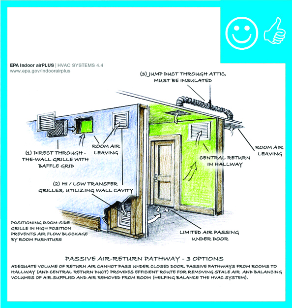
For central “forced air” furnace and air conditioning systems to operate properly, the HVAC distribution system should be designed with adequate supply and return registers to provide conditioned air to all parts of the house and return stale air to the furnace for reconditioning. Inadequate return air pathways can cause pressure imbalances from room to room, which can cause drafts and temperature differences between rooms or floors, leading to comfort complaints. Pressure imbalances can also cause the furnace and air conditioning equipment to work harder than necessary. A well-designed return air strategy is critical for the performance of the HVAC system in an energy-efficient house, which may have lower airflow requirements to meet the lower heating and cooling loads (Burdick 2011). The return air must have a clear path back to the air handler from every room that has a supply outlet, with the exception of bathrooms or kitchens due to the potential for spreading odors through the house (Burdick 2011).
Most forced air systems use central return registers consisting of one more centrally located return registers that are ducted to the return side of the air handler. To provide a pathway for air from rooms with closed doors to these central return registers, builders can use door undercuts or install transfer grilles or jump ducts. A transfer grille is a grille or register installed in the wall or above the door to connect the closed room with an open space such as a hallway or living room, thereby providing an additional pathway for stale air to reach the centrally located return.
Transfer grilles may be installed by the framer or drywaller. This task should be included in the contract for the appropriate trade depending on the workflow at a specific job site.
How to Install a Transfer Grille
Determine a location for the transfer grille on an interior wall between the frequently closed room and an open area; preferably this should be the wall where air would have the most direct path to the central return. Mark a location between two studs. Measure and cut openings in the drywall on both sides of the wall to snuggly fit the duct registers. Install the registers. Sound and light transfer between rooms can be minimized in one of the ways described below.

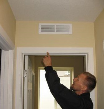
Figure 1. Installing transfer grilles is one way to balance pressures from room to room. Offset the openings from each other with the grille on the room side located high on the wall (to avoid being blocked by furniture) and the grille on the hallway side located low on the wall. The registers are offset to minimize sound and light transfer. Air flows through the uninsulated interior wall cavity.
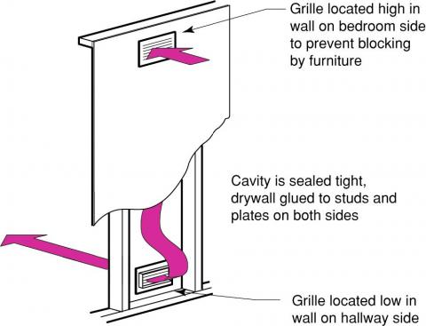
Figure 2. A transfer grille is installed in the wall to connect a closed room with an open area, thus providing an air pathway to the central return air register. The registers are offset to minimize sound and light transfer. Air flows through the uninsulated interior wall cavity.
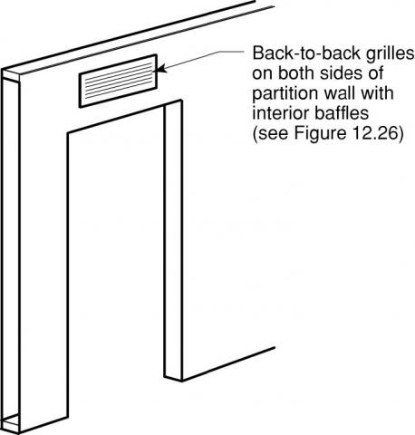
Or –- Cut the wall openings directly opposite each other and install sheet metal baffles offset from each other inside each opening to allow air passage but prevent light passage and minimize sound transfer.


Ensuring Success
To determine if an adequate pathway exists for air to return to centrally located returns, the following room-to-room pressure measurement can be used:
- Turn on the air handler to high.
- Close all interior doors.
- Using a manometer, connect tubing to the input port. The reference port for the differential pressure measurement can remain open.
- While standing in the center of the house or hallway, place the tubing from the manometer under each door and record the pressure difference from each room with respect to the main body of the house (note the presence of a negative or positive sign). The bedroom will typically be pressurized (positive) when the doors are closed.
- ENERGY STAR requires that rooms should not be pressurized or depressurized by more than 3 Pascals for any room being supplied with less than 150 cfm of conditioned air. If the supplied airflow to a room exceeds 150 cfm, a threshold of ±5 Pascals is required. These are good metrics to strive for regardless of whether or not pursuing ENERGY STAR certification.
Region
No climate specific information applies.
Training
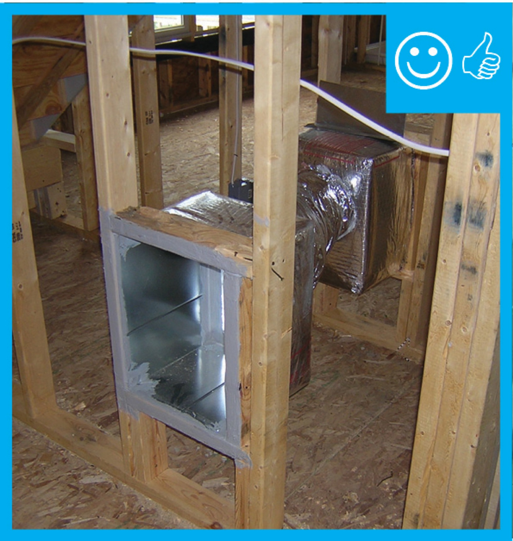
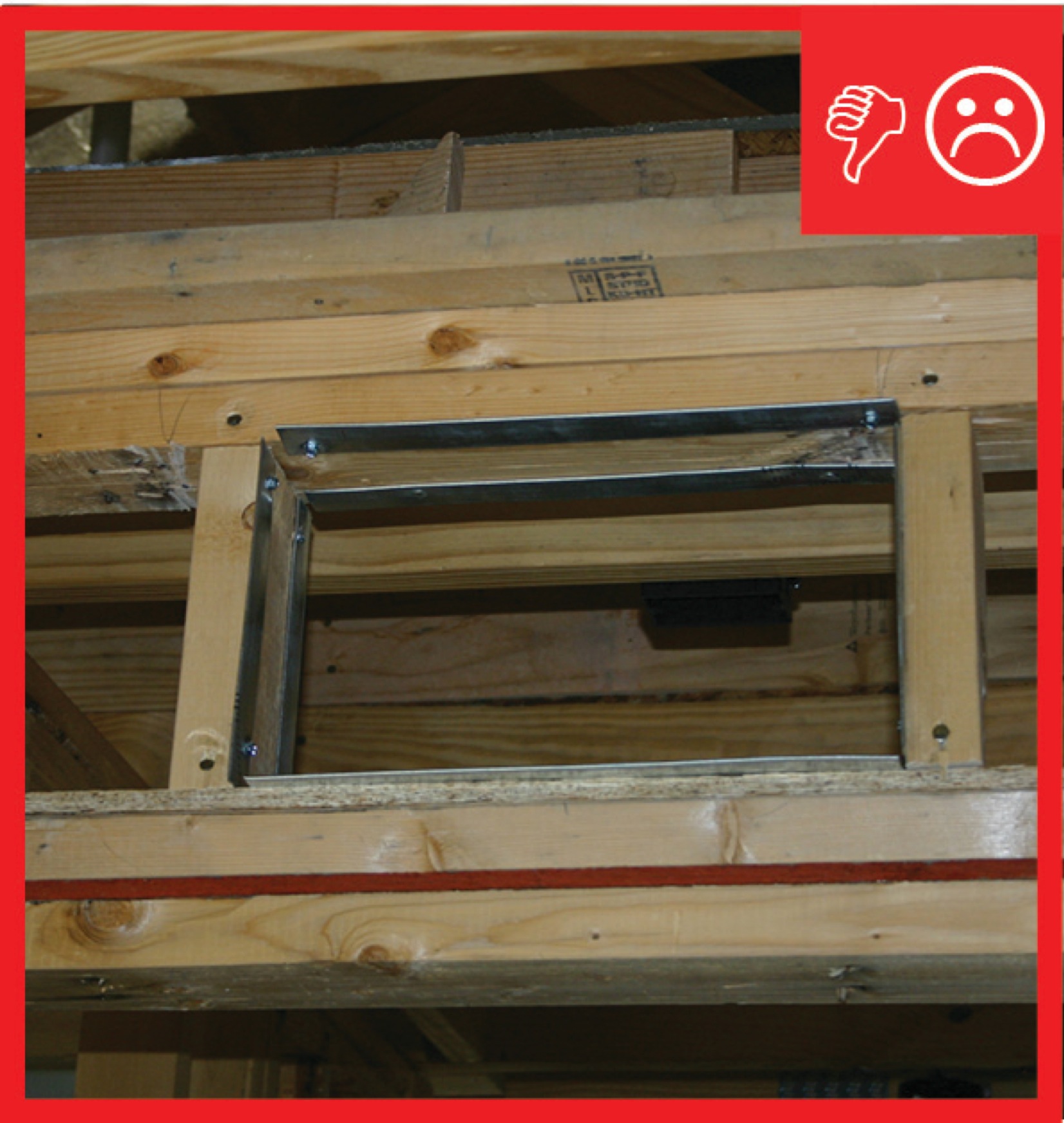
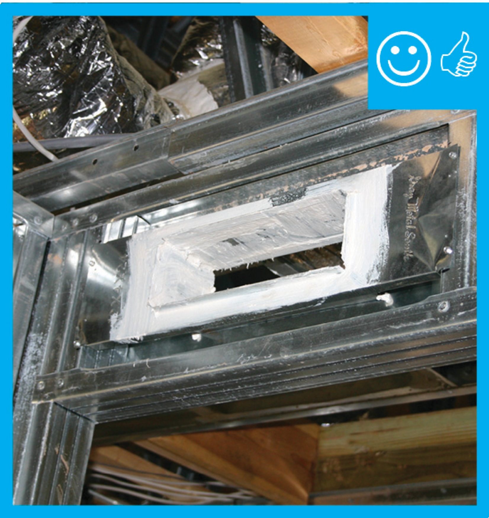
Right and Wrong Images
Source
Source
Website providing the technical specifications and related documents for home builders, subcontractors, architects, and other housing professionals interested in certifying a home to the EPA's Indoor airPLUS program requirements.
Source
Source
Videos
Compliance
Retrofit
SCOPE
Install transfer grilles to address pressure differences in an existing home.
- Test pressure differences between rooms as part of an energy assessment or in response to complaints about uneven temperatures or drafts.
- Inspect for adequate return pathways to the central air handler (central return duct and air pathways to the central return from isolated rooms [i.e., bedroom and office rooms with doors that are often shut]). Return pathways can be provided by individual return ducts, transfer grilles, jump ducts, or door undercuts.
- Install ducted returns or other return pathways as needed.
DESCRIPTION
In existing homes, homeowners may sometimes experience strong drafts or large temperature differences between rooms or central forced air systems that seemed to be noisier or working harder than they need to. One cause of these problems could be pressure differences between rooms, especially when doors are closed, caused by inadequate return air pathways to allow stale air to flow freely back to the return side of the HVAC air handler so it can be heated or cooled for distribution back through the house. Pressure testing as part of a whole-house energy assessment can determine whether the house is pressures are unbalanced. For more information on pressure balancing, see the guide Pressure Balancing Supply and Return Ducts in Existing Homes.
There are several methods that can be used to provide return pathways from isolated rooms to the central return grille; these include individual return ducts, transfer grilles, jump ducts, or door undercuts.
In existing homes, transfer grilles will typically be installed as direct through-the-wall transfers. High-low transfer grille configurations are better able to minimize sound and light transfer but they require a more destructive/intrusive installation. However, there are some grille insert options for through-wall transfers that minimize sound and light transfer. A good rule of thumb is to provide a grille-free area (this is not the grille size, but the available opening area of the grille) of ≥1 square inch for each cubic feet per minute of supply air to a room.
How to Install a Transfer Grille in an Existing Wall:
- Verify location of studs over the door or other area where a transfer grille is to be placed. A stud finder can be useful for this task.
- Measure the transfer grille frame dimensions and transfer this onto the wall surface. Use a bubble level to properly align the frame outline.
- Cut through the wall board. You will need to be careful not to cut or disturb wiring or pipes in the wall assembly. This may require careful exploration into the wall cavity before cutting the full opening required for the transfer grille. If you have an attic above the interior wall or a basement below the wall, one way to confirm the existence of wiring and piping in the stud bay in which a transfer grille is to be installed is to check the top plate or sill plate to see if any wires or plumbing pipes are entering the framed bay. Still, be aware that electrical wires typically run around a room parallel with the floor, so be mindful of the location of electrical outlets and fixtures for potential clues to the location of the wiring. It is also a good idea to shut off the electrical circuit in the area in which you are working as an additional precaution. Also be aware of where the water line shut-off is prior to beginning any work in the walls.
- Set the frame in place and trace the outline on the backside of the adjoining wall.
- Cut through the opposite wall.
- Depending on the transfer grille unit, you may have another frame to slide into the opening from the opposite side.
- Secure the grille faces using screws.
See the Training tab for videos showing how to install transfer grilles.
If cutting through painted surfaces, check for lead paint and mitigate as required. If cutting through plaster and wood lath walls, additional care will be required to minimize crumbling of the plaster. High-speed cutting tools, such as powered multi-tools or an angle grinder with a diamond blade, can assist in making clean cuts through the plaster and lath (but will create a considerable amount of dust, so you may want to have a vacuum operating next to the tool while cutting. Another trick is to apply painter’s tape on the wall prior to marking off the area to cut on the tape. This can help control crumbling of the plaster during the cut.
When doing work in the walls of an existing home, see the following Building America Solution Center guide for safety guidelines:
Also see the U.S. Department of Energy's Standard Work Specifications guidance for general worker safety.
COMPLIANCE
See Compliance Tab.
More Info
Case Studies
Contributors to this Guide
The following authors and organizations contributed to the content in this Guide.
Building Science Corporation, lead for the Building Science Consortium (BSC), Steven Winter Associates, Inc., lead for the Consortium for Advanced Residential Buildings (CARB), both DOE Building America Research Teams, and the Pacific Northwest National Laboratory
Sales
Transfer Grills = Comfort Vent
Technical Description
Air needs to flow from the central comfort system to living spaces and back again. Comfort vents allow air to flow from each bedroom to central return ducts often located in hallways. The vents are designed for effective air flow while providing visual privacy with grills and acoustic privacy with baffles.
Questions? Comments? Contact our webmaster.