

Scope
Provide for pressure balancing between bedrooms and the rest of the house.
- Install ducted returns or a combination of ducted returns, transfer grilles, jump ducts, and/or door undercuts in bedrooms to allow pressure balancing between bedrooms and the rest of the house in homes with ducted heating and cooling systems by providing a path for room air to return to the central air handler, thereby increasing the volume of conditioned air circulating in the room.
- Do not use building cavities alone for return air pathways. Return pathways should be ducted from the return grille to the return plenum of the central air handler. The return ducts should be sealed with mastic or metal tape at all seams and joints.
- ENERGY STAR Single-Family New Homes requires that the dedicated return ducts, transfer grilles, jump ducts, and/or door undercuts together achieve a rater-measured pressure differential of ≥ -3 Pascals and ≤ +3 Pascals (0.012 inch water column) with respect to the main body of the house when bedroom doors are closed and the air handler is operating on the highest design fan speed. A rater-measured pressure differential of ≥ -5 Pascals and ≤ +5 Pascals (0.020 inch water column) is acceptable for rooms with a design airflow ≥150 cfm.
- Refer to the balancing report provided by the HVAC contractor for the bedroom air flows to size the return ducts. If a balancing report was not provided, the flow of the supply register when the air handler is on high speed may need to be measured using a flow hood, anemometer, or other flow measurement tool.
- Test the pressure differential with the bedroom doors closed.
See the Compliance Tab for links to related codes and standards and voluntary federal energy-efficiency program requirements.
Description
For central “forced air” furnace and air conditioning systems to operate properly, the HVAC distribution system should be designed with adequate supply and return registers to provide conditioned air to all parts of the house and return stale air to the furnace for reconditioning. Inadequate return air pathways can cause pressure imbalances from room to room, which can cause drafts and temperature differences between rooms or floors, leading to comfort complaints. Pressure imbalances can also cause the furnace and air conditioning equipment to work harder than necessary. A well-designed return air strategy is critical for the performance of the HVAC system in an energy-efficient house, which may have lower airflow requirements to meet the lower heating and cooling loads (Burdick 2011). The return air must have a clear path back to the air handler from every room that has a supply outlet, with the exception of bathrooms or kitchens due to the potential for spreading odors through the house (Burdick 2011).
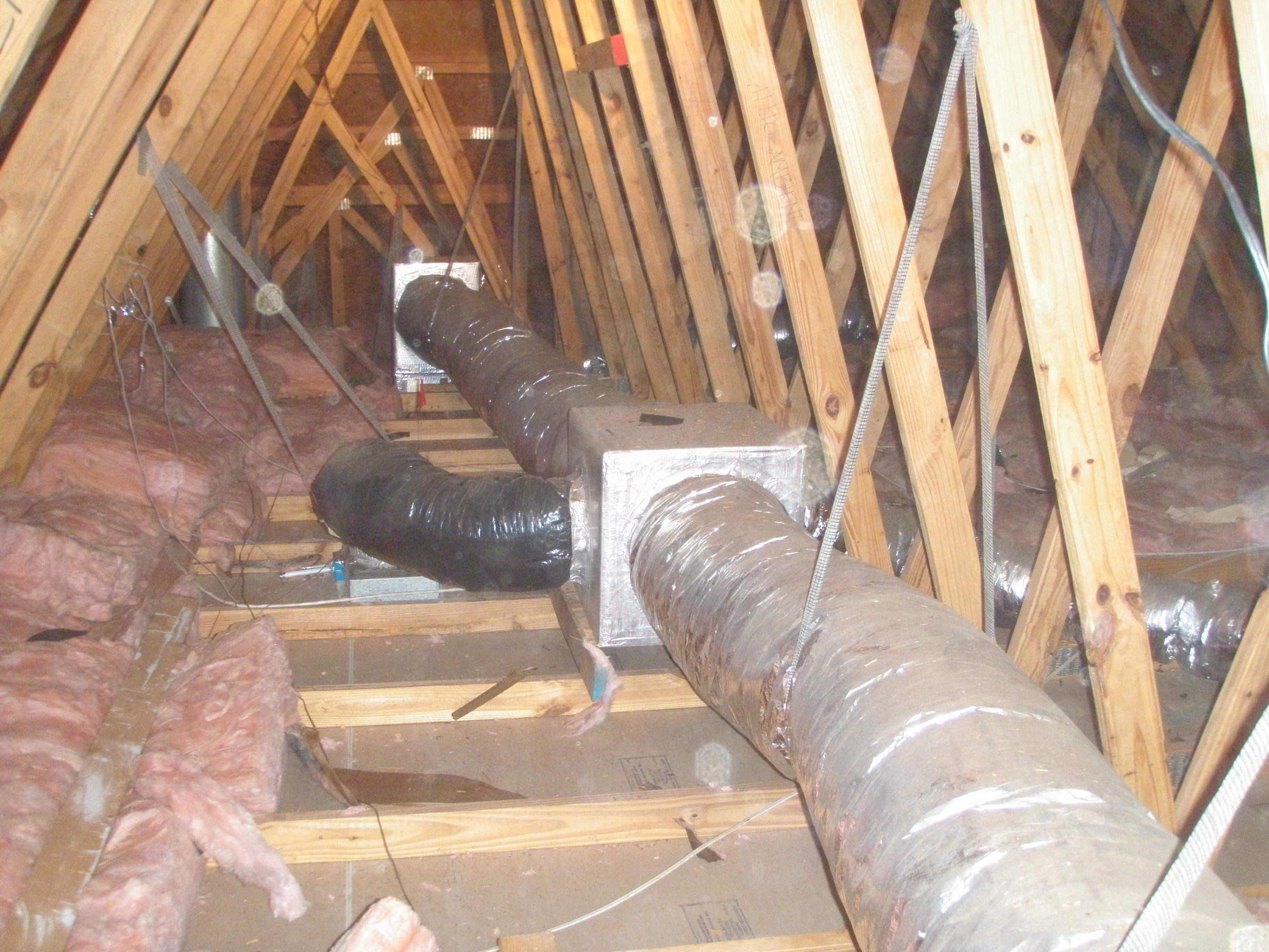
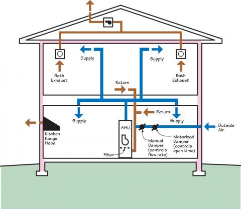
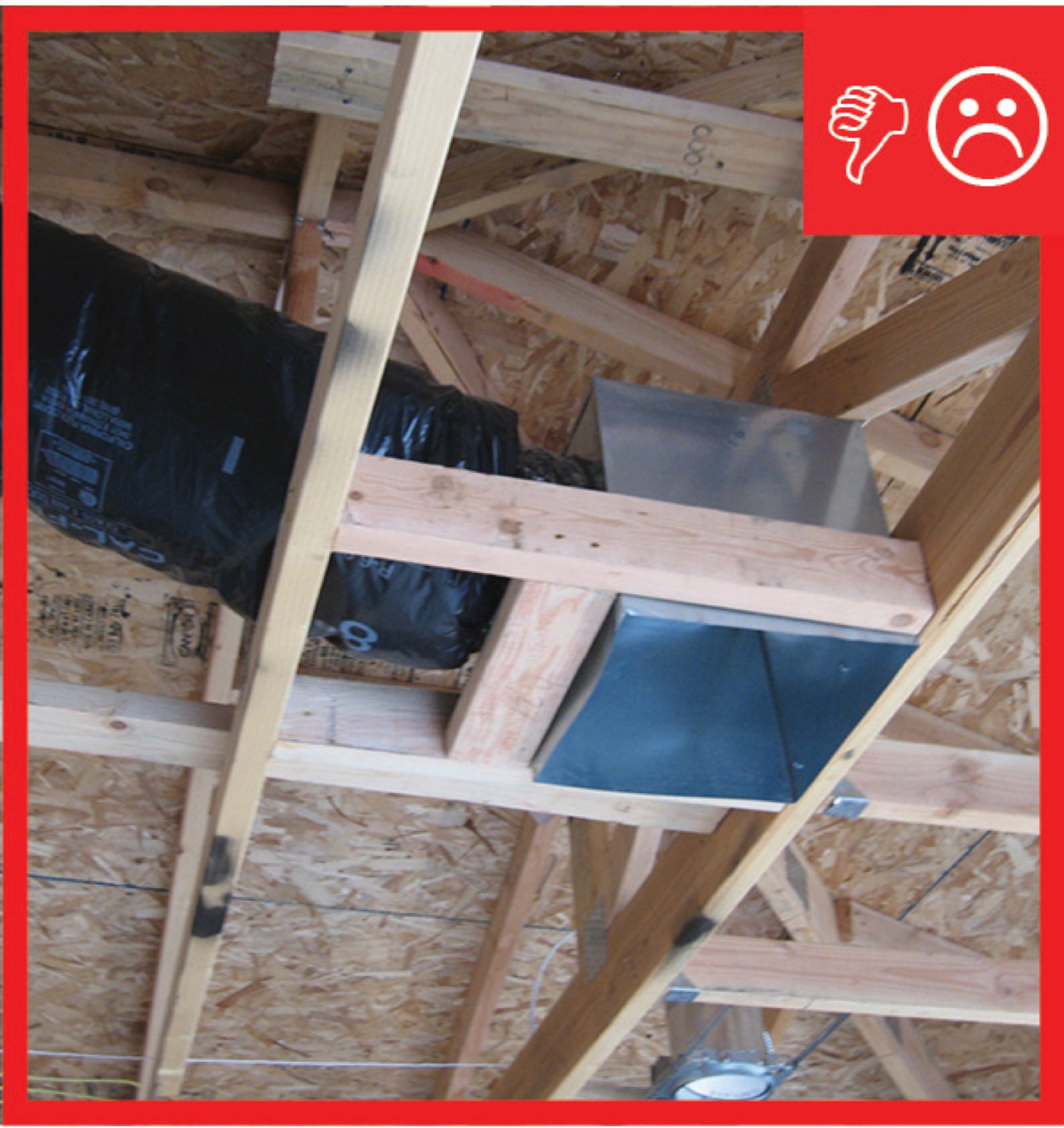
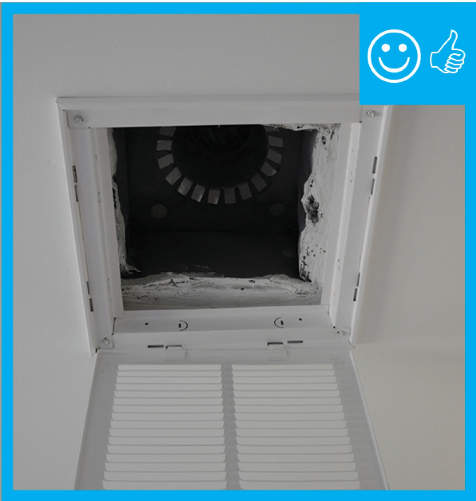
Each room can be individually ducted to the return side of the air handler; however, installing that much ducting is costly and there may be space constraints that limit the feasibility of this approach. Utilizing a central return strategy is a simple and effective way to return stale air to the air handler (Figure 1). When utilizing a central return strategy, one or more return registers should be installed in central hallways or stairwells adjacent to the main living spaces of the house, with at least one return per floor. These central returns should be ducted to the return side of the HVAC air handler with air-sealed ducts that are insulated if located in unconditioned space (Figure 2). Building cavities (the space between wall studs or “panned” floor joists) should not be used as return air pathways; if unducted, these spaces are very difficult to air seal. Return air pathways that leak will draw air from unintended places in the house and can lead to undesirable pressure differences. A fully ducted return system will be easier to air seal and will have better airflow characteristics than building cavities used as return air pathways.
To ensure that “stale” air is able to return to these central returns from rooms that have closeable doors such as bedrooms or offices, builders will often rely on door undercuts. Typical door undercuts (1/2 to 3/4 inch) alone do not allow adequate return volume, especially when carpet is installed, and are not appropriate for an energy-efficient house. Door undercuts are not approved in ACCA Manual D (Rutkowski 2009). Other methods for providing an air pathway from closed rooms to central return registers are jump ducts and transfer grilles.
Return ducts are installed by the HVAC contractor. Return duct locations should be indicated on the HVAC design plans. Tasks associated with this installation should be included in the contract for the appropriate trade, depending on the workflow at a specific job site.
How to Install Return Ducts
- Calculate the amount of return air needed. A target value for return capacity is two times the volume of the total supply air with an airflow velocity within the return of less than 500 feet per minute and the net free area of the grille sized 1.5 times the cross-sectional area of the return duct (Burdick 2011). ENERGY STAR requires that returns achieve a rater-measured pressure differential ≥ -3 Pascals and ≤ +3 Pascals (0.012 inch water column) with respect to the main body of the house when bedroom doors are closed and the air handler is operating on the highest design fan speed. A Rater-measured pressure differential of ≥ -5 Pascals and ≤ +5 Pascals (0.020 inch water column) is acceptable for rooms with a design airflow ≥150 cfm. The bedrooms can be pressure-balanced using any combination of transfer grilles, jump ducts, dedicated return ducts, and/or undercut doors.
- Determine whether you will use individual return ducts to each bedroom, one or more central ducts, or central ducts in combination with transfer grills, jump ducts, and/or undercut doors. Consider filter placement when making this decision. With individually ducted returns, the filter will need to be located at the equipment return air inlet. With a centrally located return, the filter can be located at the return grille. This configuration may make it easier for the homeowner to change or clean the furnace filter, if plans called for locating the furnace in a hard to reach location, such as an attic or crawlspace.
- Consider noise when determining placement of returns. A return duct that has a direct connection to the blower motor could transfer that blower noise to the living room.
- Consider size when locating central returns. Central return grilles are much larger than most supply grilles.
- Install return ducts as you would supply ducts.
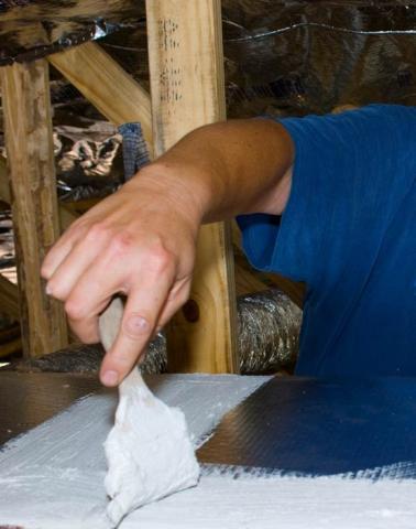
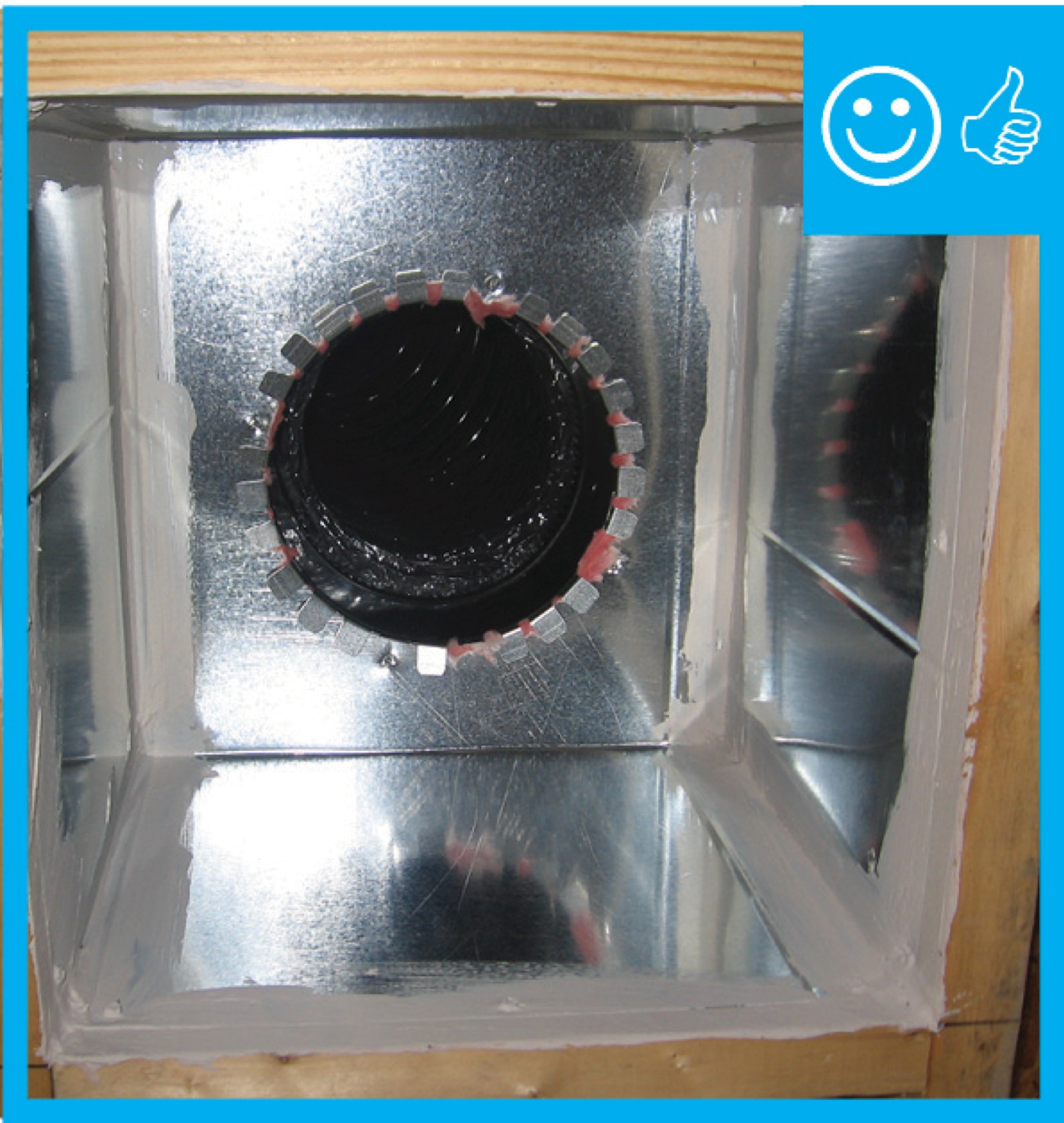
- Seal all seams, gaps, and holes of the return duct system with mastic (Figure 3).
- Seal the return box to the floor, wall, or ceiling with mastic, caulk, and/or foam.
- Do not use building cavities as return air pathways.
Source
Ensuring Success
To determine if an adequate pathway exists for air to return to centrally located returns, the following room-to-room pressure measurement can be used:
- Turn on the air handler to high.
- Close all interior doors.
- Using a manometer, connect tubing to the input port. The reference port for the differential pressure measurement can remain open.
- While standing in the center of the house or hallway, place the tubing from the manometer under each door and record the pressure difference from each room with respect to the main body of the house (note the presence of a negative or positive sign). The bedroom will typically be pressurized (positive) when the doors are closed.
- ENERGY STAR requires that rooms should not be pressurized or depressurized by more than 3 Pascals for any room being supplied with less than 150 cfm of conditioned air. If the supplied airflow to a room exceeds 150 cfm, a threshold of ±5 Pascals is required. These are good metrics to strive for regardless of whether or not pursuing ENERGY STAR certification.
Region
No climate specific information applies.
Training
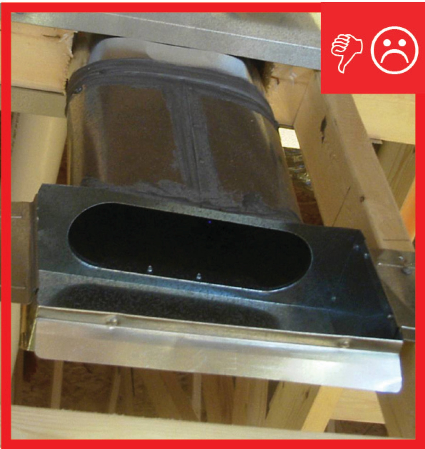
Right and Wrong Images
Videos
Compliance
Retrofit
SCOPE
Install ducted returns to address pressure differences in an existing home.
- Test pressure differences between rooms as part of an energy assessment or in response to complaints about uneven temperatures or drafts.
- Inspect for adequate return pathways to the central air handler (central return duct and air pathways to the central return from isolated rooms [i.e., bedroom and office rooms with doors that are often shut]). Return pathways can be provided by individual return ducts, transfer grilles, jump ducts, or door undercuts.
- Install ducted returns or other return pathways as needed.
DESCRIPTION
In existing homes, homeowners may sometimes experience strong drafts or large temperature differences between rooms or central forced air systems that seemed to be noisier or working harder than they need to. One cause of these problems could be pressure differences between rooms, especially when doors are closed, caused by inadequate return air pathways to allow stale air to flow freely back to the return side of the HVAC air handler so it can be heated or cooled for distribution back through the house. Pressure testing as part of a whole-house energy assessment can determine whether the house is pressures are unbalanced. For more information on pressure balancing, see the guide Pressure Balancing Supply and Return Ducts in Existing Homes.
There are several methods that can be used to provide return pathways from isolated rooms to the central return grille; these include individual return ducts, transfer grilles, jump ducts, or door undercuts.
The steps to install ducted returns are the same as with new construction methods. Access to the attic or basement may be required. While it is not desirable to locate ducts in unconditioned spaces (e.g., a vented attic), if that is where they are already located, it may be beyond the budget of the retrofit project to move them into conditioned space. In this case, insulate the ducted returns to or above new code requirements to minimize the negative impacts (heat loss/gain to unconditioned space). It may be possible to bury the ductwork under the attic insulation and/or to encapsulate the ductwork with spray foam to minimize the impact of locating the ducts in unconditioned spaces.
If cutting through painted surfaces, check for lead paint and mitigate as required. If cutting through plaster and wood lath ceilings, additional care will be required to minimize crumbling of the plaster. High-speed cutting tools, such as powered multi-tools or an angle grinder with a diamond blade, can assist in making clean cuts through the plaster and lath (but will create a considerable amount of dust, so you may want to have a vacuum operating next to the tool while cutting. Another trick is to apply a sealing compound to the attic side of the lath to harden it up (minimize flex) prior to cutting.
When doing work in an existing home, refer to the following Building America Solution Center guides for safety guidelines:
- Pre-Retrofit Assessment of Attics, Ceilings, and Roofs
- Pre-Retrofit Assessment of Crawlspaces and Basements
- Pre-Retrofit Assessment of Hazardous Materials
Also see the U.S. Department of Energy's Standard Work Specifications guidance for general worker safety.
COMPLIANCE
See Compliance tab.
More Info
Case Studies
References and Resources
*For non-dated media, such as websites, the date listed is the date accessed.
Contributors to this Guide
The following authors and organizations contributed to the content in this Guide.
- IBACOS, lead for IBACOS, a DOE Building America Research Team
- Steven Winter Associates, Inc., lead for the Consortium for Advanced Residential Buildings (CARB), a DOE Building America Research Team.
- Pacific Northwest National Laboratory
Sales
Ducted Returns

Technical Description
Comfort systems use fans to push heated and cooled air through ducts into living spaces. Air also needs a way to circulate back to the central comfort system equipment, where it again gets heated or cooled and circulated back to the living spaces. Most homes use centrally located return ducts to capture and return air back to the central comfort system. In contrast, a comfort return system uses separate ducts in each major room to capture and deliver air back to the central comfort system.
Questions? Comments? Contact our webmaster.