

Scope
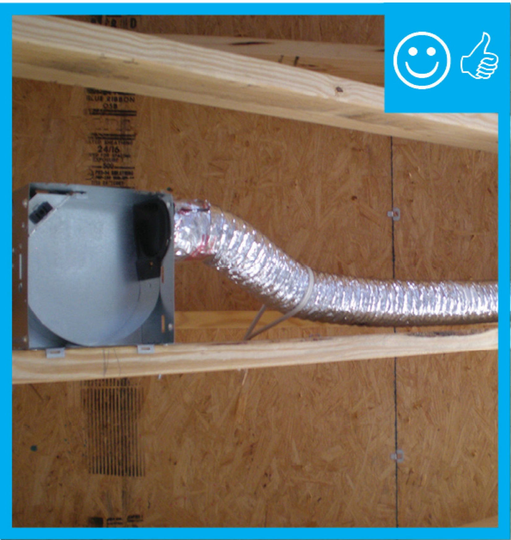
Install ducts without excessive coiled or looped flexible ductwork.
- Consider duct layout in the initial framing design stage to plan for short, straight duct runs wherever possible.
- Install flex duct in the straightest line possible; pull ducting taut and provide adequate supports per code.
- Ensure that the radius of each bend is no less than the diameter of the flexible duct.
- Coordinate with the plumber and the electrician to avoid crushing ducts when other services are installed.
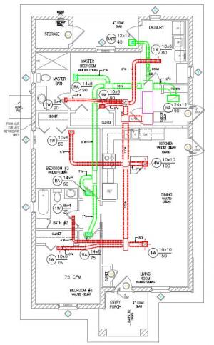
- Design ducts in compliance with Manual D.
- Use proper sized ducts or balancing dampers rather than loops in flex ducts to control air flow. For metal ducts, butterfly dampers may be used to control air flow.
- To prevent kinks at the duct and boot connections, consider using metal duct elbows instead of flex duct.
See the Compliance Tab for links to related codes and standards and voluntary federal energy-efficiency program requirements.
Description
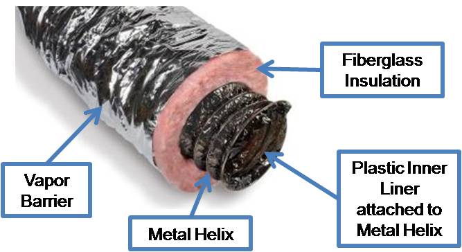
Flexible duct, known as flex duct, is very convenient ducting for attaching supply air outlets to rigid trunk ductwork, and, in many cases, flex duct comprises the entire duct system. Flex duct made for HVAC applications is typically constructed of a plastic inner liner attached to a metal wire helix (or coil) to make round, flex duct. The duct comes with a layer of fiberglass blanket insulation already attached around the duct. The insulation is covered and protected by a polyethylene or foil vapor barrier. Flex duct is typically available in insulation values of R-4, R-6, and R-8. For residential HVAC systems, insulated flex duct typically comes in diameters of 4 inches through 10 inches; above 10 inches, it comes in even sizes of 12, 14, 16, etc., up to 22 inches measured at the radius of the metal helix.
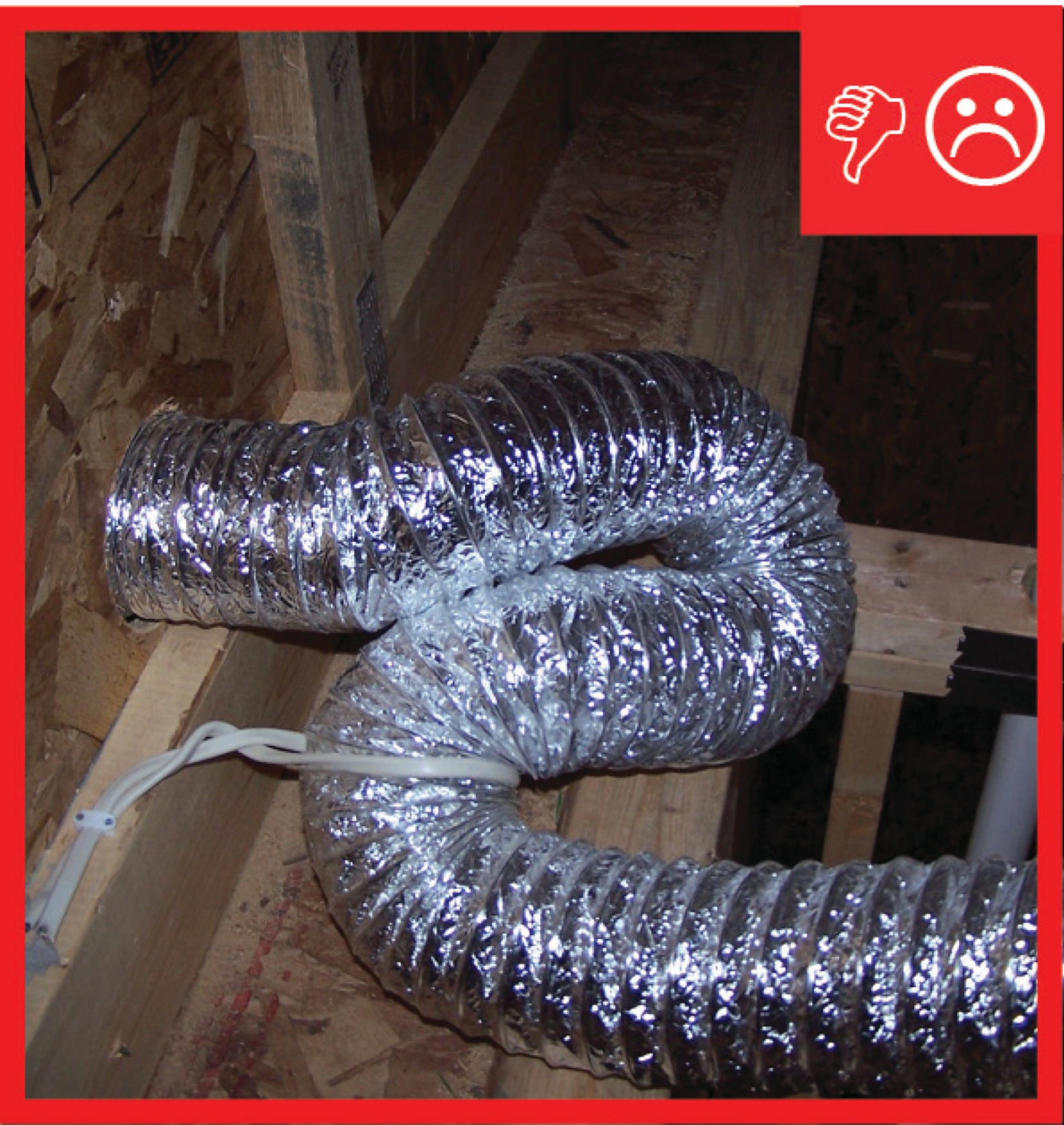
Duct runs should be as short and straight as possible and flex duct should be stretched taut before connecting for maximum efficiency and air flow volume. Sloppy installation with flex ducts that loop, coil, or sag excessively adds to the pressure drop across the entire duct system and wastes materials. Some contractors intentionally loop the flexible duct as a way to decrease airflow to a particular room; however, decreases in airflow should be handled with dampers instead as stated in the ENERGY STAR Version 3.0/3.1 National HVAC Commissioning Checklist, footnote 5: "Air balancing of supply registers and return grilles is highly recommended to improve the performance of the HVAC system and comfort of the occupants, but is not required at this time for certification. When air balancing is completed, balancing dampers or proper duct sizing shall be used instead of looped or coiled ductwork to limit flow to diffusers. When balancing dampers are used, they shall be located at the trunk to limit noise unless the trunk will not be accessible when the balancing process is conducted. In such cases, Opposable Blade Dampers (OBD) or dampers located in the duct boot are permitted to be used."
Manual D Residential Duct Systems (ACCA 2009) sets standards for flex duct design and installation. See Appendix 17 for a detailed discussion of duct installation. The Flexible Duct Performance Standards (Fifth Edition) by the Air Diffusion Council (ADC) provides guidance to designers, architects, engineers, contractors, and installers.
For more on flex duct installation, see No Kinks or Sharp Bends in Flex Duct Installation, Sufficient Cavity Space for Flex Ducts, Support at Intervals for Flex Ducts and Sealed and Insulated Flex Ducts.
How to Install Flex Duct without Excessive Looping
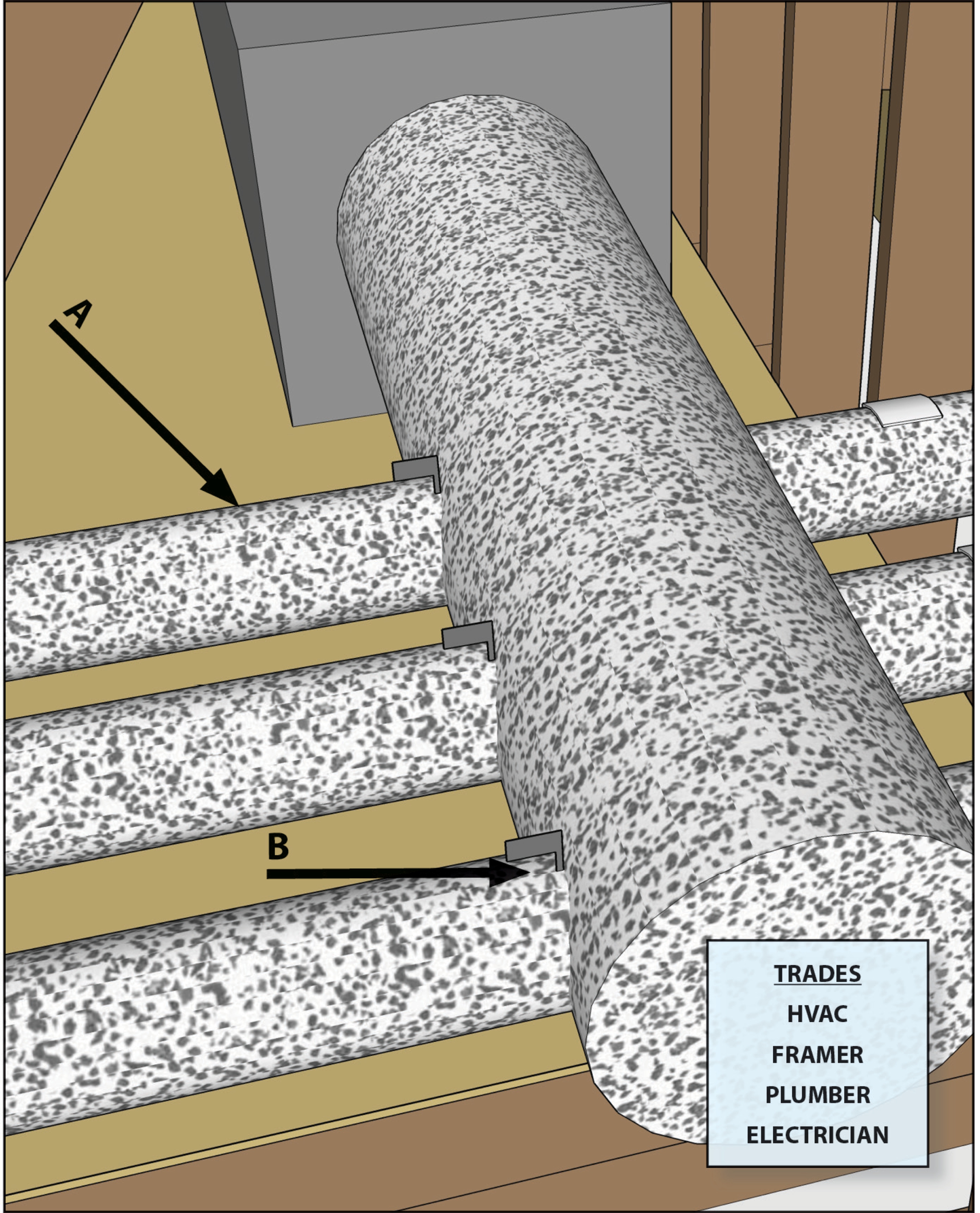
Plan for duct runs in the initial house design, especially the framing plan, so that the duct layout is short and straight with ducts resting on ceiling rafters or in duct chases rather than hung, if possible. Coordinate with the framer, plumber, and electrician to minimize obstacles.
Figure 3. Coordinate with other trades including framers, plumbers, and electricians to prevent needless looping of flex duct. (Source: PNNL.) Lay out ducts so that all bends are smooth and gradual. The radius of the bend (from the center point of the bend to the center line of the duct) should be equal to or greater than the diameter of the flex duct.

Figure 4. Lay out ducts so that all bends are smooth and gradual. The radius of the bend (from the center point of the bend to the center line of the duct) should be equal to or greater than the diameter of the flex duct. Pull then cut the duct to the measured length. Duct length should not exceed measured span length by more than 4%.
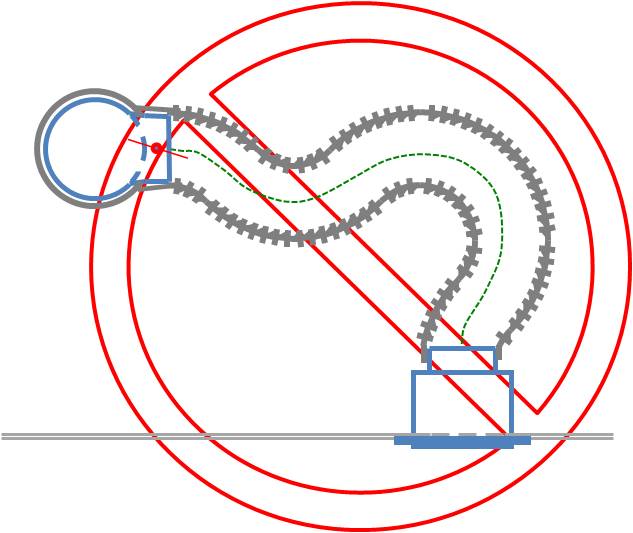
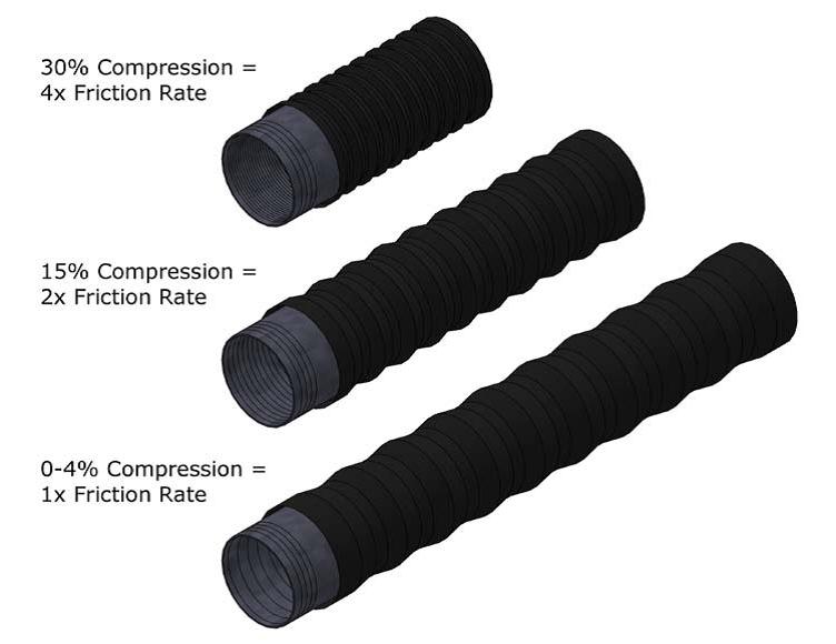
Figure 5. Cut the duct to the length needed. Do not loop excess duct. - Pull the duct until fully extended before mechanically attaching it to the duct boots to reduce friction. Compressing the duct or using excessive length will noticeably increase friction losses.
Keep the duct’s centerline relatively straight, with no significant sag or snaking. Limit sag to 2.5 inches per 5 feet of span, or less, as shown in Figure 6.
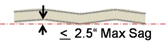
Figure 6. There should be less than 2.5 inches per each five foot of duct length. Use balancing dampers at trunk lines, if needed, to control airflow.

Figure 7. If airflow must be limited to a supply register, use balancing dampers at the trunk line rather than looping duct to control airflow.
Ensuring Success
Consider duct layout in the initial framing design stage to plan for short, straight duct runs wherever possible. Inspect before drywall is installed to ensure that ductwork is installed in the straightest line possible from the air handler to the end of the trunk line and from the trunk line to the supply air registers, that the flexible duct is pulled taut and properly supported, and that the radius of all directional changes is no less than the diameter of the flexible duct. Use a duct blaster test to confirm proper air flow at each duct supply outlet.
Region
No climate specific information applies.
Training
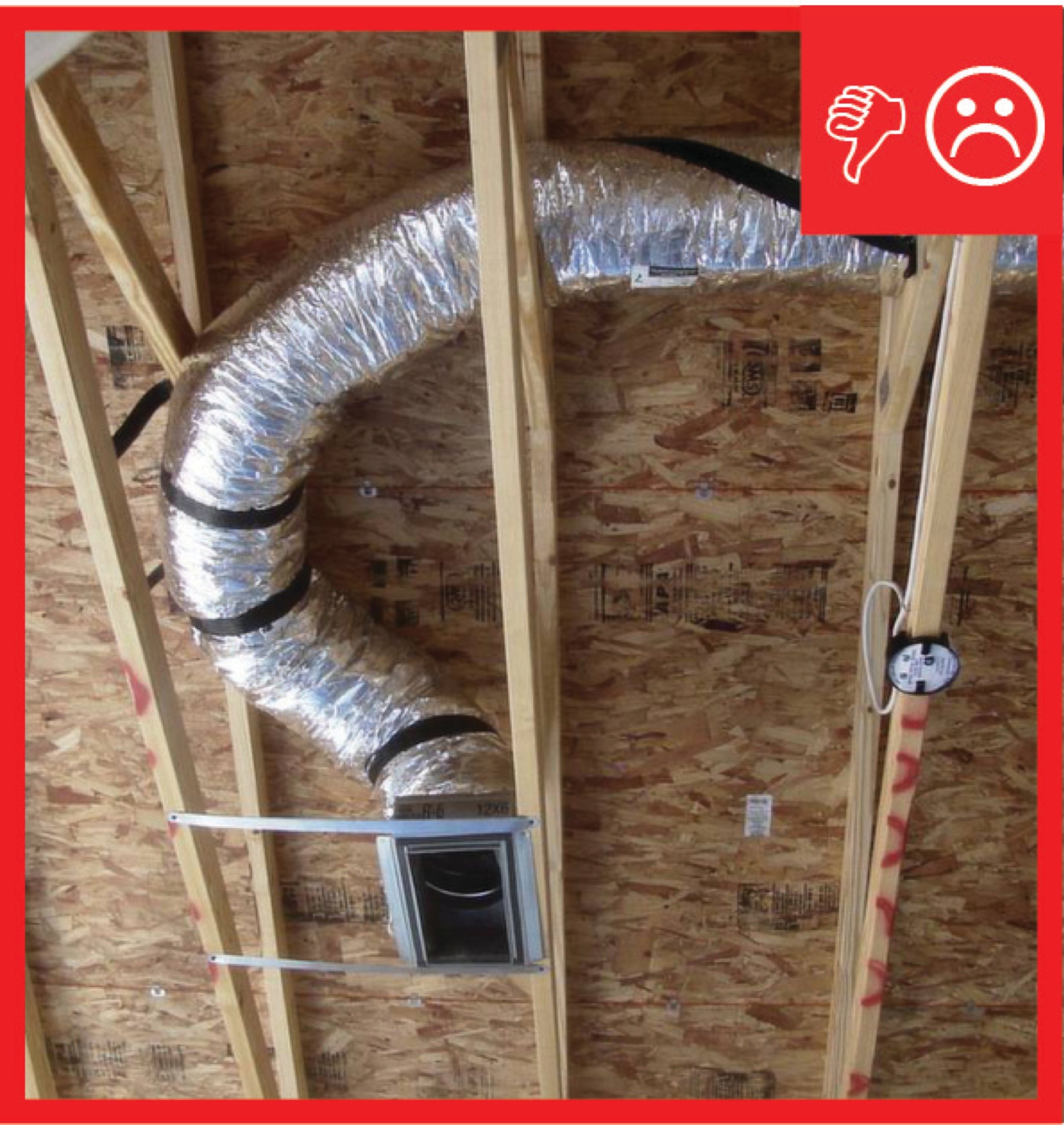
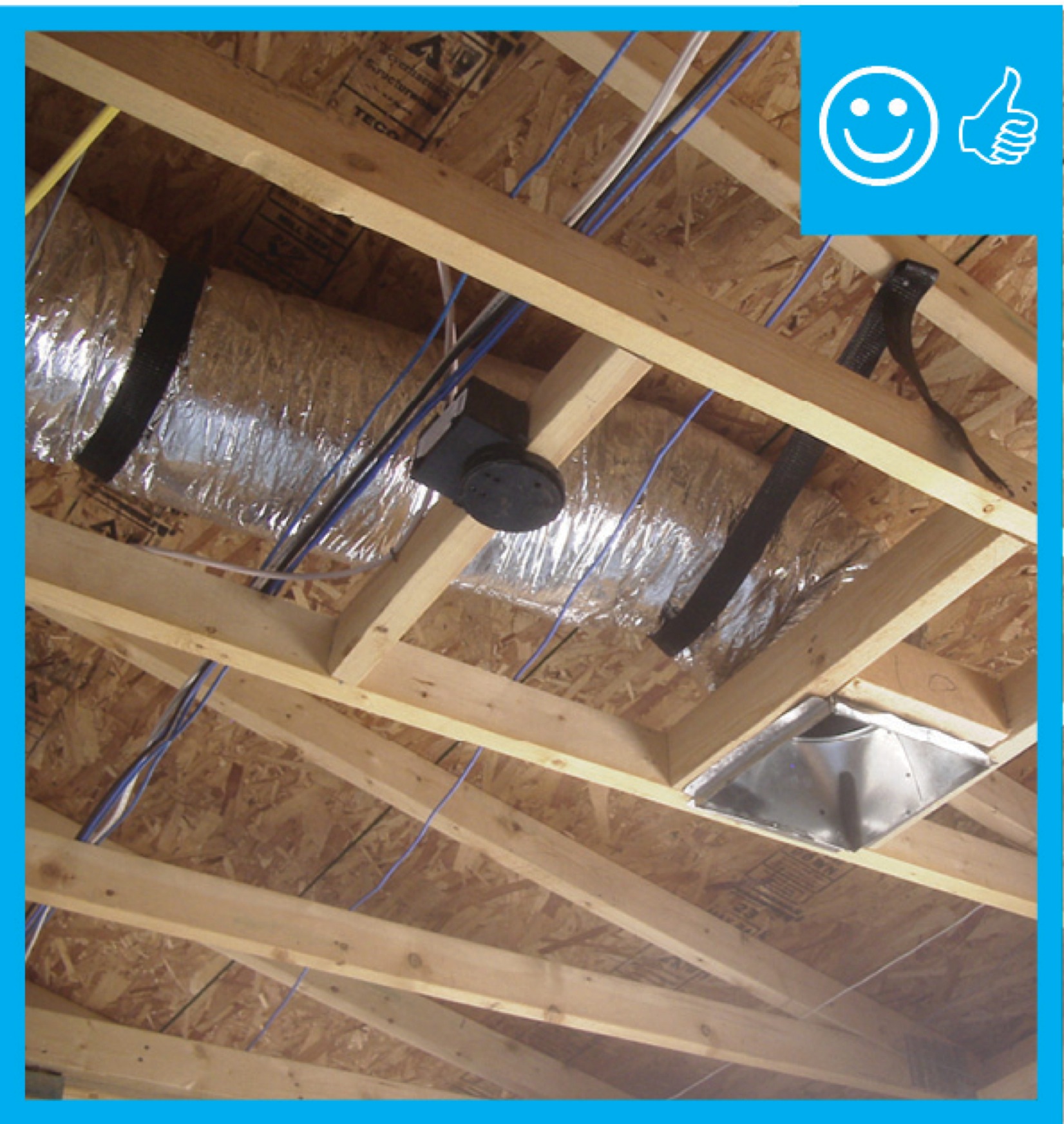
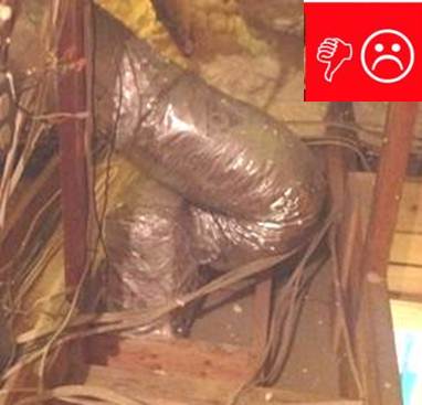
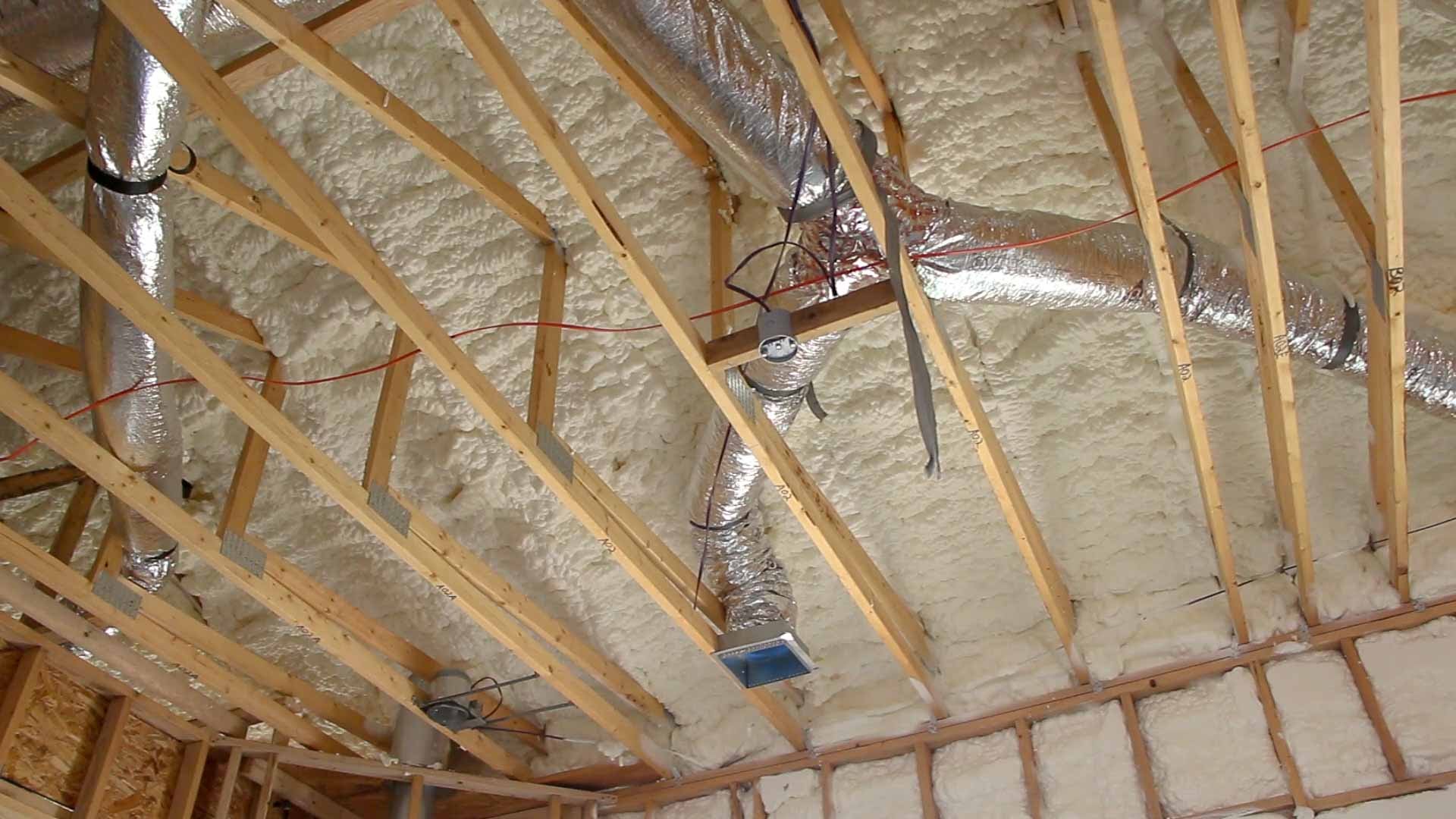
Right and Wrong Images
Source
Source
Videos

Retrofit
SCOPE
Additions: Flex ducts may be added to the existing HVAC distribution system to deliver conditioning to new spaces resulting from a remodel or addition.
Existing Buildings: In an existing building with an under-performing HVAC system an assessment may reveal the existence of excessive coils or loops which prevent conditioned air from being delivered to the target spaces, cause excessive noise, and burden the fan due to increased static pressure.
If the ducts are located in the attic, review the guide Pre-Retrofit Site Assessment of Ceilings, Attics, and Roofs.
If the ducts are located in the basement or crawlspace, review the guide Pre-Retrofit Site Assessment of Crawlspaces and Basements.
For more information about ducts see the U.S. Department of Energy’s Standard Work Specifications.
DESCRIPTION
For the installation of flex duct in retrofit and existing building situations, follow all best practices and precautions described for new construction.
Additions: See “Existing HVAC System Upgrade or Expansion” for a discussion on when and how to add ductwork to an existing distribution system to provide conditioning for additional floor area. Coordinate the duct layout for a new room with the design of the structure and other systems to ensure there is space for proper routing of the ducts. As with new construction, use ACCA Manual D and provide a schematic of the layout to the homeowner for future reference. Existing Buildings: See “Pre-Retrofit Assessment of Existing HVAC Systems” for a discussion of how to determine if a flawed duct design may be contributing to poor HVAC system performance. Follow ACCA Manual D.
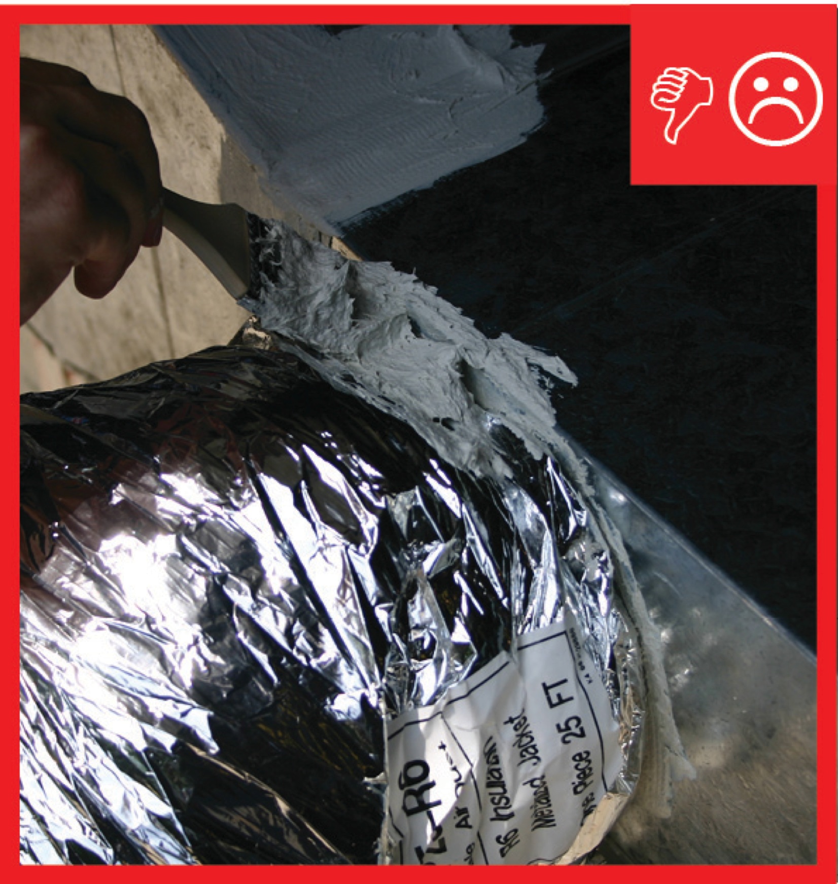
If flex duct is not cut to the proper length at the time of installation, the potential for noise and pressure drop is greatly increased. Wherever possible when excess duct is encountered, detach the end from the duct boot, pull and trim off the excess then reattach with mechanical fasteners and seal the duct and insulation using mastic and/or metal tape. Occasionally an installer will leave a long loop assuming this aids in balancing. Per ENERGY STAR Version 3.0: “balancing dampers or proper duct sizing shall be used instead of looped or coiled ductwork to limit flow to diffusers.” (National HVAC Commissioning Checklist, footnote 5) . The initial duct installer may also have left several extra feet of flex duct in place for noise reduction when the register is very close to the takeoff from the trunk or to the fan itself. Trim if possible and only use the minimum length necessary to avoid “line of sight” from register to takeoff. In such a case, the remaining extra length should be installed with a gradual curve to ensure that airflow is not restricted.
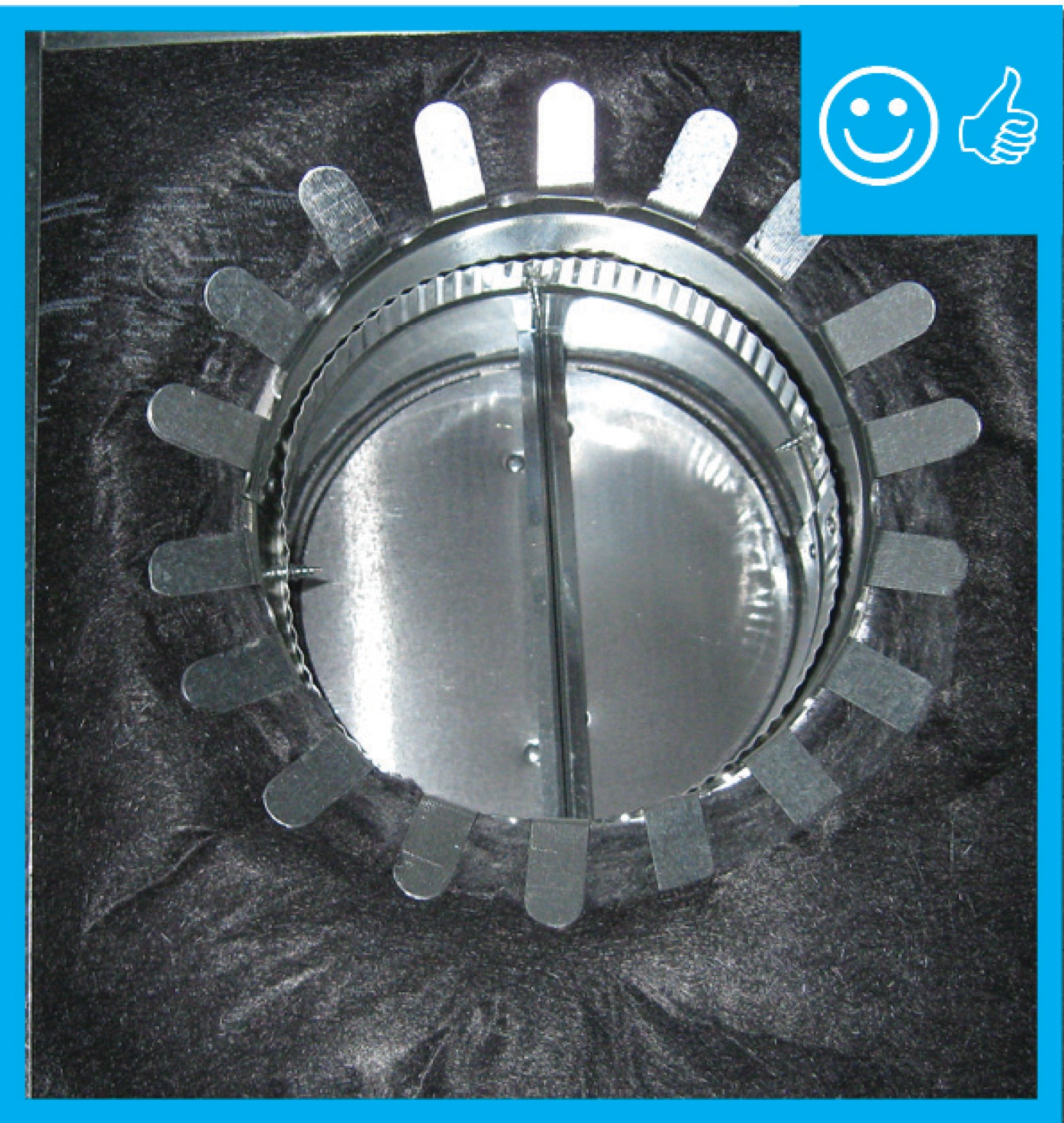
Whenever duct transitions must be made, ensure that the duct itself, the insulation, and the jacket are air-sealed: See Sealed and Insulated Flex Ducts for detailed guidance.
SUCCESS
When re-routing ductwork, access directly from the basement, crawlspace, or attic if possible. If the ducts are behind finish materials like drywall it is tempting to make the smallest possible openings in existing ceilings and walls in an effort to reduce disruption. However, flex duct is tender by nature and is likely to collapse if forced into place from a distance. It will be impossible to fully examine the entire duct layout if openings are too small. Instead, cut openings in drywall large enough to the fit head and shoulders of the installer so that the flex duct can be manipulated into the best possible orientation. Use ample hangers to hold the duct in place and be sure to open the ceiling directly below any connections that must be adjusted so that collars or strapping can be examined from all directions to ensure a tight seal.
CLIMATE
If you are already working on an existing system, that is the time to remedy any duct insulation issues. Starting with the 2009 International Energy Conservation Code (IECC), supply ducts located in unconditioned space must be insulated to at least R-8 and return ducts must be insulated to R-6. Although an existing system is generally not required to be brought up to code (double check this with the local AHJ), you should take this opportunity to add insulation to deficient systems, especially if you see evidence that condensation has been occurring.
Uninsulated (or under-insulated) ducts in unconditioned spaces result in a large portion of your heating and cooling dollars being wasted. In humid climates, it also compromises building materials such as lumber, drywall, fasteners, and fixtures because warm, humid air will condense on a cold surface (like a duct delivering chilled air) results in the formation of liquid water that can cause rust, encourage mold, and seep through ceiling drywall to create unsightly staining. Repair and replacement of these items can easily cost more than the preventative duct insulation.
See Sealed and Insulated Flex Ducts for guidance.
COMPLIANCE
See Compliance tab.
More Info
References and Resources
*For non-dated media, such as websites, the date listed is the date accessed.
Contributors to this Guide
The following authors and organizations contributed to the content in this Guide.
Sales
Proper Duct Installation = Professionally-Installed Comfort Delivery Ducts
Technical Description
Conditioned air is often lost in transition from comfort equipment to living spaces because of poorly designed duct layouts and poor installation practices, which cause homeowners to pay for conditioned air that never reaches the living spaces of their home. Poor duct layouts with overly long duct runs, numerous branches, and sharp bends, and poor installation with sagging, twisted, or crushed ducts, can severely limit air flow, reducing system performance and increasing energy costs. Professionally installed comfort delivery systems should be installed with compact duct layouts featuring short, straight duct runs with properly supported ducts, in accordance with industry standards. The ducts should be properly insulated, completely air sealed, and free from kinks and sharp bends that restrict air flow.
Questions? Comments? Contact our webmaster.