

Scope
Duct Distribution Quality Installation
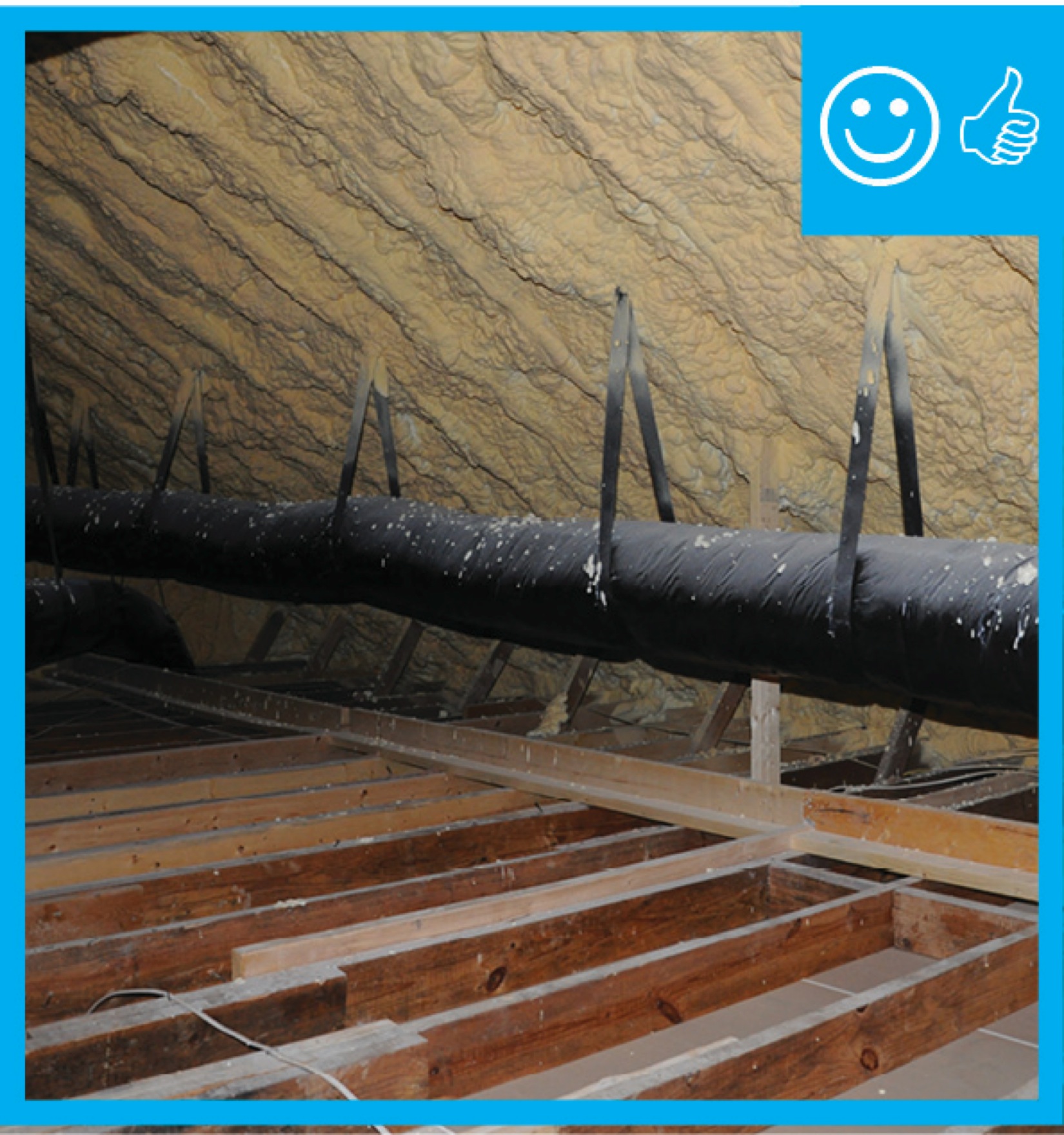
If ducts are to be installed in a vented, uninsulated attic or crawl space, hang the ducts with supporting straps or saddles of sufficient width and frequency to adequately support the ducts so that the ducts do not sag and are not pinched or compressed in a manner that would cause damage to the ducts, the duct insulation, or the duct air barrier covering.
Follow the Air Conditioning Contractors of America (ACCA) Manual D recommendations for flex duct installation. ACCA recommends that ducts should be installed with no significant sag or snaking and that installation methods should follow the guidance provided in the ADC (Air Diffusion Council) Flexible Duct Performance and Installation Standard, 5th edition, 2010, Sections 4 and 5. The ADC Standards (5th edition, Section 4.6) make the following requirements regarding support of flexible duct.
- The ducting should be supported at the manufacturer’s recommended intervals, but the supports should be no greater than 4 feet apart and there should be no more than ½ inch sag per foot between the supports. A connection to rigid duct or equipment is considered a support joint.
- Long horizontal duct runs with sharp bends should have additional supports before and after the bend.
- Supports should be at least 1.5 inches wide.
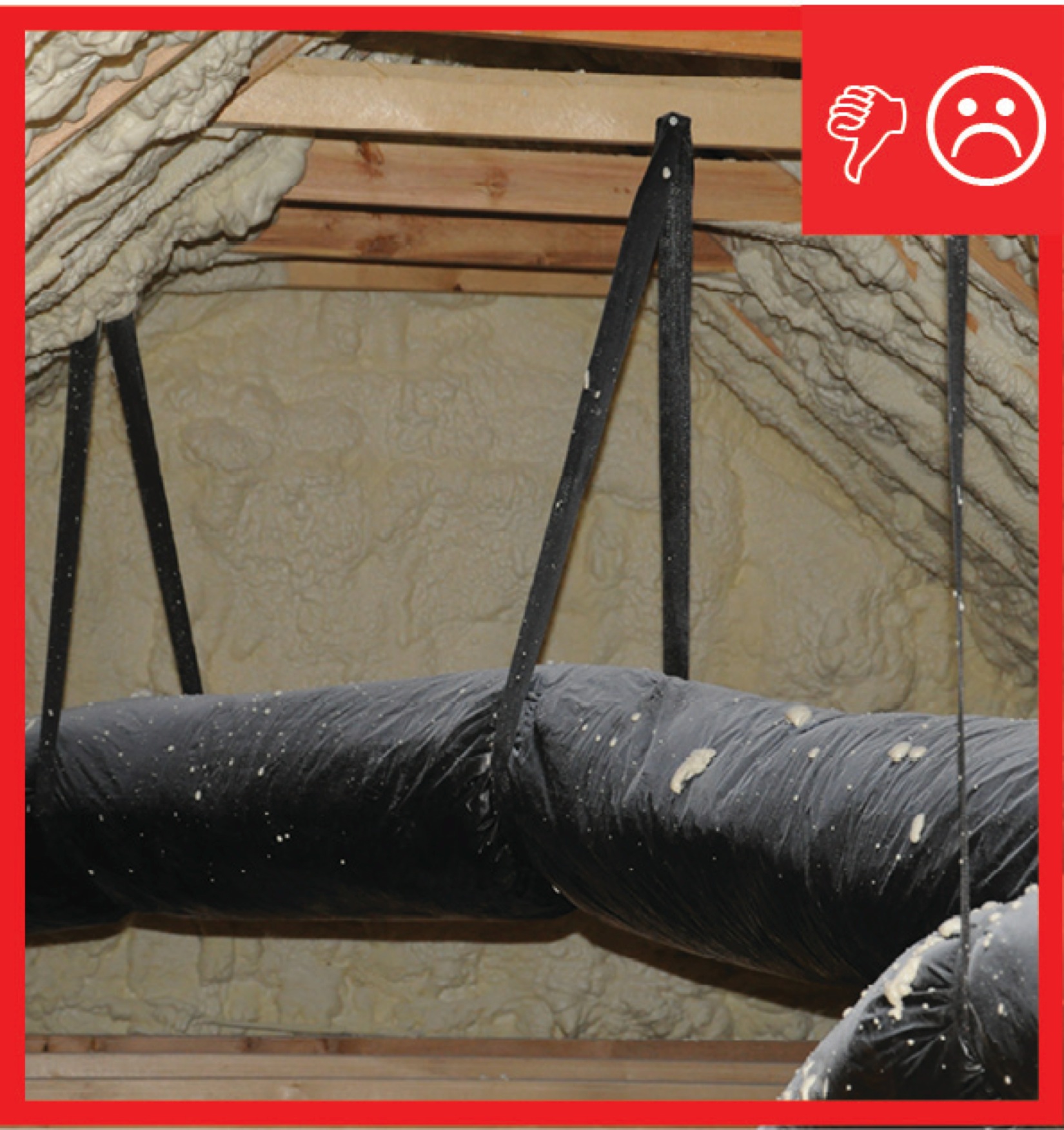
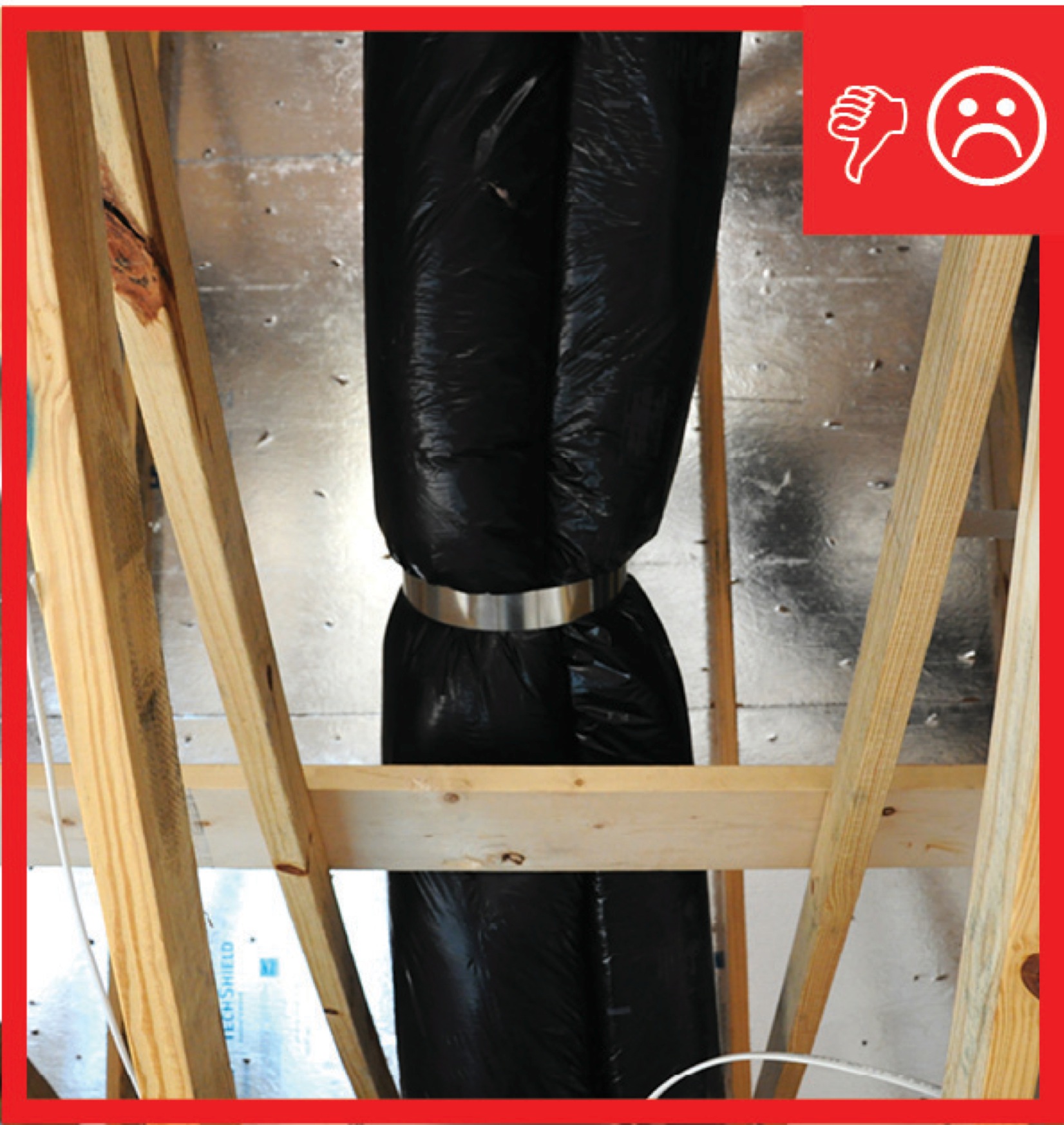
- Straps should not compress the inner core or constrict air flow. The supports should not excessively compress the vapor barrier and insulation material because compressing the insulation could lead to condensation at that point.
- Factory-installed support systems that are part of the flex duct can be used if manufacturer’s procedures are followed.
- Flexible ducts may rest on ceiling joists or truss supports, if the manufacturer’s support spacing guidance is followed.
- A support should be installed between a metal connection and a bend and the duct should be allowed to extend straight for at least one duct diameter before making the bend.
- Vertically installed ducts shall be supported every 6 feet at a minimum.
See the Compliance Tab for links to related codes and standards and voluntary federal energy-efficiency program requirements.
Description
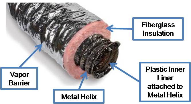
Flexible duct, known as flex duct, is very convenient ducting for attaching supply air outlets to rigid trunk ductwork, and, in many cases, flex duct comprises the entire duct system. Flex duct made for HVAC applications is typically constructed of a plastic inner liner attached to a metal wire helix (or coil) to make round flex duct. The duct comes with a layer of fiberglass blanket insulation already attached around the duct. The insulation is covered and protected by a polyethylene or foil vapor barrier. Flex duct is typically available in insulation values of R-4, R-6, and R-8. For residential HVAC systems, insulated flex duct typically comes in diameters of 4 inches through 10 inches; above 10 inches, it comes in even sizes of 12, 14, 16, etc., up to 22 inches measured at the radius of the metal helix.
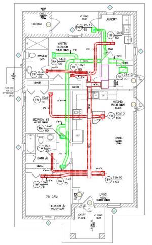
Ideally, ducts should be located inside conditioned space, i.e., within the thermal envelope of the home. This could be in a dropped ceiling duct chase; in an insulated and air sealed attic, basement, or crawlspace; or between the floors of a two-story home. However, ducts are often installed in uninsulated, unsealed crawlspaces or attics that are outside the thermal envelope or conditioned space of the home. In these locations, the ducts must be thoroughly air sealed and insulated and properly installed and supported to avoid air flow losses, energy losses, and moisture problems.
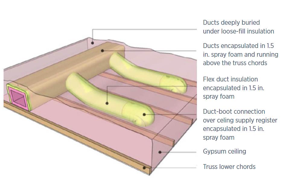
In attics in dry climates, ducts can be laid on the ceiling joists or ceiling deck and covered with blown insulation (Figure 2). In humid or mixed-humid climates, ducts cannot be laid on any flat surface (such as the ceiling deck or ceiling joists whose cavities are filled with insulation) because of concerns about the formation of condensation on the outside of the ducts under the right dew point conditions. The only exception to this is if the ducts are first sealed, insulated, and completely encapsulated in at least 1.5 inches of closed-cell spray foam (Figure 3 Shapiro et al. 2013). Building America recommends, and DOE Zero Energy Ready Home requires, that in all climates, if ducts are to be “buried,” they must first be insulated with R-8 duct insulation then encapsulated with at least 1.5 inches of closed-cell spray foam insulation, then covered with at least 2 inches of blown insulation.
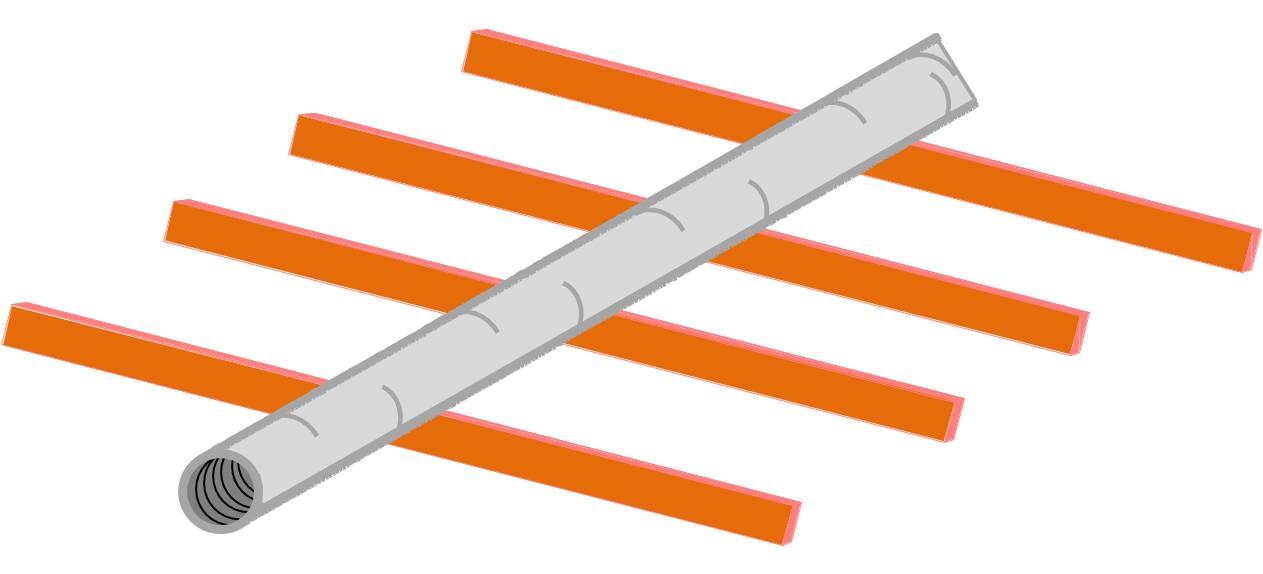
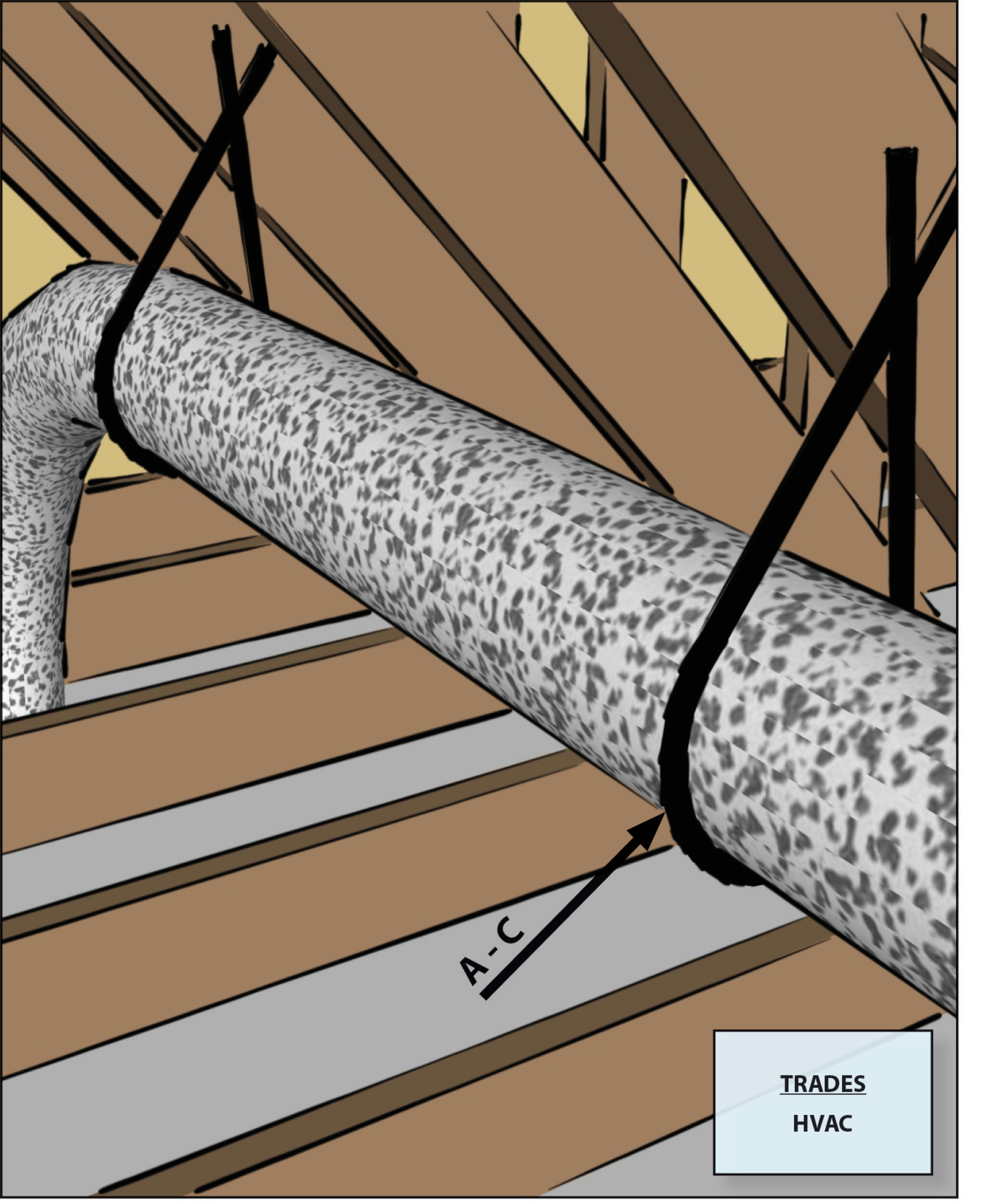
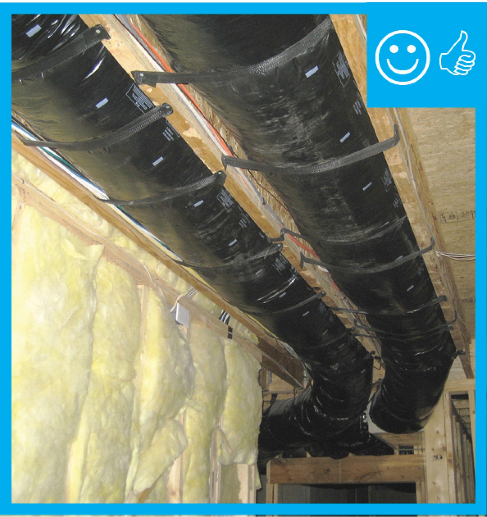
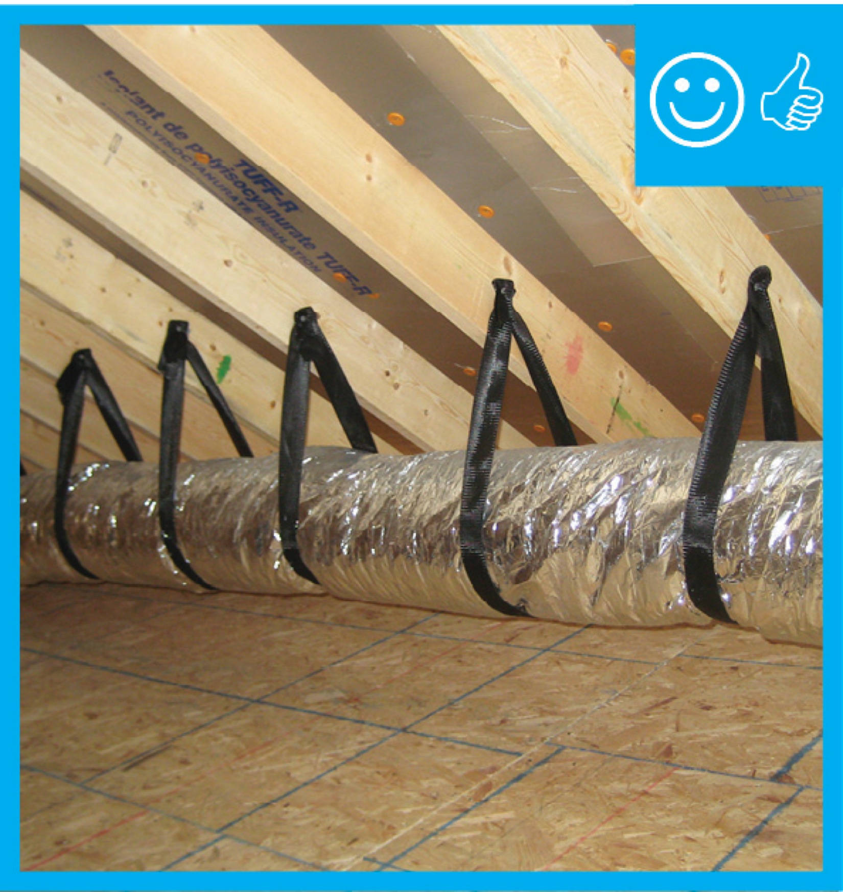
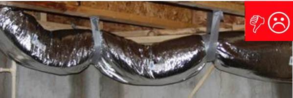
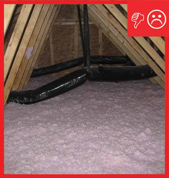
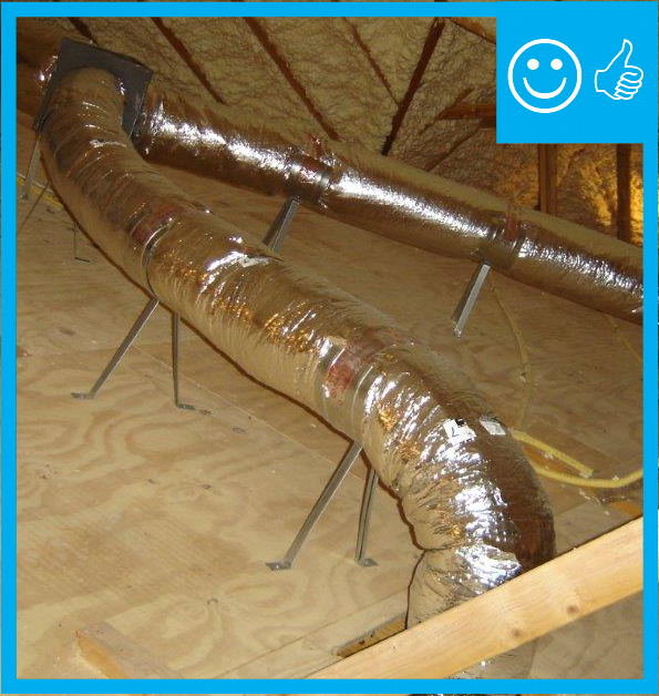
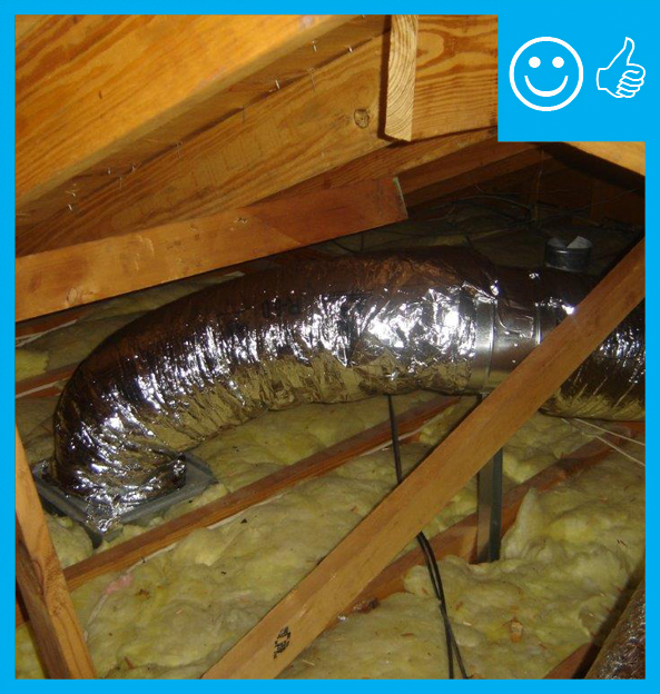
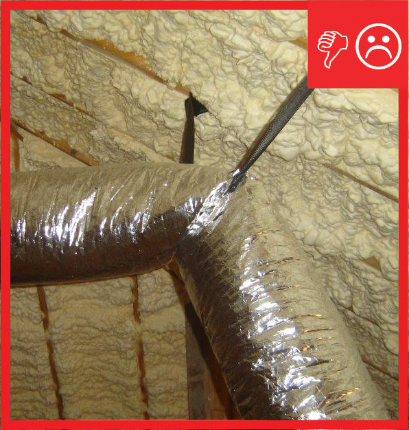
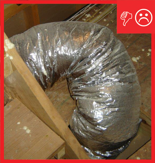
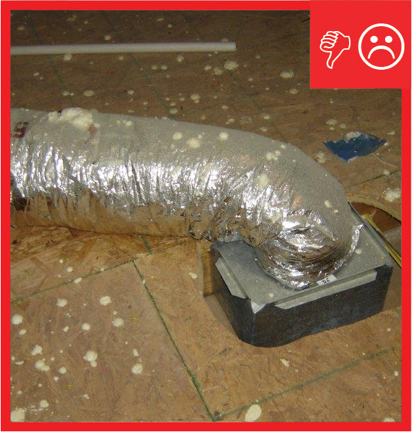
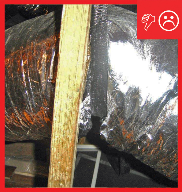
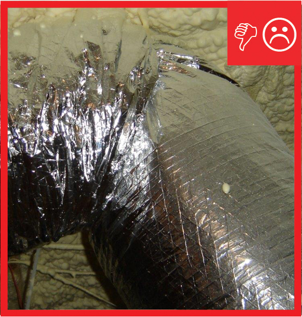
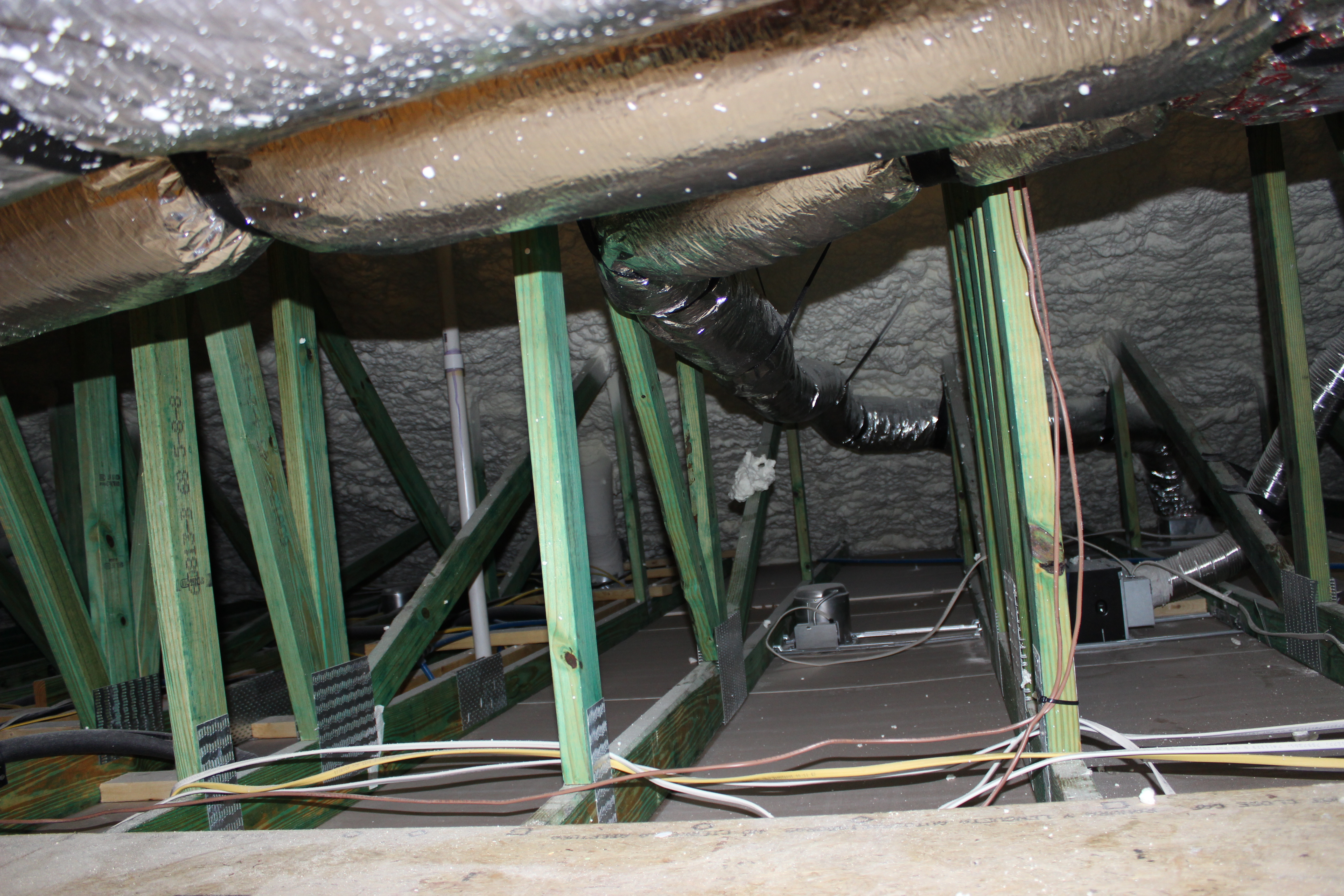
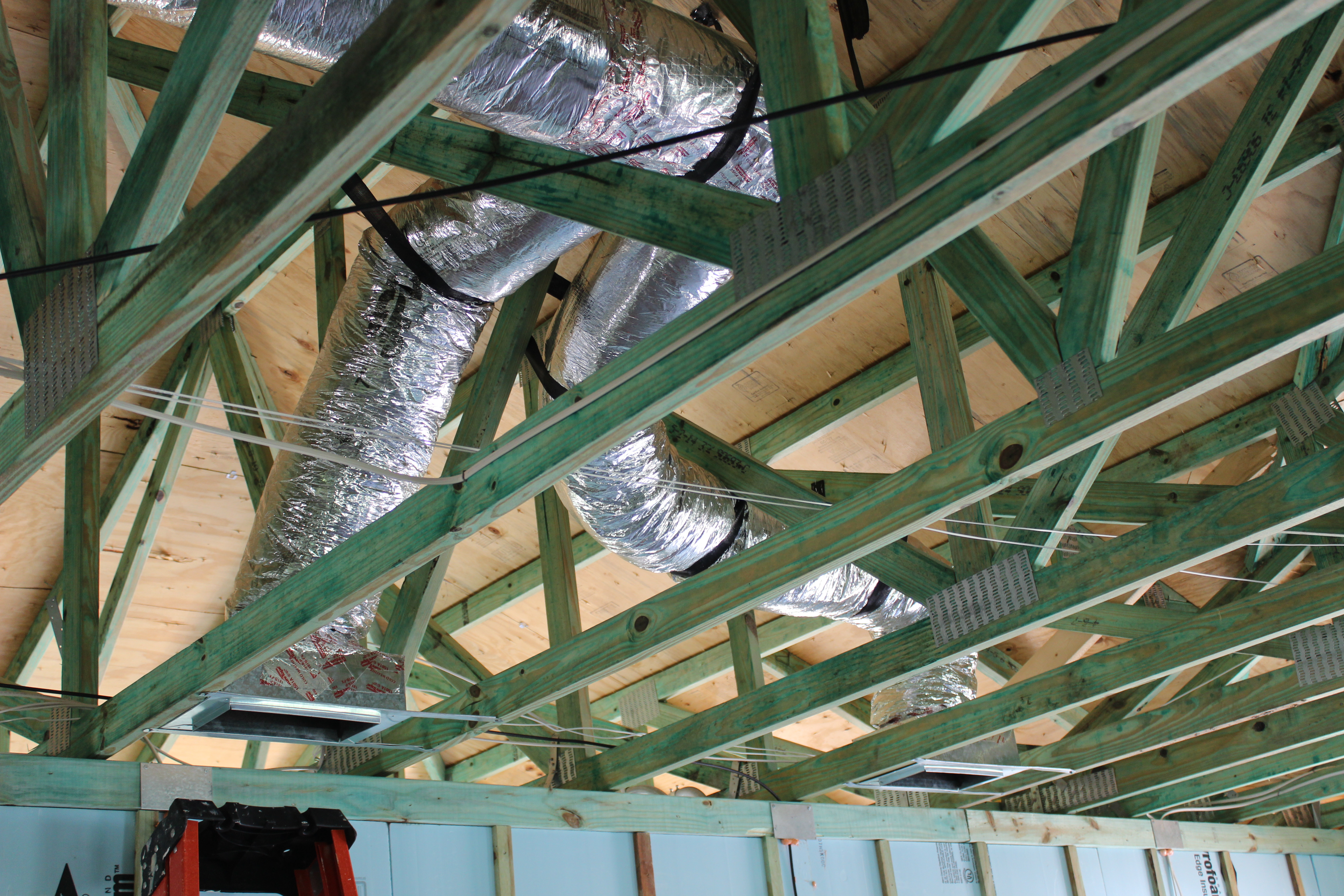
If the buried and encapsulated duct technique cannot be accommodated, then the ducts are typically hung from the attic ceiling with strapping or supported in saddles anchored to the attic framing. The flex duct must be adequately supported to ensure the duct is not crimped and to maintain both air flow through the duct and the integrity of the duct coil and insulation material. When the flex duct is improperly supported, for example by spacing the support straps or saddles too far, the ducts can sag, restricting air flow. When the support straps are too narrow or too tight, the metal helix or plastic inner liner of the flex duct can be crushed or damaged, restricting air flow and compromising the insulation. If the insulation is overly compressed, cold spots can occur on the exterior of the duct where condensation can form in hot, humid attics. Crushed ducts can eventually fail causing air leakage and large energy losses. Hanger straps or saddles need to be wide enough to prevent the straps from compressing the insulation and cutting into the inner liner. Straps or saddles must be adequately spaced to prevent sagging of the ducts.
In hot-humid climates, if ducts are to be installed in an uninsulated, vented attic, hang the ducts in the hottest part of the attic to maintain the surface temperature of the ducts above the dew point and minimize contact of the ducts with other objects in the attic (Bailey and Swanson 2014).
Manual D Residential Duct Systems (ACCA 2009) sets standards for flex duct design and installation. See Appendix 17 for a detailed discussion of duct installation. The Flexible Duct Performance Standards (Fifth Edition) by the Air Diffusion Council (ADC 2010) provides guidance to designers, architects, engineers, contractors, and installers.
For more on flex duct installation, see No Kinks or Sharp Bends in Flex Duct Installation, Sufficient Cavity Space for Flex Ducts, No Excessive Coiled or Loped Flex Ducts and Sealed and Insulated Flex Ducts.
How to Properly Support Flex Duct that is Hung in an Attic or Crawlspace
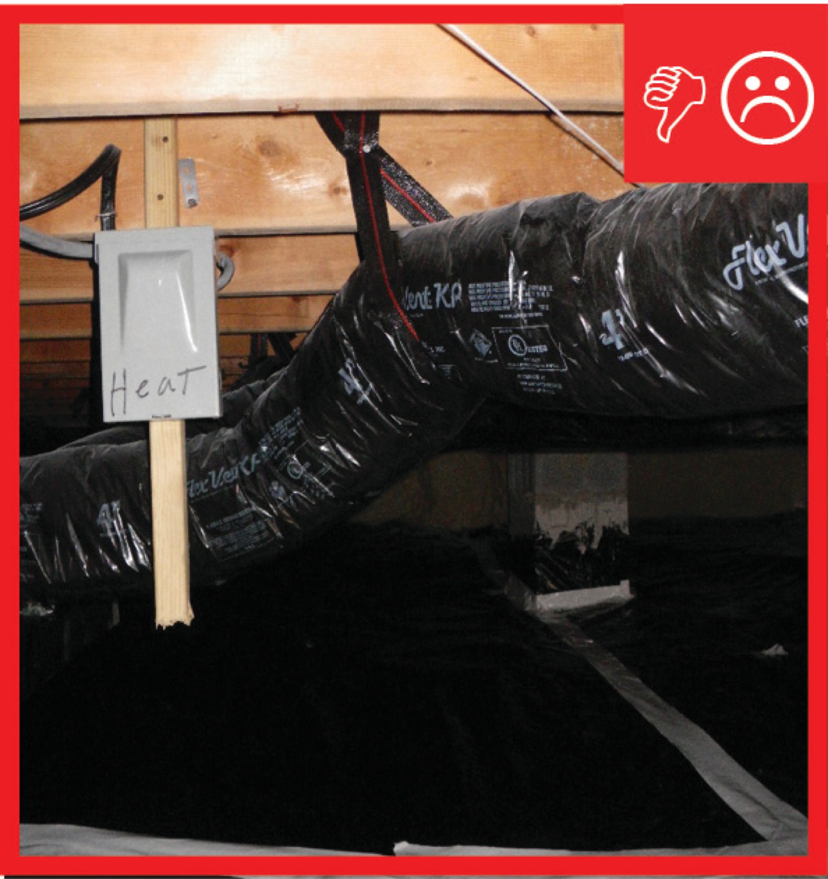
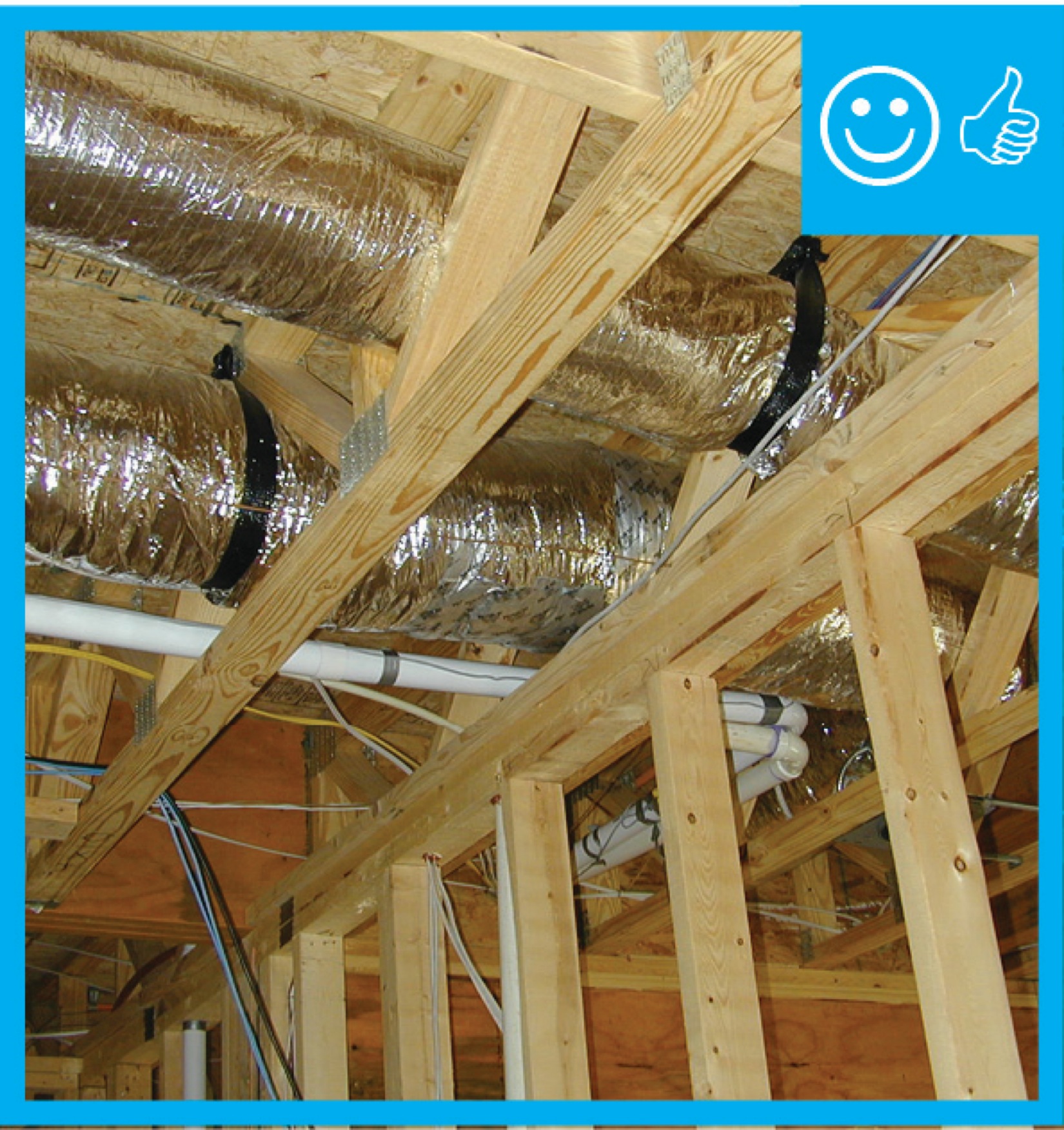
Support flex duct using straps or saddle supports or as specified by the manufacturer. Hanger straps in contact with flex duct should be at least 1.5 inches wide, preferably wider, (ADC 2010) and should be sufficiently loose to prevent restriction of the internal diameter of the duct when the weight of the supported section rests on the hanger or saddle material. Factory-installed suspension systems integral to the flexible duct are an acceptable alternative hanging method when the manufacturer’s recommended procedures are followed. Ducts can also be supported by a saddle-shaped support held up by a pole that is attached to attic framing. The supporting width of the saddle must exceed 5.5 inches along the length of the duct (ICC-ES 2007).
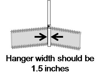
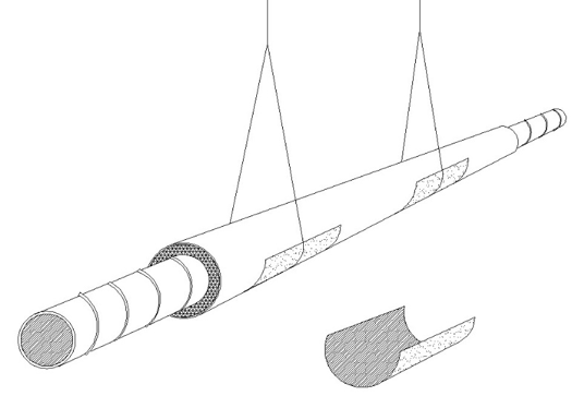
Figure 4. Hanger straps should be at least 1.5 inches wide. (Source: Calcs Plus.) Space supports at 4-foot intervals or closer to ensure that the flexible duct does not sag more than 1/2 inch per lineal foot between the supports.
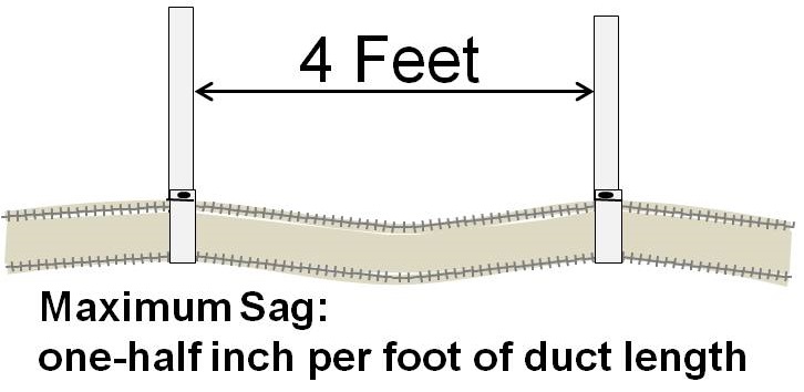
Figure 5. Supports should be installed at least every once 4 feet. The maximum allowable sag in flexible duct is one-half inch per foot. (Source: Calcs Plus.) - Place supports at each connection between flex duct and rigid metal duct. For example, in Figure 6 a hanger is placed at the trunk line where a flex connection is made.
- Ensure that strapping, framing, or other supports are in place to support all air devices (such as diffuser boxes, register boxes, or grille boxes) and all duct peripherals (such as junction boxes, wyes, plenums, etc.).
Support the flex duct between a metal connection and a bend by allowing the duct to extend straight for a distance equal to or greater than the radius of the flex duct being installed before making a bend. The support will hold the duct straight for an adequate distance from the connection to avoid possible damage to the flex duct by the metal edge of the collar.
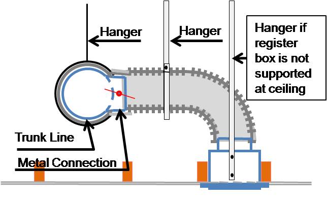
Figure 6. Ensure that hanger straps or other supports are in place to support the flex duct between a metal connection and a bend, to support trunk lines at a branch duct connection, and to support supply registers and other duct connections. (Source: Calcs Plus.) Support duct before and after sharp bends (see Figure 7).

Figure 7. Install duct supports before and after any sharp bends in ducts. (Source: Calcs Plus.) - Support any vertically installed sections of flex duct with support straps installed at no more than 6 feet apart.
Ensuring Success
Plan for duct layout in the initial plans so that framing obstacles can be minimized. Install ducts within the thermal boundary of the home if possible. If installed in an uninsulated attic in dry climates, ducts can be laid on the ceiling deck and buried in blown insulation. In humid climates, encase the ducts in closed-cell spray foam. If ducts are hung, inspect that ducts are supported at least every 4 feet with strapping that is at least 1.5 inches wide (wider is better) and with no more than ½ inch of sag per lineal foot between supports.
Region
For best performance, install ducts within the home’s thermal envelope. If installed in an uninsulated attic in dry climates, ducts may be laid on the ceiling deck. In the humid, mixed-humid, and marine climates, the ducts must be encapsulated in closed-cell spray foam if installed on the ceiling deck. Or, ducts can be hung from the attic ceiling with strapping or supported with saddle supports. In humid climates, ducts in vented attics should be hung or supported in the hottest part of the attic and contact of the ducts with other objects in the attic should be avoided to reduce the possibility of condensation forming on the ducts.
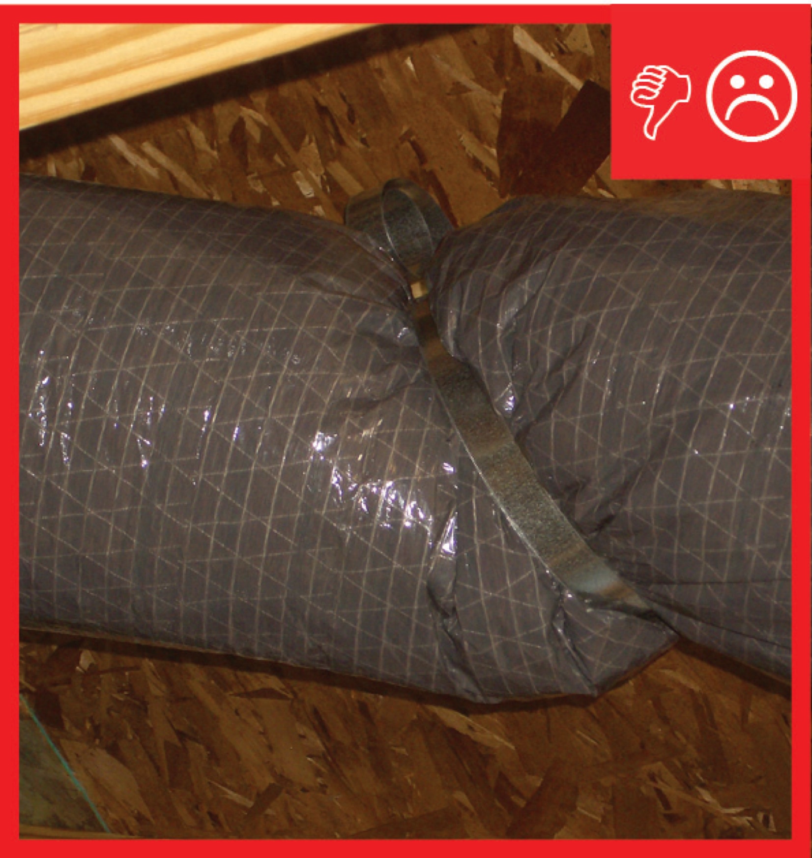
The map in Figure 1 shows the climate zones for states that have adopted energy codes equivalent to the International Energy Conservation Code (IECC) 2009, 12, 15, and 18. The map in Figure 2 shows the climate zones for states that have adopted energy codes equivalent to the IECC 2021. Climate zone-specific requirements specified in the IECC are shown in the Compliance Tab of this guide.
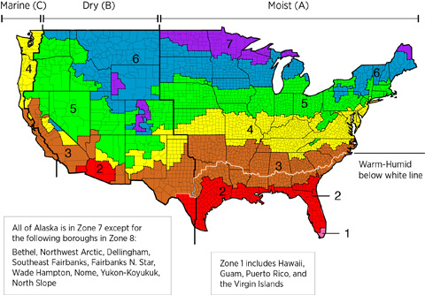
Figure 1. Climate Zone Map from IECC 2009, 12, 15, and 18. (Source: 2012 IECC).

Training
Right and Wrong Images
Source

Source
Source

Source
Source
Source
Source
Source
Source
Source
Source
Source
Source
Videos
Compliance
Retrofit
SCOPE
Additions: If new flex duct is added to an existing home, either as part of an addition or an equipment upgrade, ensure that the flex duct is installed in runs that are as short, straight, and direct as possible, and properly support the duct through the use of hangers or stands as noted in the Description tab.
Existing Buildings: In an existing building with flex duct and an under-performing HVAC system, inspect for sagging or pinching of the flex duct due to lack of adequate support. Symptoms may include minimal air flow to a terminal, excessive noise, or fan burnout due to increased static pressure.
If the ducts are located in the attic, review the guide Pre-Retrofit Site Assessment of Attics, Ceilings, and Roofs.
If the ducts are located in the basement or crawlspace, review the guide Pre-Retrofit Site Assessment of Crawlspaces and Basements.
For more information see the U.S. Department of Energy’s Standard Work Specifications regarding duct support.
DESCRIPTION
For the installation of flex duct in retrofit and existing building situations, follow all best practices and precautions described for new construction. A typical cause of excessive static pressure occurs when flex duct is not properly supported, which allows sagging and pinching of ducts.
Additions: See Existing HVAC System Upgrade or Expansion for a discussion of when and how to add spaces to an existing distribution system. Coordinate the duct layout for a new space with the design of the structure and other systems to ensure there is space for proper routing. As with new construction, use ACCA Manual D and provide a schematic of the layout to the homeowner for future reference.
Existing Buildings: See Assessment of Existing HVAC Systems for a discussion of how to determine whether a flawed duct design may be contributing to poor HVAC system performance. If an inspection reveals that flex duct is sagging more than ½ inch per foot of duct length, it should be straightened to the extent possible.
- Support Ducts with Hanger Straps (generally in an attic)
- Add hangers (strapping at least 1.5-inches wide) where needed to ensure no hangers are more than 4 feet apart. If flex duct was left too long, shift duct lengths between support locations to stretch the duct as tight as possible, then cut off the excess and reconnect at a joint or duct boot. Carefully clamp the two cut ends over a non-flexible transition piece then fasten the inner liner to the collar with mechanical fasteners and seal with tape or mastic. Then cover with insulation and a plastic sheeting vapor barrier and seal the plastic to the trunk duct or boot collar with metal tape or mastic.
- Add hangers where needed to adequately support the duct at bends and at the transitions to devices and equipment.
- If hanger straps are narrower than 1.5 inches, make saddles from short lengths of stove pipe or sheet metal duct in diameters larger than the insulated diameter of the flex duct. Insert the saddles under the duct between the duct and the existing strap.
- Seal any tears or cuts in the plastic vapor barrier “jacket” covering the flex duct insulation to prevent humid summertime air from condensing on the cold ducting and causing condensation, which can lead to mold in the insulation.
- Support Ducts from Below
- If ducts are supported on upright braces or saddles, add braces if the existing braces are at intervals greater than 4 feet apart. Add additional braces as needed at transitions and bends.
- If ducts are resting on ceiling rafters and sagging into the bays between the rafters, additional support is needed, such as lumber blocking or plywood platform sections. If bays are not already full of insulation, pieces of batt insulation can be slid into place under the ducts between the rafters to support the duct and provide some additional sound blocking.

SUCCESS
When re-routing ductwork, access the ducts directly from the basement, crawlspace, or attic if possible. If the ducts are behind finish materials like drywall, it is tempting to make the smallest possible openings in existing ceilings and walls in an effort to reduce disruption. However, flex duct is likely to collapse if forced into place from a distance. It will be impossible to fully examine the entire duct layout if openings are too small. Instead, cut openings in drywall large enough to fit head and shoulders so that the flex duct can be manipulated into the best possible orientation. If flex ducts are disconnected, when reattaching them, fasten the inner liner to the collar with mechanical fasteners and seal with UL-181 tape or mastic, then cover with insulation and the plastic sheeting vapor barrier and seal the plastic to the trunk duct or boot collar with metal tape or mastic, as described in the guide Sealed and Insulated Flex Ducts.
CLIMATE
Starting with the 2009 International Energy Conservation Code (IECC), supply ducts located in unconditioned space must be insulated to at least R-8, and return ducts must be insulated to R-6.
Although an existing duct system is generally not required to be brought up to code when making repairs (double check this with the local code official), you can take this opportunity to check the ducts for duct leakage and seal all accessible seams and joints with mastic and/or UL-181 tape. You can also add duct insulation where it is lacking or deficient, especially if you see evidence that condensation has been occurring.
In humid climates, uninsulated or under-insulated ducts in unconditioned space can become a source of moisture damage. When warm, humid air comes in contact with the cold surface of a duct delivering chilled air, the water vapor can condense to liquid water that can cause rust in the ducts and mold in insulation, framing, and other building materials.
See Sealed and Insulated Flex Ducts for guidance.
More Info
Case Studies
References and Resources
*For non-dated media, such as websites, the date listed is the date accessed.
Contributors to this Guide
The following authors and organizations contributed to the content in this Guide.
Sales
Proper Duct Installation = Professionally-Installed Comfort Delivery Ducts
Technical Description
Conditioned air is often lost in transition from comfort equipment to living spaces because of poorly designed duct layouts and poor installation practices, which cause homeowners to pay for conditioned air that never reaches the living spaces of their home. Poor duct layouts with overly long duct runs, numerous branches, and sharp bends, and poor installation with sagging, twisted, or crushed ducts, can severely limit air flow, reducing system performance and increasing energy costs. Professionally installed comfort delivery systems should be installed with compact duct layouts featuring short, straight duct runs with properly supported ducts, in accordance with industry standards. The ducts should be properly insulated, completely air sealed, and free from kinks and sharp bends that restrict air flow.
Questions? Comments? Contact our webmaster.