

Scope
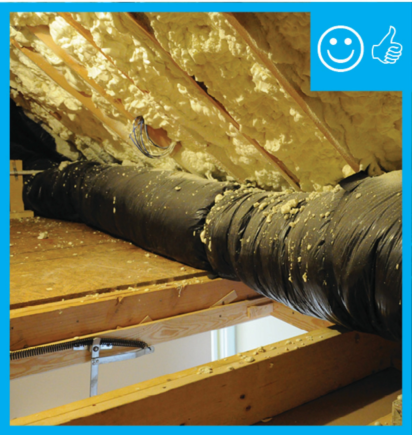
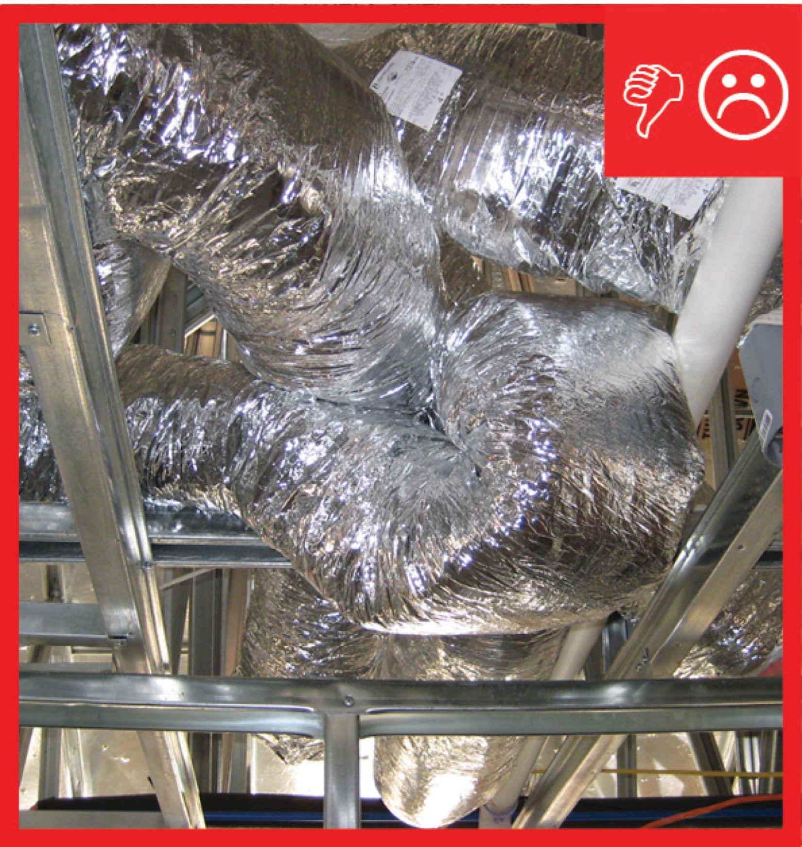
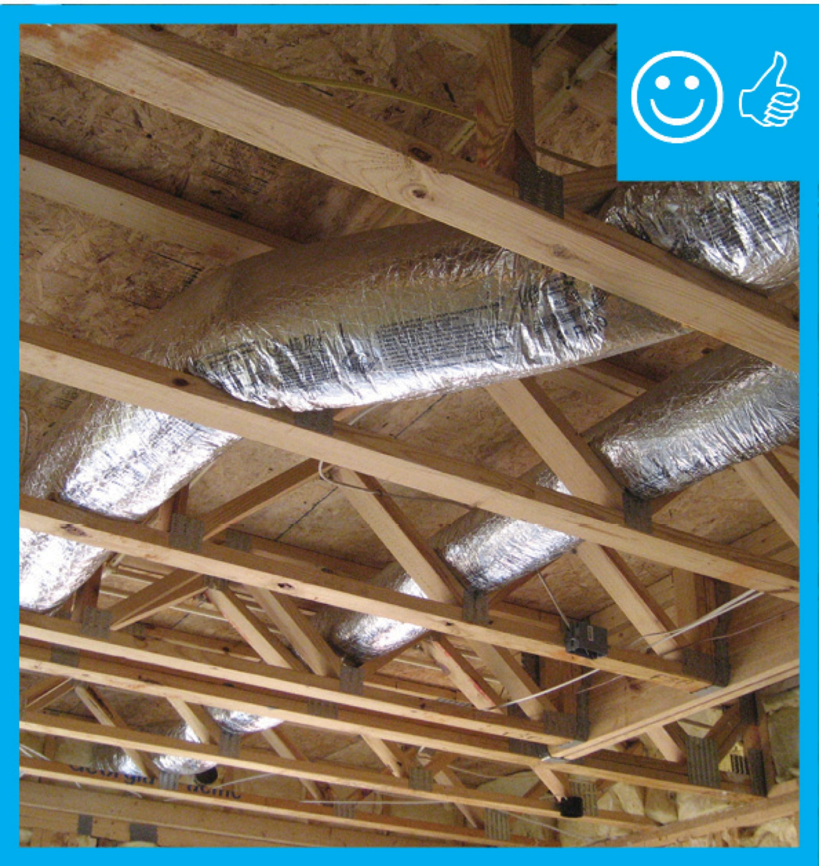
Install flex ducts without kinks or sharp bends.
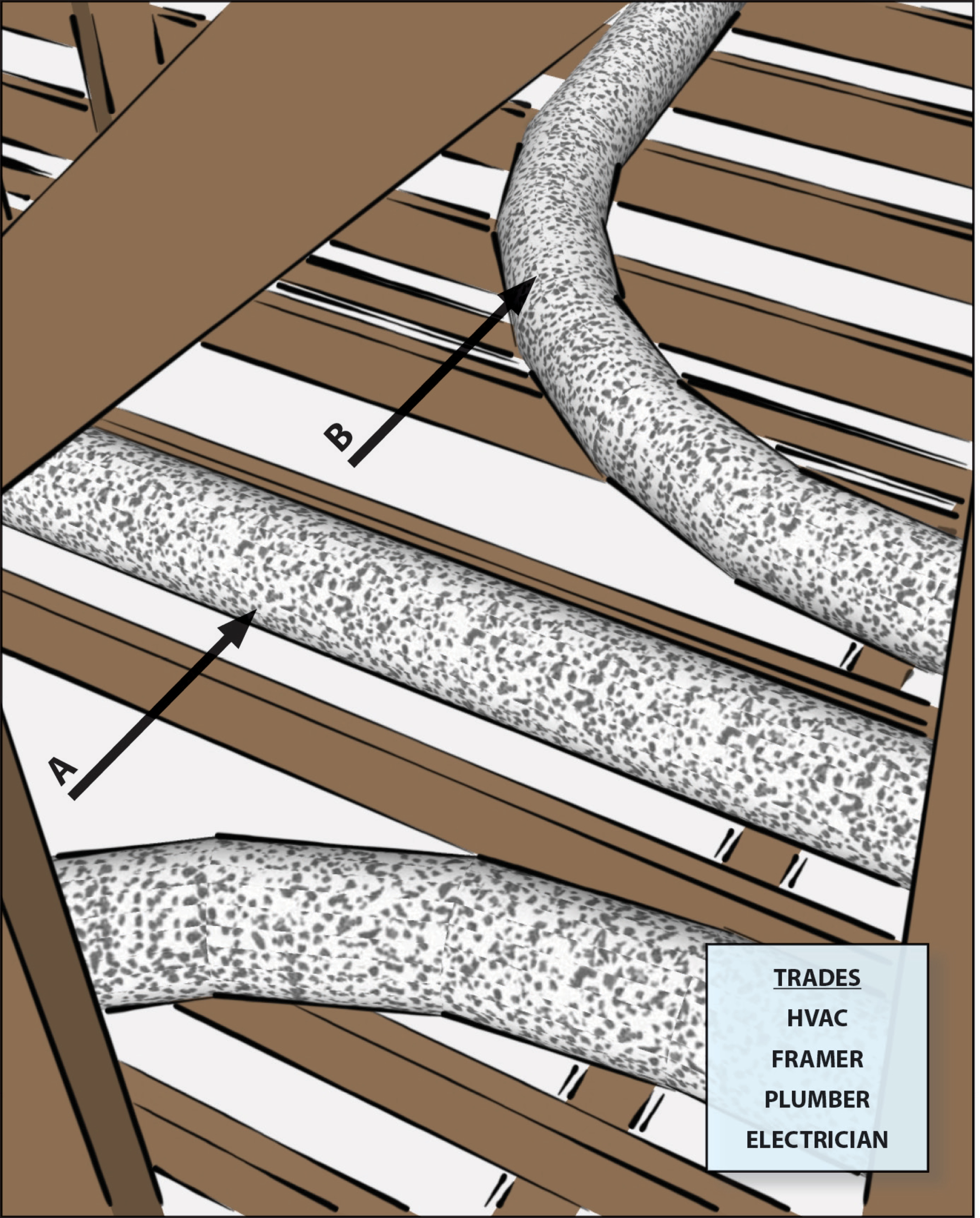
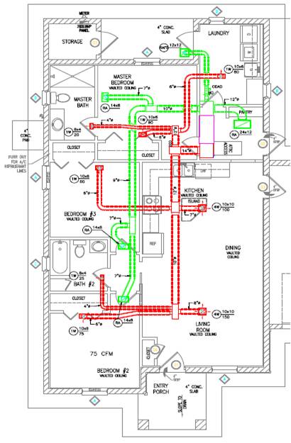
- Do not bend ducts across sharp corners such as framing members.
- Ensure that all bends are gradual rather than tight. The radius of each bend should be greater than the diameter of the flexible duct.
- Coordinate with the framer to plan for the shortest, most direct duct layout. Webbed trusses between floors allow for ducts to freely pass through the floor joists rather than being routed over them.
- Coordinate with the plumber and the electrician to avoid crushing ducts when other services are installed.
- Design ducts in compliance with Manual D.
- Use proper sized ducts or balancing dampers rather than loops in flex ducts to control air flow. For metal ducts, butterfly dampers may be used to control air flow.
- To prevent kinks at the duct and boot connections, consider using metal duct elbows instead of flex duct.
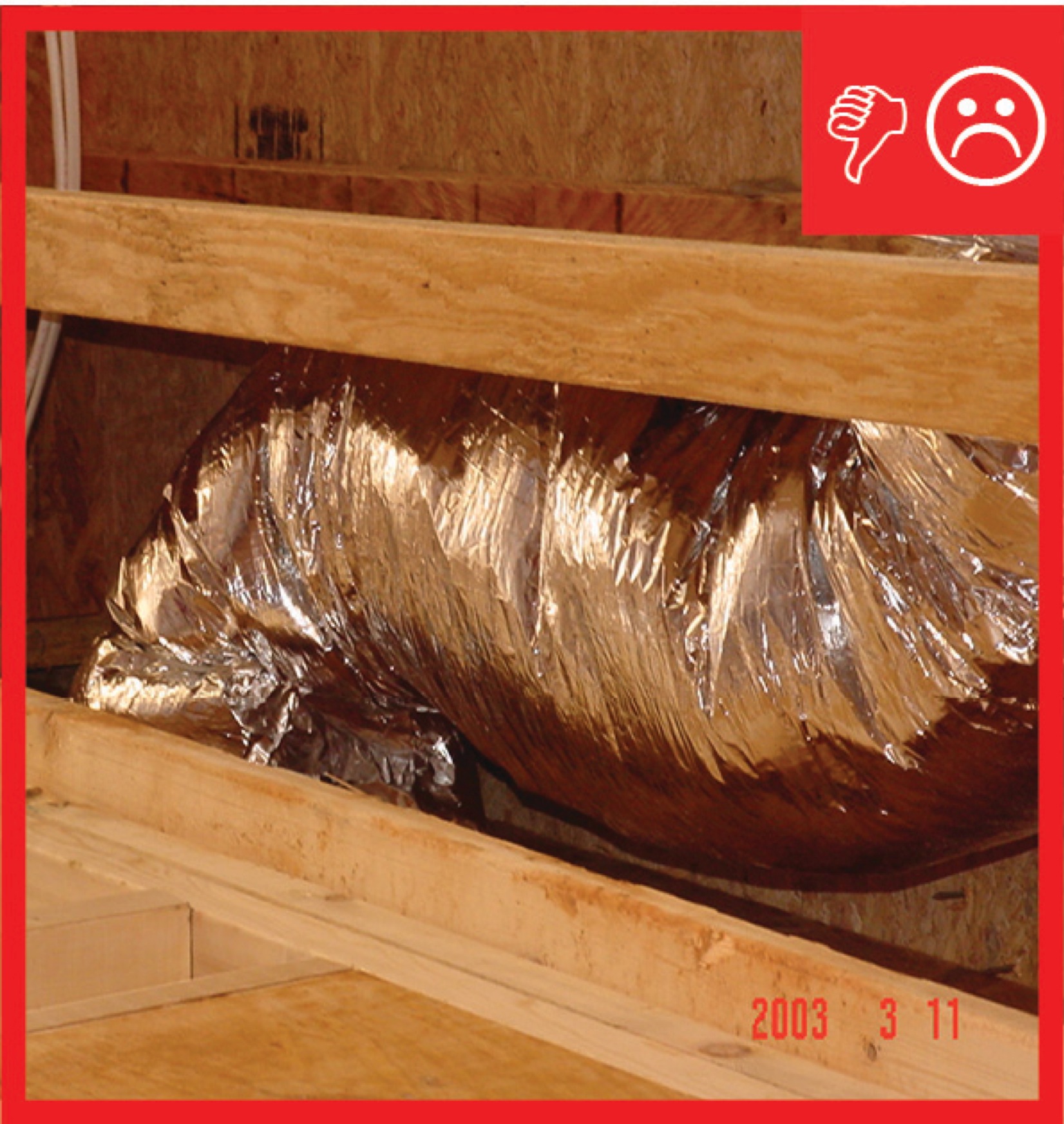
- Avoid installing excessive lengths of flex duct; flex duct should be stretched taut when installed correctly.
See the Compliance Tab for links to related codes and standards and voluntary federal energy-efficiency program requirements.
Description
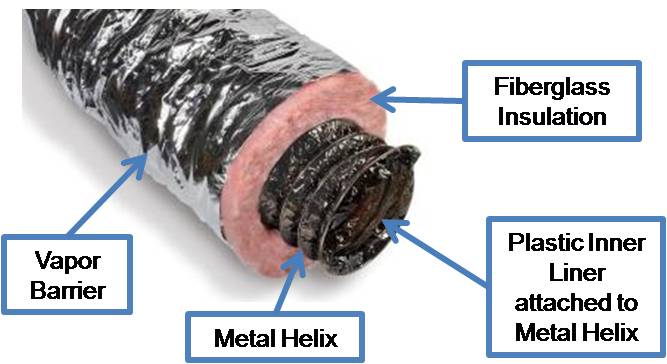
Flexible ductwork, known as flex duct, is very convenient ducting for attaching supply air outlets to rigid trunk ductwork. In many cases, flex duct comprises the complete duct system. Flex duct made for HVAC applications is typically constructed of a plastic inner liner attached to a metal wire helix (or coil) to make round, flex duct. The duct comes with a layer of fiberglass blanket insulation already attached around the duct. The insulation is covered and protected by a polyethylene or foil vapor barrier. Flex duct is typically available in insulation values of R-4, R-6, and R-8. For residential HVAC systems, insulated flex duct typically comes in diameters of 4 inches through 10 inches; above 10 inches, it comes in even sizes of 12, 14, 16, etc., up to 22 inches measured at the radius of the metal helix.
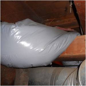
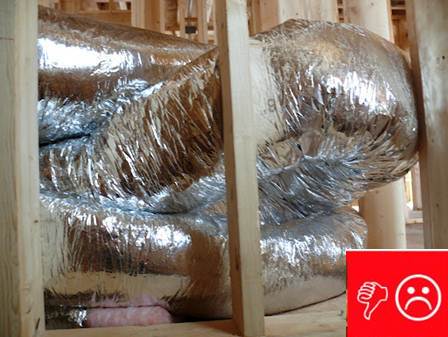
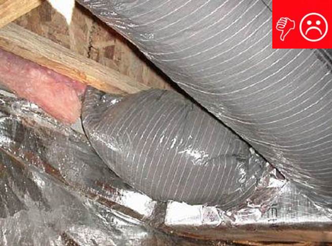
Insulated flex duct, if installed to the standards described in Manual D Residential Duct Systems (Air Conditioning Contractors of America [ACCA] 2009), can be a cost-effective air duct product. Flex duct bends easily to accommodate turns around slight obstructions. This flexibility is flex duct’s greatest asset and its greatest liability. Because it bends so easily, there is a temptation to ignore HVAC layout in framing designs. Then, when HVAC is installed after framing, the ducting may be bent or compressed excessively to fit around obstructions. Compressions restrict air flow to affected rooms and increase pressure on the system fan, causing premature wear and excessive energy use. For a better understanding of HVAC fan static pressure and pressure drop in HVAC systems, see Supply Return Static Pressure.
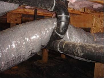
The routing of flex duct, the number of bends, the degree of the bends, and the amount of sag between supports will negatively affect the overall pressure drop across the duct system because of the increased resistance. When a bend or turn has to be made in the flex duct, avoid bending across sharp corners and do not exceed 90-degree turns. Use gradual curves instead. Avoid incidental contact with metal fixtures, pipes, or conduits, especially in humid climates where compressed insulation can create condensation issues.
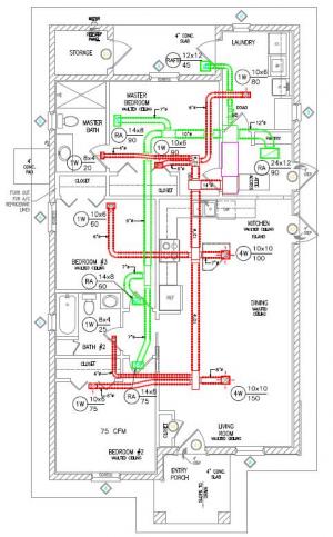
The best way to avoid conflict between the HVAC duct system and other services like plumbing and wiring is to plan for HVAC system layout in the initial design stage. Figure 4 shows a compact duct design with short runs and minimal turns.
The Manual D friction rate method requires estimating the equivalent length of the duct system. The equivalent length of duct is based on the design velocity. Bends and junction boxes increase friction in the duct. To account for this friction, ACCA has determined numerical values in feet of equivalent length that can be added when estimating the length of ducting in the distribution system. For example, a 90-degree bend in a flex duct adds an additional 15 feet of equivalent length to the duct system at a velocity of 700 feet per minute. (See Manual D, Third Edition, Appendix 3, Group 11, "Flexible Duct Junction Boxes and Radius Bends," [ACCA 2009].)
Manual D Residential Duct Systems (ACCA 2009) sets standards for flex duct design and installation. See Appendix 17 for a detailed discussion of duct installation. The Flexible Duct Performance Standards (Fifth Edition) by the Air Diffusion Council (ADC) provides guidance to designers, architects, engineers, contractors, and installers.
For more on flex duct installation, see No Excessive Coiled or Looped Flex Ducts, Sufficient Cavity Space for Flex Ducts, Support at Intervals for Flex Ducts, and Sealed and Insulated Flex Ducts.
How to Install Flex Duct without Kinks and Bends:
- During the design phase, perform a room-by-room Manual J HVAC load calculation to identify the required airflow for each room.
- Using preliminary construction documents, lay out or sketch possible duct routing on floor plans. Lay out the ducts so that runs are as short and straight as possible. Review sectional drawings for possible obstructions.
- Perform a Manual D calculation on the proposed sketch. Make the Manual D duct design part of the construction documents. If flex duct is run through manufactured trusses, there will be bends and they should be calculated as elbows.
- At the duct-to-boot connection, consider using a metal duct elbow or a plastic duct bend support product to reduce the risk of a kink at the duct-boot connection. When installing, pull ducting taut to avoid sagging as described in No Excessive Coiled or Looped Flex Ducts.
- Before the framing stage, consult the design team, discuss duct routing, and determine the work flow to minimize conflict with other trades. If HVAC ducts are installed before plumbing and electrical, discuss expectations about avoiding compression of ducts with those trades.
Ensuring Success
Make sure that duct chases are considered early in the home design phase. Use ACCA Manual D procedures for designing flexible duct systems (See Manual D, Section 11, Sizing Flexible Constant Volume Duct Systems). Inspect installed ductwork during the thermal bypass inspection to ensure there are no sharp bends or kinks.
Region
No climate specific information applies.
Training
Right and Wrong Images
Videos

Retrofit
SCOPE
Additions: If new flex duct is added to an existing home, either as part of an HVAC system upgrade or a building addition, ensure that the flex duct is installed in runs that are as short, straight, and direct as possible, with no kinks or sharp bends, as described in the Description tab.
Existing Buildings: In an existing building with flex ducts and an under-performing HVAC system, inspect for kinks or sharp bends in the flex duct. Symptoms may include minimal air flow to a terminal, excessive noise, or fan burnout due to increased static pressure.
If the ducts are located in the attic, review the guide Pre-Retrofit Site Assessment of Ceilings, Attics, and Roofs.
If the ducts are located in the basement or crawlspace, review the guide Pre-Retrofit Site Assessment of Crawlspaces and Basements.
For more information about ducts see the U.S. Department of Energy’s Standard Work Specifications.
DESCRIPTION
For the installation of flex duct in retrofit and existing building situations, follow all best practices and precautions described for new construction.
Additions
See Pre-Retrofit Assessment of Existing HVAC Systems for a discussion on when and how to add spaces to an existing distribution system. Coordinate the duct layout for a new space with the design of the structure and other systems to ensure there is space for proper routing of the ducts. As with new construction, use ACCA Manual D and provide a schematic of the layout to the home owner for future reference.
Existing Buildings
See Pre-Retrofit Assessment of Existing HVAC Systems for a discussion of how to determine whether a flawed duct design may be contributing to poor HVAC system performance. If flex duct is found to be crushed, kinked, bent, pinched, or otherwise compromised, the duct must be fixed and the routing adjusted to provide a path of full-diameter opening for the entire run from the branch takeoff to the register (see the Description tab of this guide). Sometimes it will be necessary to remove drywall to reach the flex duct. Where space within or through existing structures cannot accommodate the full diameter of the duct, there are two alternatives:
- Consider adding one or more additional registers then routing the required airflow to the room through multiple smaller ducts that fit better in the available space. This approach may provide better coverage for the room at reasonable friction drops that can still allow the fan to operate efficiently.
- Consider a new location for the register that will allow an unobstructed path and still provide good coverage for the room. This will require moving the room’s register to a new location and patching the drywall in the previous location.
SUCCESS
When re-routing ductwork, access the ducts directly from the basement, crawlspace, or attic if possible. If the ducts are behind finish materials like drywall it is tempting to make the smallest possible openings in existing ceilings and walls in an effort to reduce disruption. However, flex duct is likely to collapse if forced into place from a distance. It will be impossible to fully examine the entire duct layout if openings are too small. Instead, cut openings in drywall large enough to fit the head and shoulders of the installer so that the flex duct can be manipulated into the best possible orientation. Use ample hangers to hold the duct in place and be sure to open the ceiling directly below any connections that must be adjusted so that collars or strapping can be examined from all directions to ensure a tight seal.
If flex ducts are disconnected to route around obstacles, when reattaching them, fasten the inner liner to the collar with mechanical fasteners and seal with tape or mastic. Cover with insulation and a plastic sheeting vapor barrier and seal the plastic to the trunk duct or boot collar with metal tape or mastic, as described in the guide Sealed and Insulated Flex Ducts.
CLIMATE
Although an existing duct system is generally not required to be brought up to code when making repairs (double check this with the local code official), you can take this opportunity to check the ducts for duct leakage and seal all accessible seams and joints; use outward-clinched staples and UL-181A-approved metal tape that is heat activated or pressure sensitive, or use mastic and fiber mesh tape. You can also add duct insulation where it is lacking or deficient, especially if you see evidence that condensation has been occurring. Starting with the 2009 International Energy Conservation Code (IECC) supply ducts located in unconditioned space must be insulated to at least R-8 and return ducts must be insulated to R-6.
In humid climates, uninsulated or under-insulated ducts in unconditioned space can create a source of moisture damage. When warm, humid air comes in contact with the cold surface of a duct delivering chilled air, the water vapor can condense to liquid water that can cause rust in the ducts and mold in insulation, framing, and other building materials. See Sealed and Insulated Flex Ducts for detailed guidance.
COMPLIANCE
See Compliance tab.
More Info
References and Resources
*For non-dated media, such as websites, the date listed is the date accessed.
Contributors to this Guide
The following authors and organizations contributed to the content in this Guide.
Sales
Proper Duct Installation = Professionally-Installed Comfort Delivery Ducts
Technical Description
Conditioned air is often lost in transition from comfort equipment to living spaces because of poorly designed duct layouts and poor installation practices, which cause homeowners to pay for conditioned air that never reaches the living spaces of their home. Poor duct layouts with overly long duct runs, numerous branches, and sharp bends, and poor installation with sagging, twisted, or crushed ducts, can severely limit air flow, reducing system performance and increasing energy costs. Professionally installed comfort delivery systems should be installed with compact duct layouts featuring short, straight duct runs with properly supported ducts, in accordance with industry standards. The ducts should be properly insulated, completely air sealed, and free from kinks and sharp bends that restrict air flow.
Questions? Comments? Contact our webmaster.