

Scope
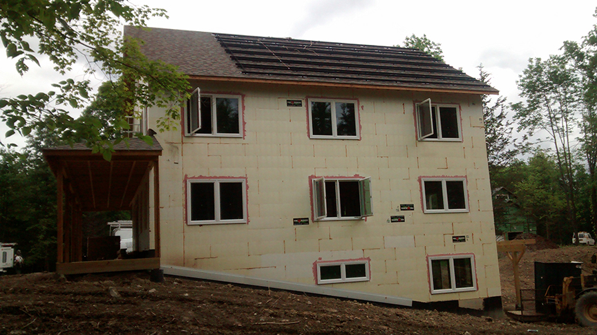
Construct exterior walls with insulated concrete forms (ICFs) that provide insulation without thermal bridging, as well as air sealing, a drainage plane, and high structural strength.
- Install ICFs according to manufacturer’s specifications to provide a continuous air barrier and thermal boundary.
- Seal all seams according to manufacturer’s specifications to provide a weather-resistant barrier and drainage plane.
See the Compliance Tab for links to related codes and standards and voluntary federal energy-efficiency program requirements.
Description
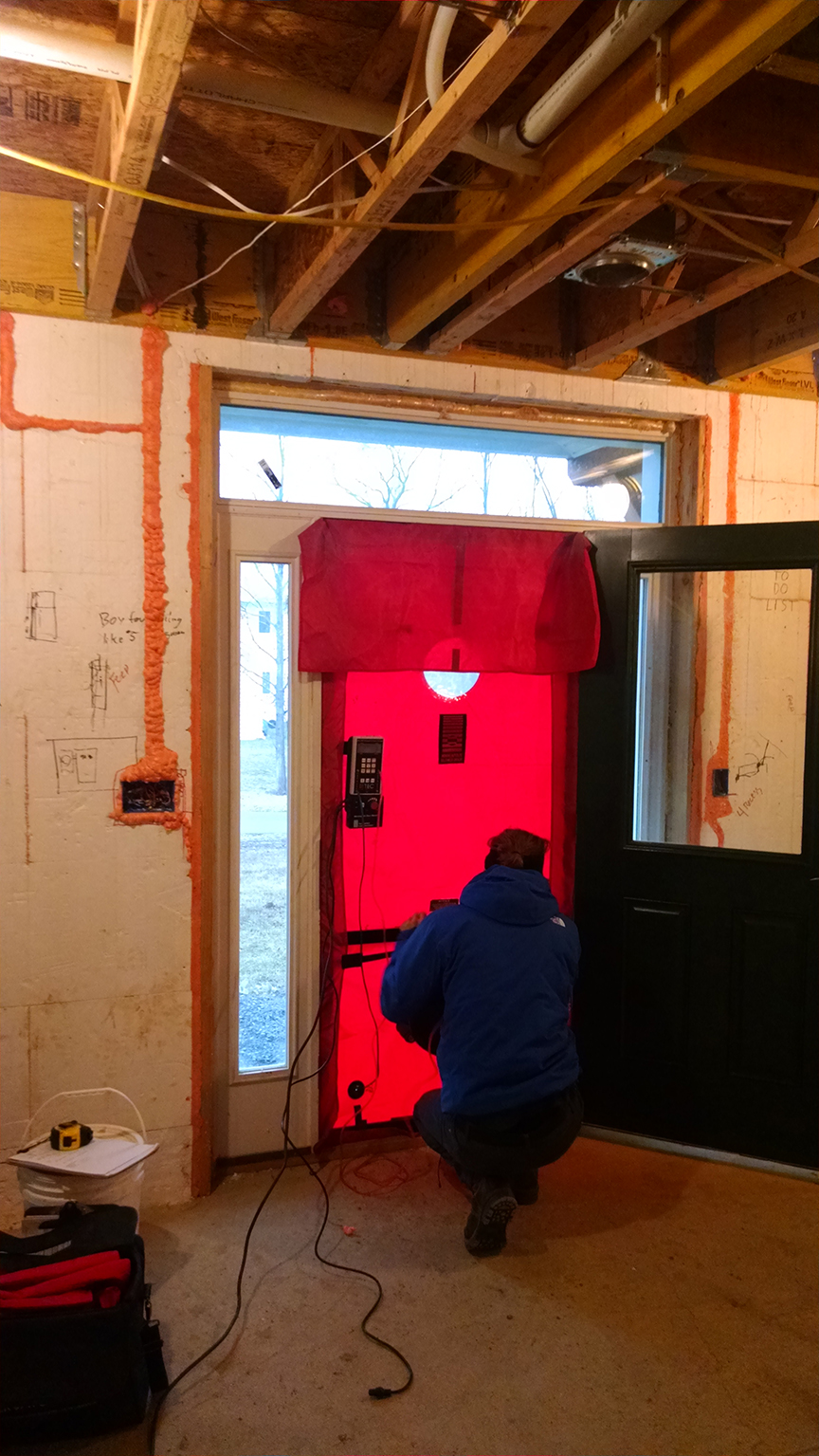
Insulated concrete form (ICF) construction combines concrete and rigid foam for walls that are thick, sturdy, and continuously insulated. Studies comparing ICFs with stick-frame construction have shown that in otherwise identical homes, the ICF houses had a 9% better whole-wall R-value and were 10% more airtight (Christian 1996). ICF walls have almost no thermal bridging in the wall itself and, with proper design details, thermal bridging can be almost eliminated at the rim joist as well (Petrie et al. 2003; Desjarlais et al. 2002).
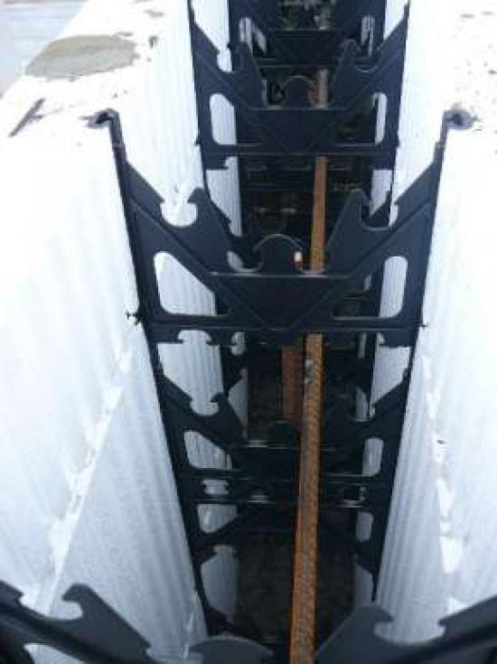
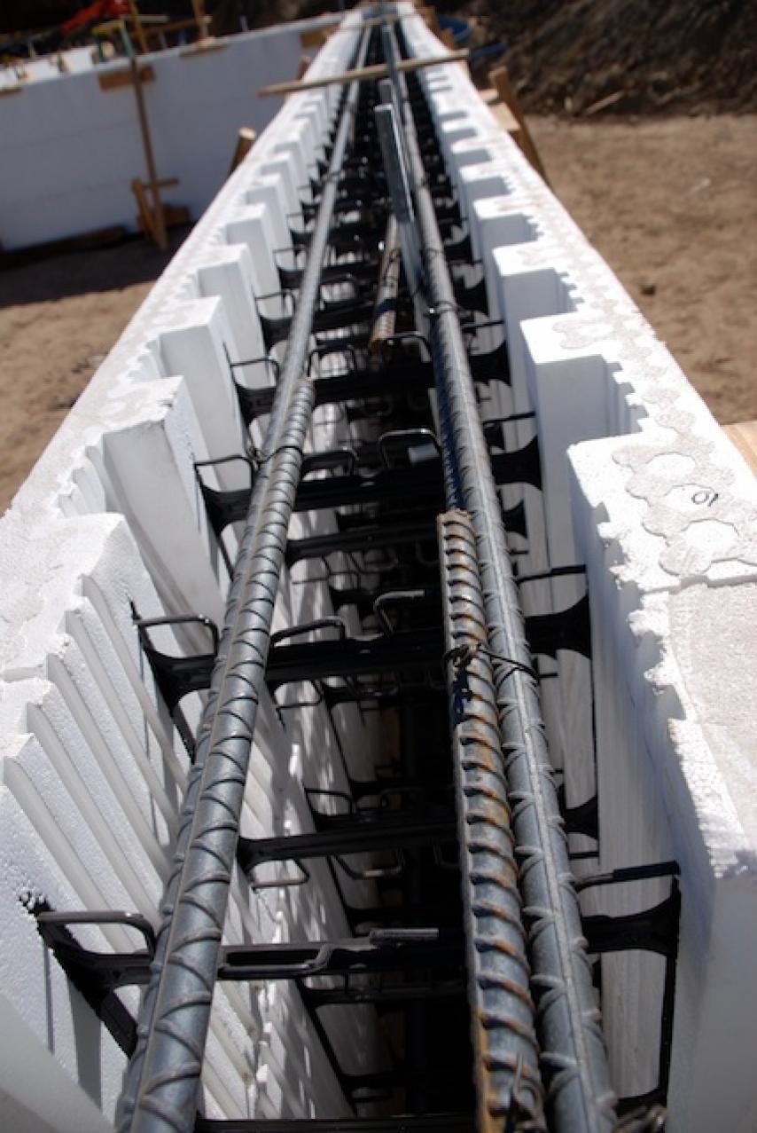
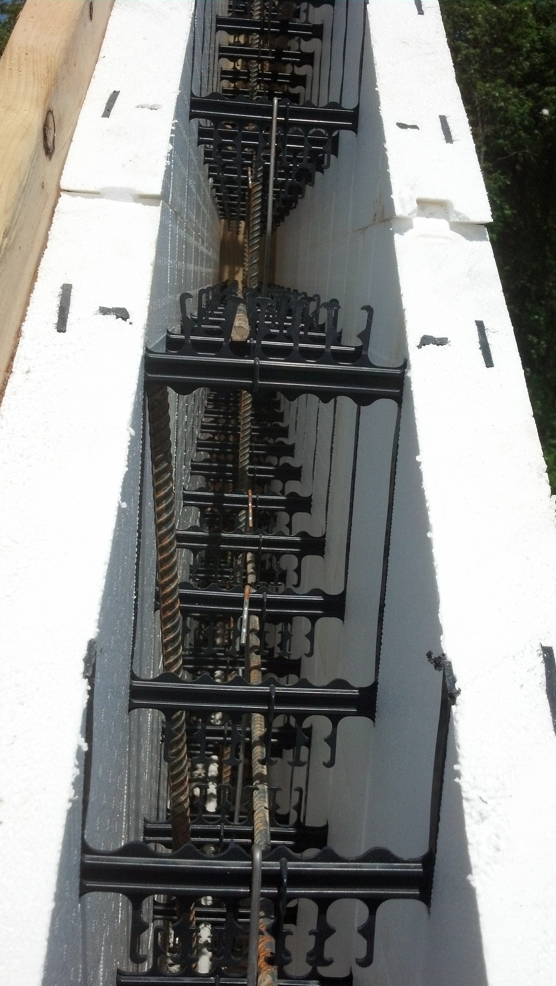
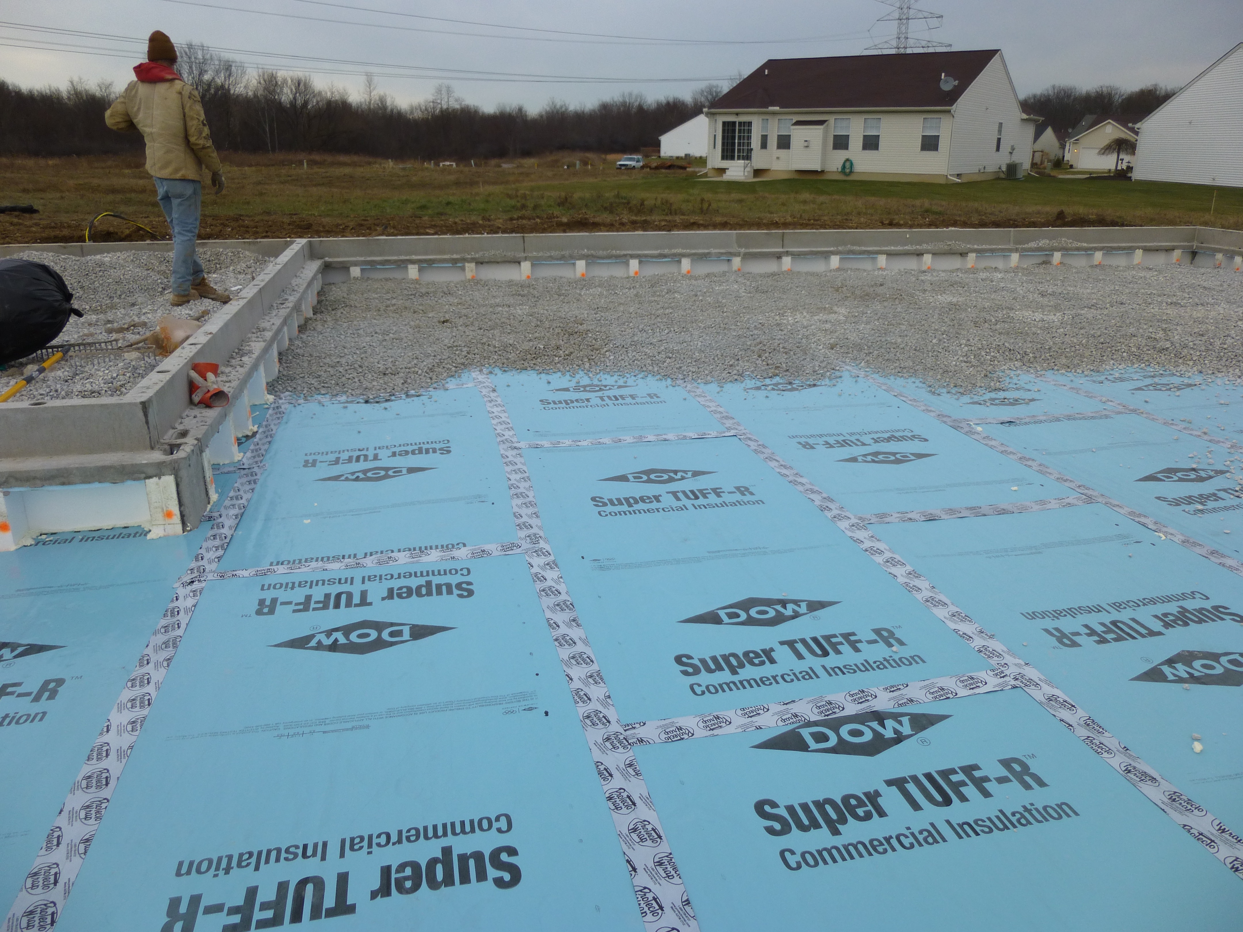
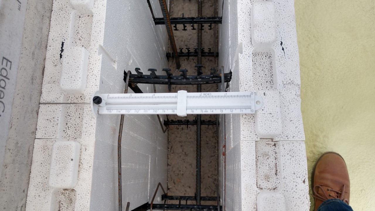
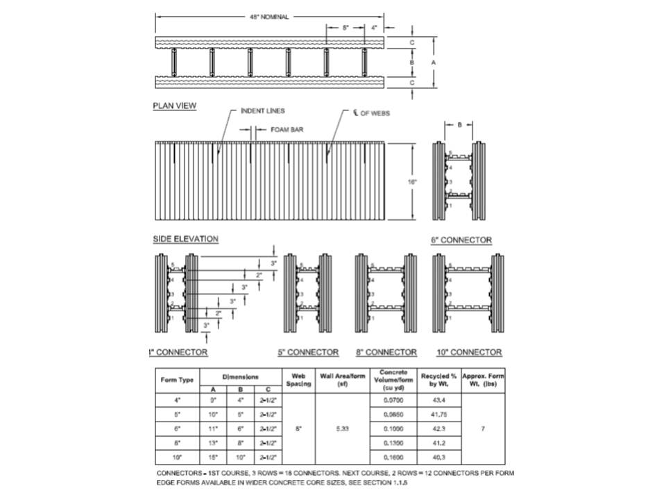
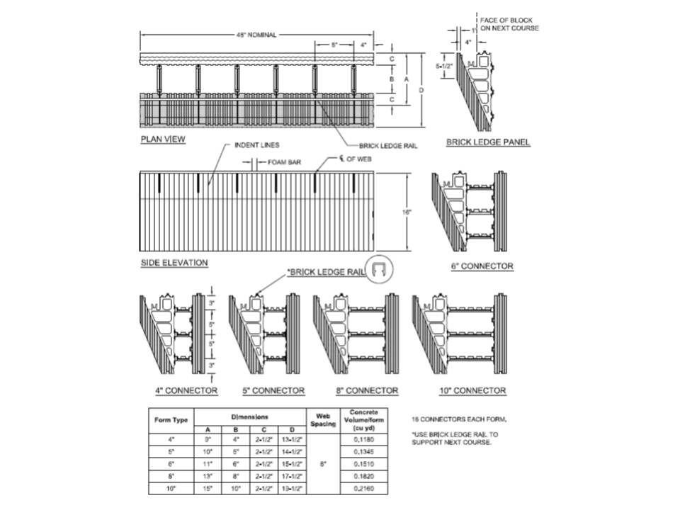
ICFs are typically made of pre-molded blocks or panels of rigid foam, which are assembled on site to create wall forms into which concrete is poured (Figure 1). The foam forms stay in place, providing permanent insulating foam layers on the interior and exterior of the wall. Foam blocks are typically comprised of two 2-inch-thick, 16 by 48-inch rectangles of foam that are connected by plastic, metal, or foam ties. The ties hold the foam panels 6 or 8 inches apart during the pour and remain in place afterward. The blocks are stacked like bricks to create the wall forms for the concrete. Steel rebar is added to the cavities for additional strength (Figure 2). Some ICFs come with plastic nailing strips embedded in their exterior surfaces. The foam is typically expanded polystyrene (EPS). Some ICF products use extruded polystyrene (XPS) foam, which is stronger but more costly. A few products are made with recycled foam or wood. Some ICF walls consist of two layers of concrete sandwiching a central layer of foam.
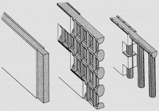
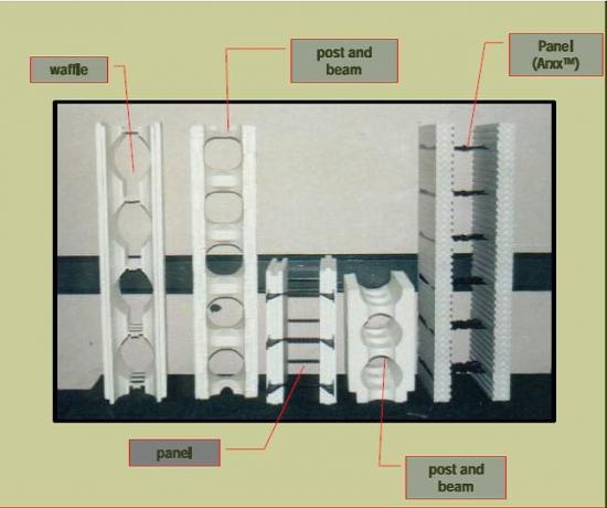
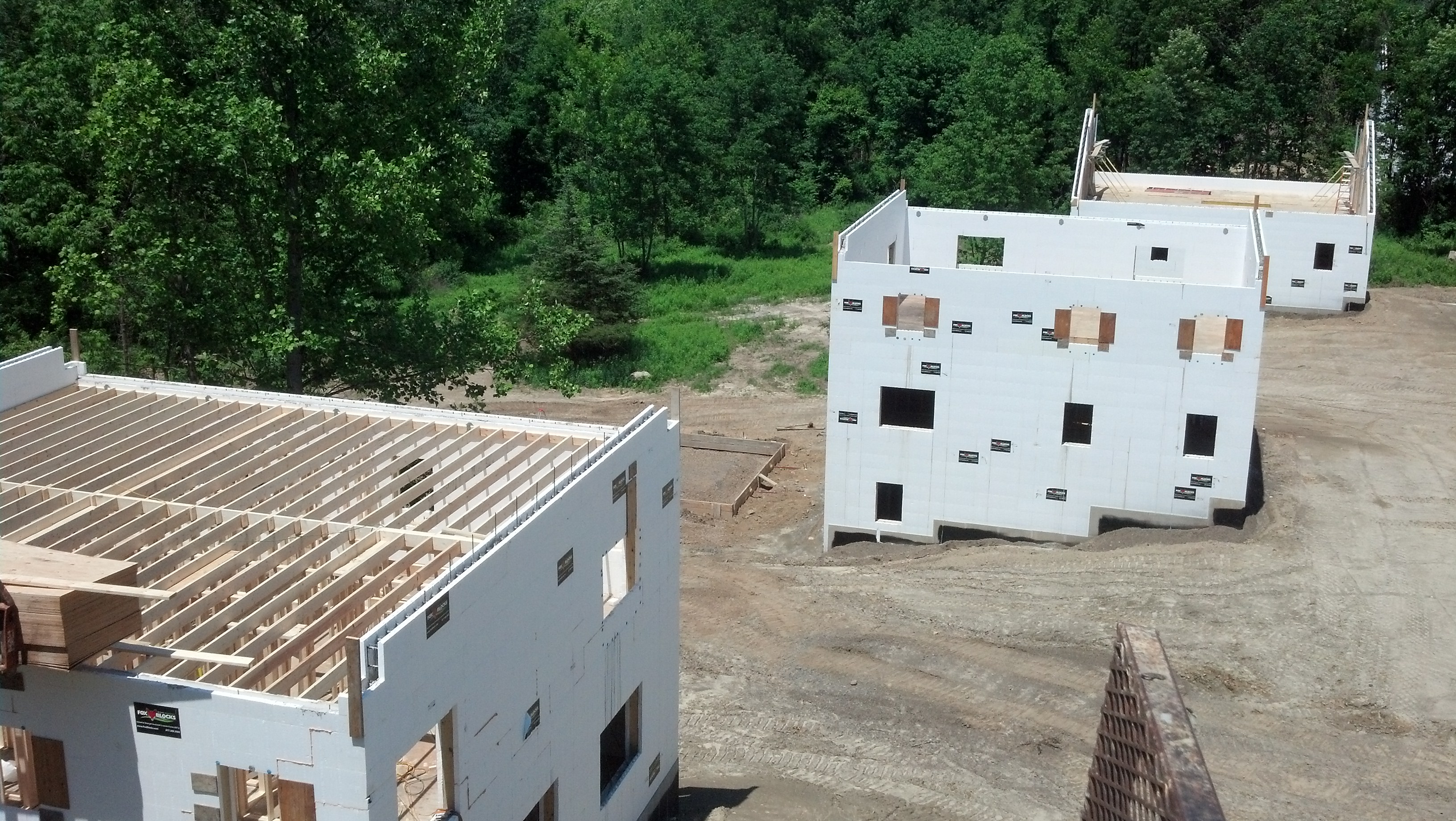
Common types of ICF walls are shown in Figures 3 and 4. A flat ICF wall system is a solid concrete wall of uniform thickness with sheets of insulation forming the interior and exterior surfaces of the system. The waffle-grid ICF wall system is a concrete wall composed of closely spaced vertical (maximum 12 inches on center) and horizontal (maximum 16 inches on center) concrete members with concrete webs between the members. The screen-grid ICF wall system is similar to a waffle-grid ICF wall system without concrete webs in between the vertical and horizontal members. The post and beam ICF wall system has vertical and/or horizontal concrete members spaced farther than 12 inches on center.
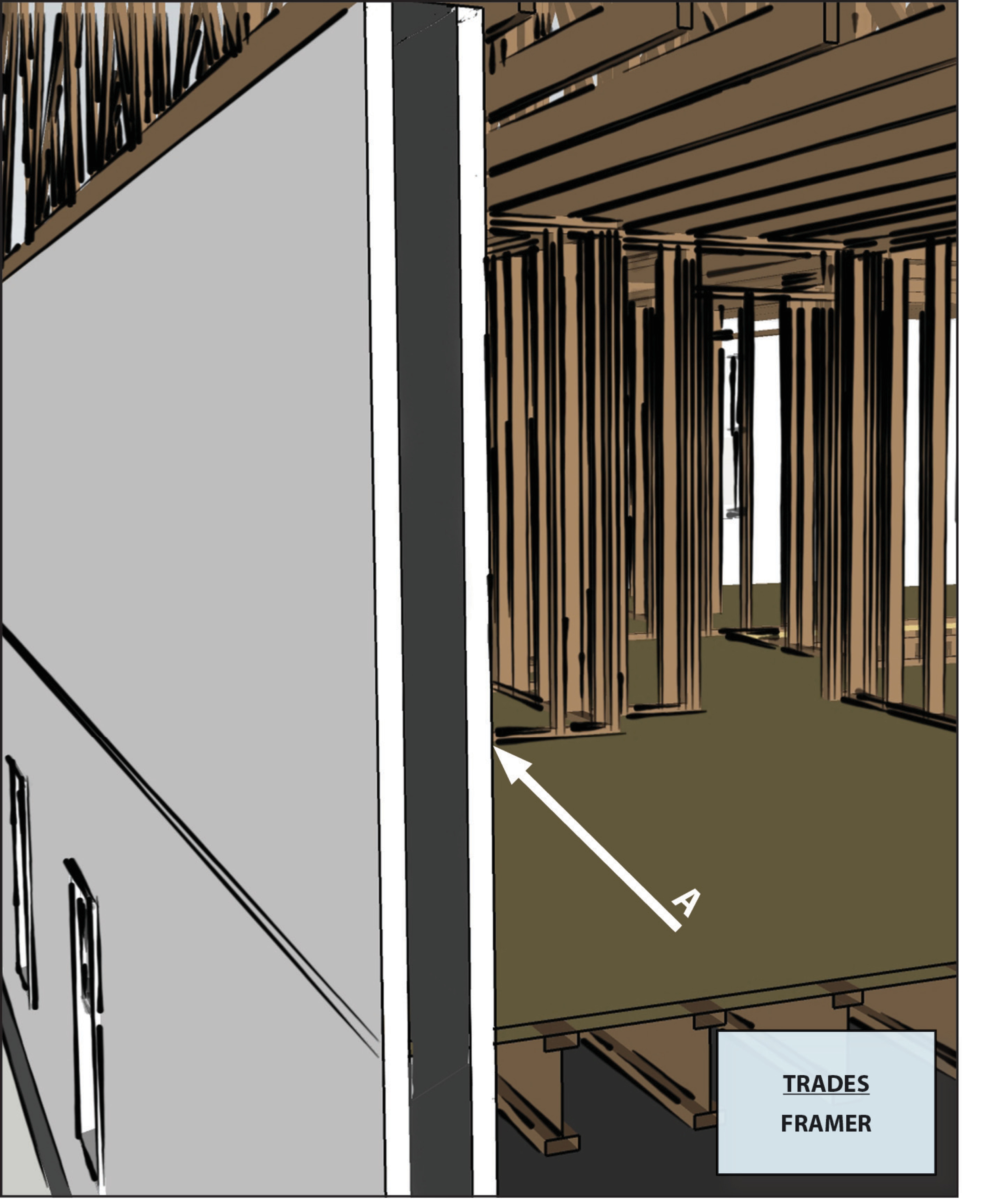
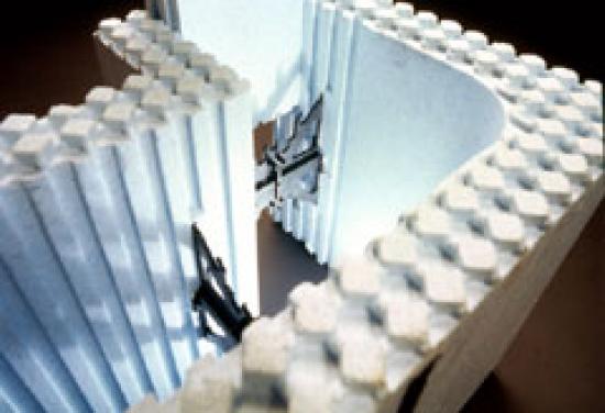
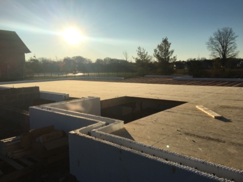
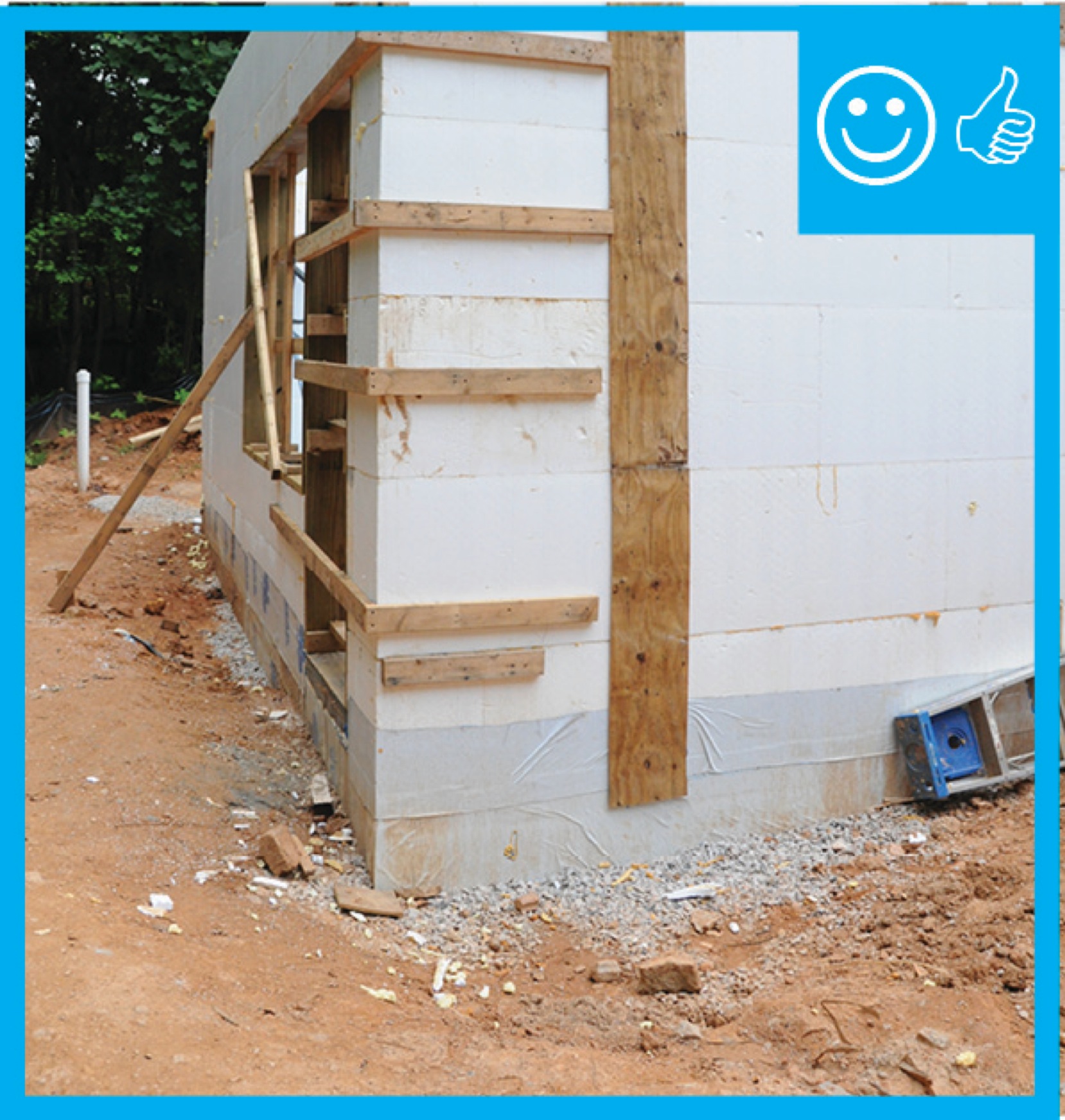
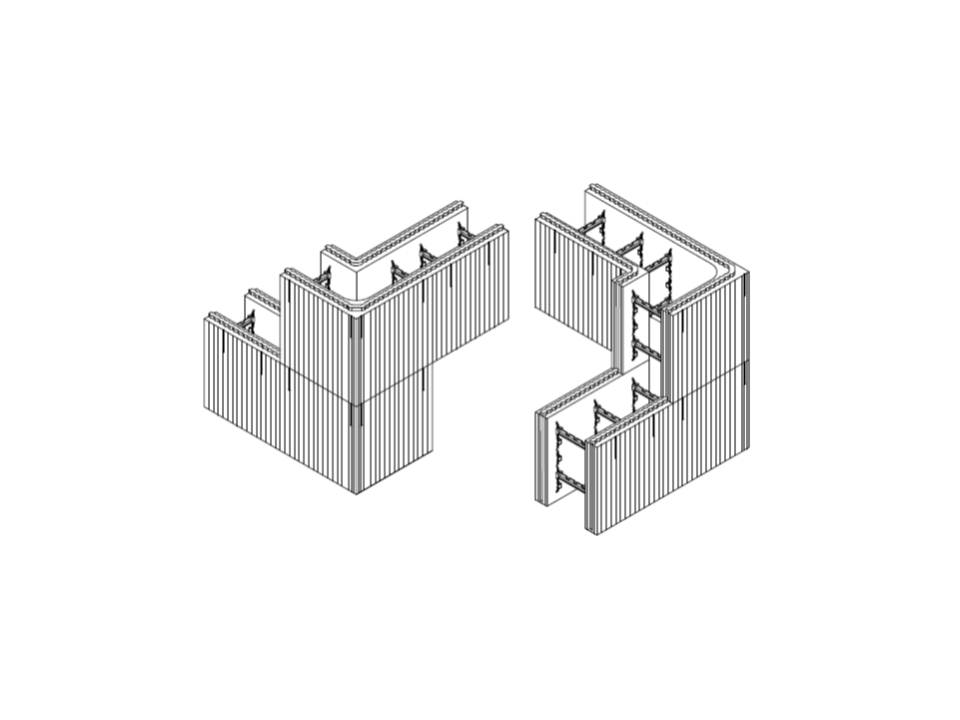
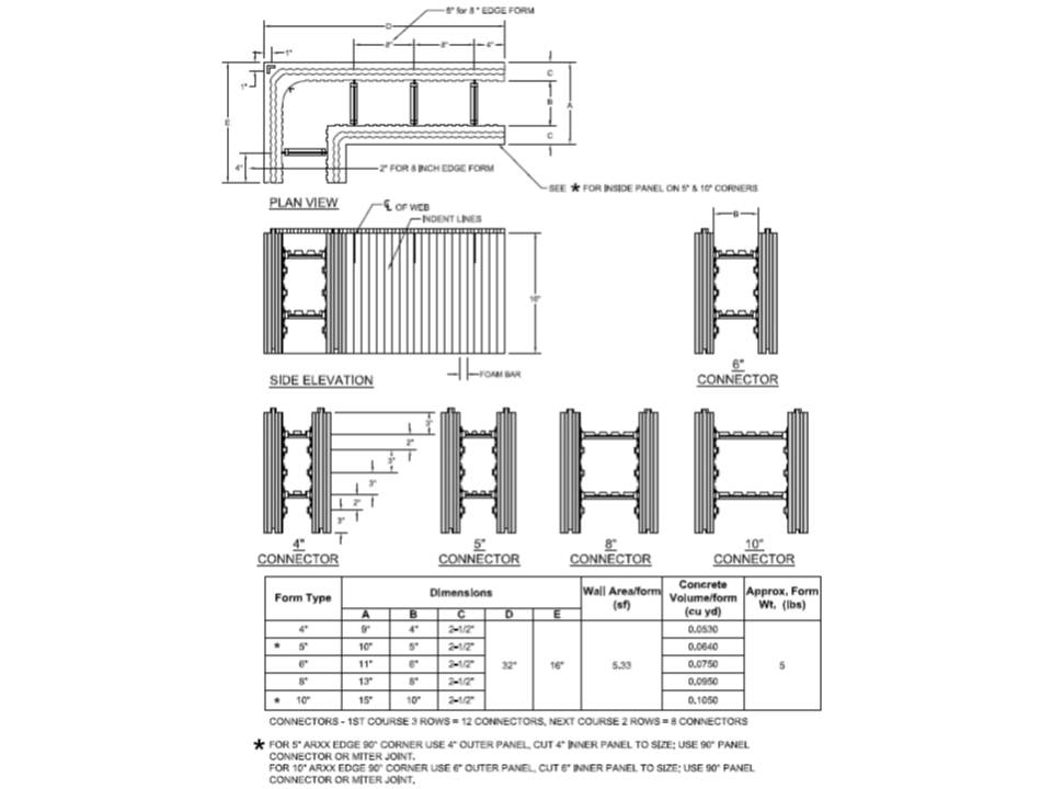
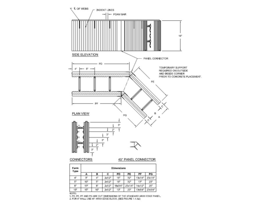
ICF systems are installed in a manner similar to masonry, starting at the corners and placing a layer at a time to build up the wall. Most manufacturers make specifically molded corner blocks that provide a continuous layer of foam around the corner to reduce thermal bridging there (Figure 5). Window and door openings must be framed with lumber (Figure 6). Lumber blocking is also needed where bearing pockets are required for floor or roof supports. Ledgers can be mounted to the blocks for attaching floor framing.
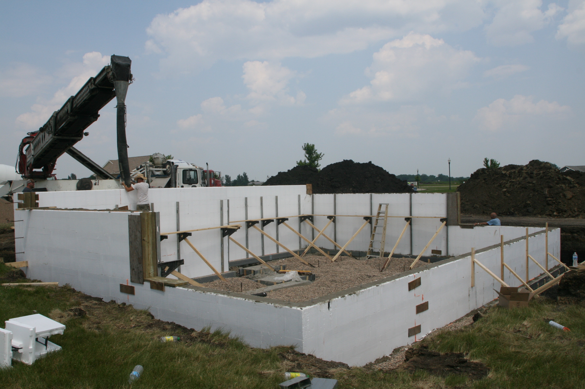
Once the forms are in place and braced, and required reinforcement is installed, concrete is pumped into the forms (Figure 7). Even with the bracing, the forms need to be filled at an appropriate rate based on the ICF manufacturer’s recommendations to prevent misalignment and blowouts. Form failures are rare when the manufacturer’s recommendations are followed. Reinforcement in both directions maintains the wall strength. For earthquake-prone areas, reinforcement should be designed per seismic design requirements. A good item to have on hand when the concrete arrives is a blowout repair kit. Unless a self-consolidating concrete mix is used, concrete should be vibrated after pouring to remove trapped air as air pockets can lead to thermal bridging and weaken the cement (ICF Builder 2012).
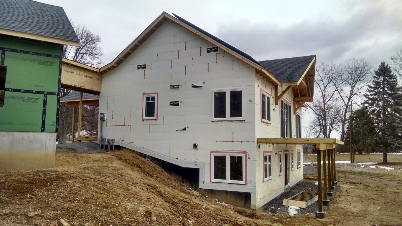
Depending on the specific system, the walls may allow attachment of exterior and interior wall coverings directly to the wall with little or no modifications to the wall. After finishes are applied inside and out, typical final wall thickness is greater than 1 ft. This means that window and door surrounds may be wider than is typical for frame construction, resulting in deeper window sills.
How to Install ICFs
Stacking (NAHB 2001)
- Place dowels (rebar) in footings, foundation wall, or slab as required.
- Place temporary braces along the first course to align the ICF forms and to prevent movement.
- Set blocks on concrete footings. Concrete can be recently placed and uncured.
- Place termite shield.
- Complete one course all the way around the building’s perimeter.
- Stagger subsequent courses so that vertical foam joints do not line up from one course to the next. Make sure vertical and horizontal cavities line up. Set horizontal and vertical rebar as required.
- Cut for openings as required (or cut out after entire wall is built).
- Install bucks (2x4 or 2x6 wood framing) around the windows and doors as an attachment surface for windows and doors. A buck may be recessed, protruding, or "channel." Use pressure-treated wood for window framing and all other wooden structural components of the house (ICF Builder 2012, ICFA 2008). EPS foam that is not specifically treated to repel termites is not “resistant” to tunneling termites. EPS provides no food value for termites; however, they will tunnel through it searching for food and a place to live. Alternatively, for window framing, use prefabricated plastic or vinyl bucks. Check all dimensions twice to make sure the rough opening can accommodate the actual window size. Enlarging a rough opening after the concrete has set is costly.
- Place intermediate floor connections and supports.
- Place sleeve penetrations for dryer vents, electrical, HVAC, cable, telephone, solar, and plumbing services, and outside fixtures and outlets.
- Locate and mark block beam pockets.
- Reinforce and support the block brick ledge (if applicable).
Bracing
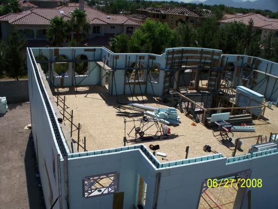
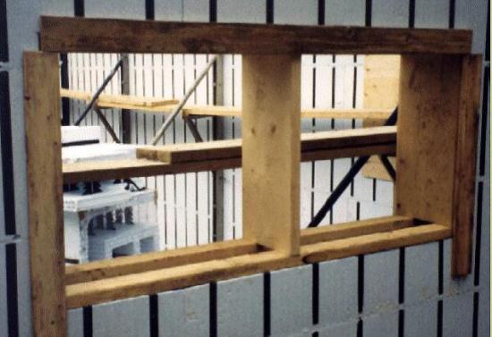
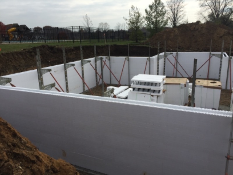
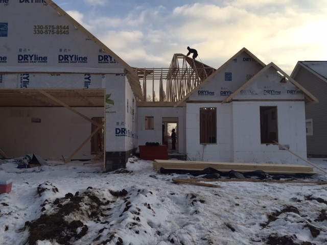
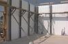
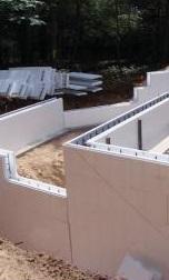
Brace the wall forms every 6 feet with strong temporary bracing to ensure they stay level, plumb, square, and straight during the concrete pour and to support the weight of the concrete until it achieves the desired strength. Bracing is needed at corners, window and door openings, periodically along the length of walls, and at the top of the forms. Window and door bucks are braced inside horizontally and vertically (see Figure 8). Top braces square the forms and provide a surface to check wall height and cut uneven blocks. Follow manufacturer’s recommendations completely.
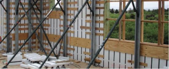
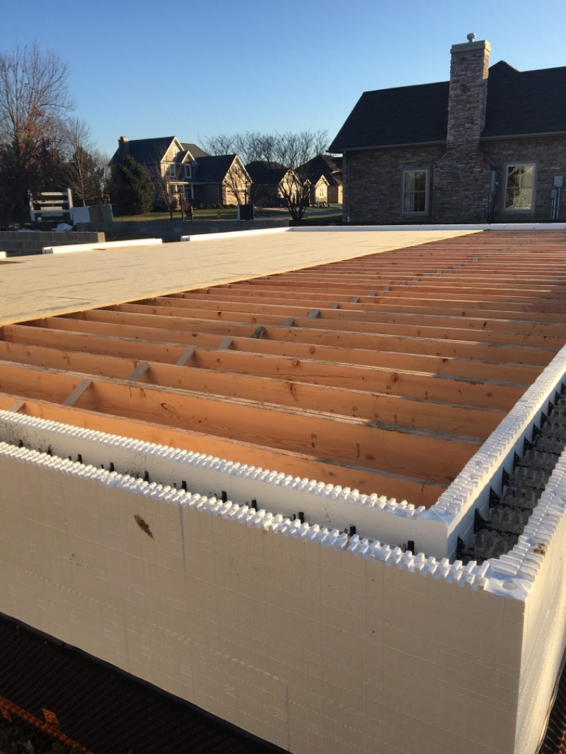
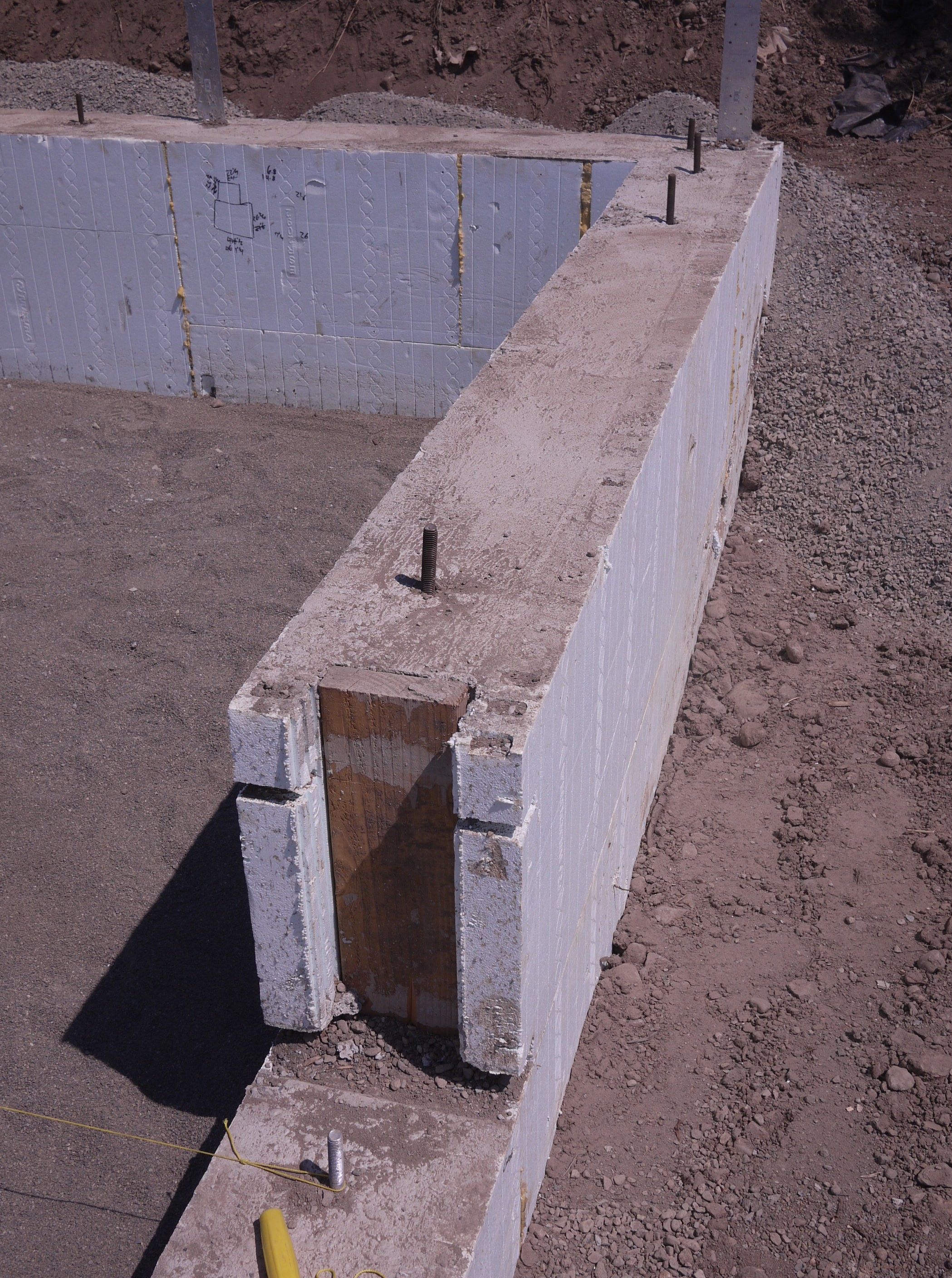
Figure 8. The ICF walls of this home are braced to prepare for pouring the concrete (Source: National Renewable Energy Laboratory). Place anchor bolts and ledgers as required. Floor system attachment options include ledgers, pockets, embedded joist hangers, or direct bearing. Ledgers may be made of wood that is either pressure treated or installed with a water-resistant membrane (Figure 9). Bolts and ledgers are placed before the pour, with foam cutouts around bolts to allow concrete to back up the ledger. (The ledger face must not "bear" only on foam.) Embedded joists require cutting out the foam and inserting wood spacers before the pour to create a pocket in which to seat the joist. Some code authorities also require the embedded joist to be fire-cut. See details provided by manufacturer.
- Place sleeves for any services such as wiring and piping.
Foam seal joints (possibly per course) to secure blocks until concrete is poured and to maintain airtight construction.

Figure 9. Thermal bridging is eliminated at the rim joist with the use of joist ledgers that are anchored in the wall (Source: Building Science Corporation).
Pouring (ICF Systems 2013)
Go through the pre-pour checklist.
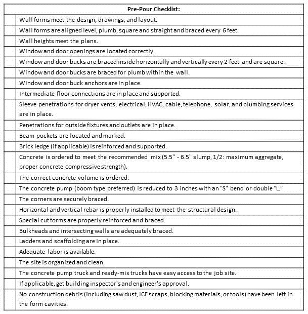
Table 1. Pre-pour checklist. - Confirm the concrete order with the dispatcher.
- Make sure the correct amount of concrete has been ordered, trucks are spaced correctly, and the proper mix design and slump are specified.
- Order a second truck to be shipped when called. Space all subsequent trucks at 45-minute intervals; holding the final truck on call for any adjusted amount.
- When ordering, tell them your order will be pumped, it is for an ICF wall, and that you will have to send back any trucks that arrive with more than a 6.5” slump. Add water if necessary at the site to correct the proper slump.
- Order the correct mix. Work with your ready-mix supplier prior to the pour to make sure they understand the concrete specifications and parameters that ICFs require.
- Choose the concrete pouring equipment.
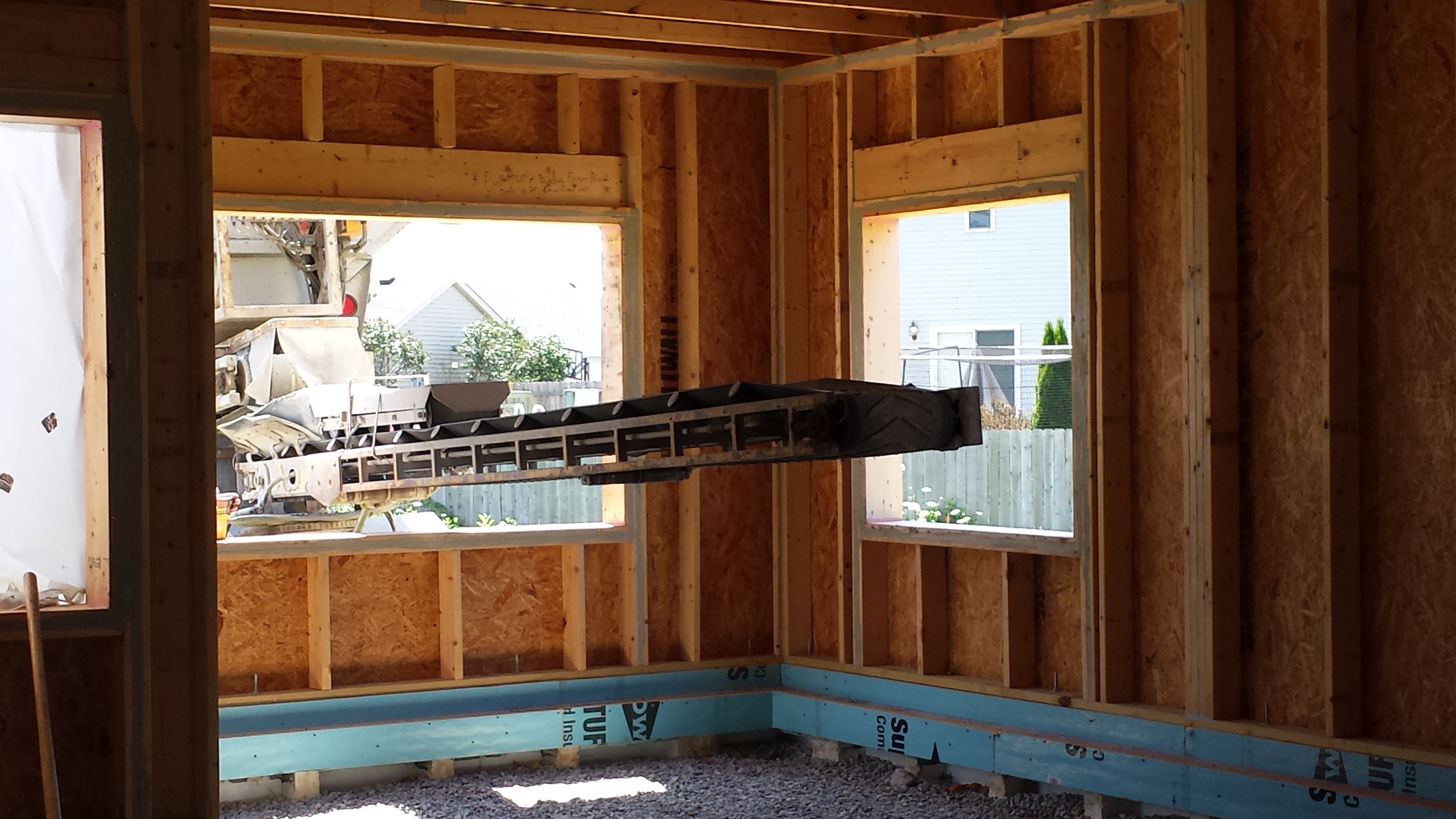
- Use a line pump or a boom pump to place the concrete. Line pumps, also called trailer pumps, are more labor intensive than boom pumps because the hose must be manually moved and lifted into position. The hourly rates for line pumps are much lower than those for a boom pump, but often the total cost is the same, because they take longer to set up, pump, and take down and they require more manpower. Boom pumps, as shown in Figure 10, can get the job done faster if everyone is properly prepared. Boom pumps are specified by their reach. Most residential jobs use 28, 32, or 36 meter booms. If the boom is much longer than needed, place the truck further from the wall to level out the boom and lower the fall of the concrete.
- Reduce the hose width to at least 3 inches. If possible, use an elbow, rams horn, or other attachment at the end of the hose to break the fall and collect the concrete coming through the boom.
- Use a steady pour rate, not pulsing or stopping and starting. It should take about 20 minutes to pour 8 yards of concrete.
Be aware of any overhead power lines when working with boom equipment. Under certain temperature and humidity conditions, electricity can jump from overhead lines to the boom with disastrous consequences. If you have any concern, consult the pump company and request that the local utility company shield the lines during the pour.
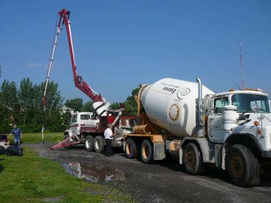
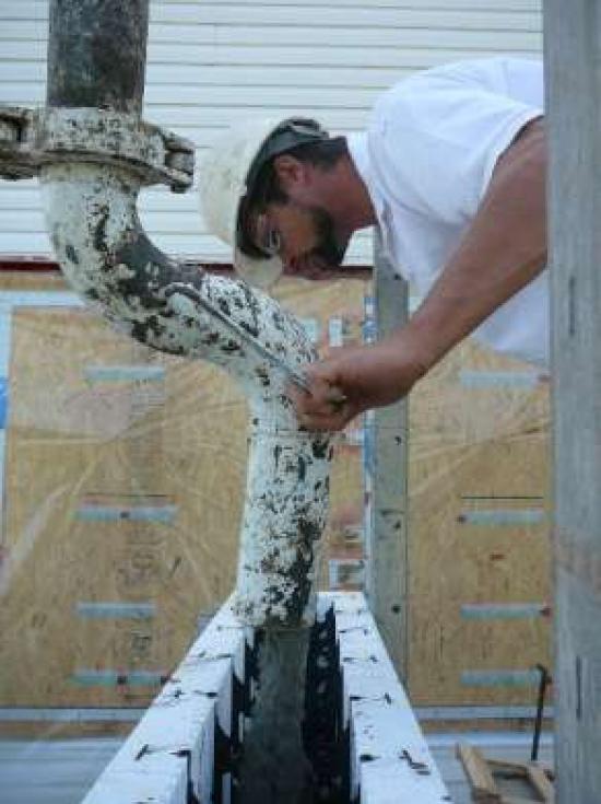
Figure 10. ICF forms are filled with the use of a concrete pumper truck (Source: National Research Council Canada).
- Manage the pour.
- Check the concrete in each new truck when it arrives to make sure that the slump is correct. Make sure the pump operator and each ready-mix driver understand that no water is to be added without your approval. A wetter mix will make their job easier but can impact quality. If the concrete arrives too wet, you have to decide to send the truck back or wait until it tightens up. If you decide to pump, know that you cannot do lifts very high and may have to take more laps around the walls. If you need to increase the slump, one gallon of water will increase one cubic yard of concrete by one inch.
- Be ready to pour when the trucks arrive.
Have adequate manpower on hand. Pump day can be exhausting, don't be light on manpower.
Table 2. Manpower requirements If you are using a boom pump, you will need: If you are using a line pump, you will need: 1 - pump operator 1 - pump operator 1 - hose man 1 - hose man 2 - wall watchers (one inside, one outside) 1 - outside wall watcher 1 - utility person for emergencies, contingencies, straightening wall, etc 1 - utility person 2 - or more hose handlers, rolling scaffolding crew, watching the wall, etc.
Have the right tools on hand. A properly equipped team will make the pour easier, more efficient, and result in a cleaner, more professional, finished product.
Table 3. Equipment Needed Slump cone Gloves Brooms Hardhats 5-gallon bucket Eye protection Plywood for slump test Long sleeved shirts & long pants Trowels Sunscreen Hand tools Shovels Rinsing water - Pour the concrete.
Make sure your scaffolding or walk boards (or other method of getting around the top of the wall) are correct and safe. Raise the scaffolding as needed so the hose man is standing at approximately waist height to the top of the wall. If the top of the wall is above the waist, handling the hose is very fatiguing and the hose man will not be able to see both sides of the wall (See Figure 11).
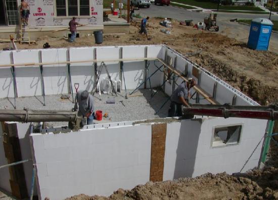
Figure 11. Scaffolding is continually raised as courses of foam brick are added so that that the pour man can see both sides of the wall during the pour. - Have a second person with the hose man to tell him where the concrete is in each section and when to move.
- With the first yard start the fill below a window so you can see the mix and slump; or begin near a corner with a window within 4 feet. Avoid placing concrete directly into the corners. Fill by moving toward the window and watch the concrete fill up to the bottom of the window, then move to the other side of the window starting approximately 4 feet away and fill back toward the window to lock in the other side. As a precautionary measure, you can pump the first yard back into the ready-mix truck and blend it with the 6 or more yards remaining in the mixer, after the pump operator has already primed out.
- Plan to get beyond the 32-in. level (above the seam of the second course of forms) with the first lift. Most houses, up to a 12-foot wall height, will require three passes for a complete fill.
- Have someone trail the hose man to scrape and shake any concrete that may build up on the top of the forms or sit on top of the rebar. This will help prevent voids.
- While filling the walls on the second pass, do not fill too close to the top; stay at least 24 inches down from the top course and do not fill over doors and windows until the last pass. One exception to this rule is that on deep lintels (over 32 inches), you may want to pour a small amount to begin to form the lintel and load the window.
- For the last pass, to the top of the wall, you may want to increase the slump by adding water. The increase in slump will allow you to more effectively fill the top of the wall and will give you more time to trowel the top of the wall and set straps or anchor bolts. Tap or vibrate the outside of the wall for proper consolidation, especially over lintels where extra rebar and stirrups can prevent good compaction.
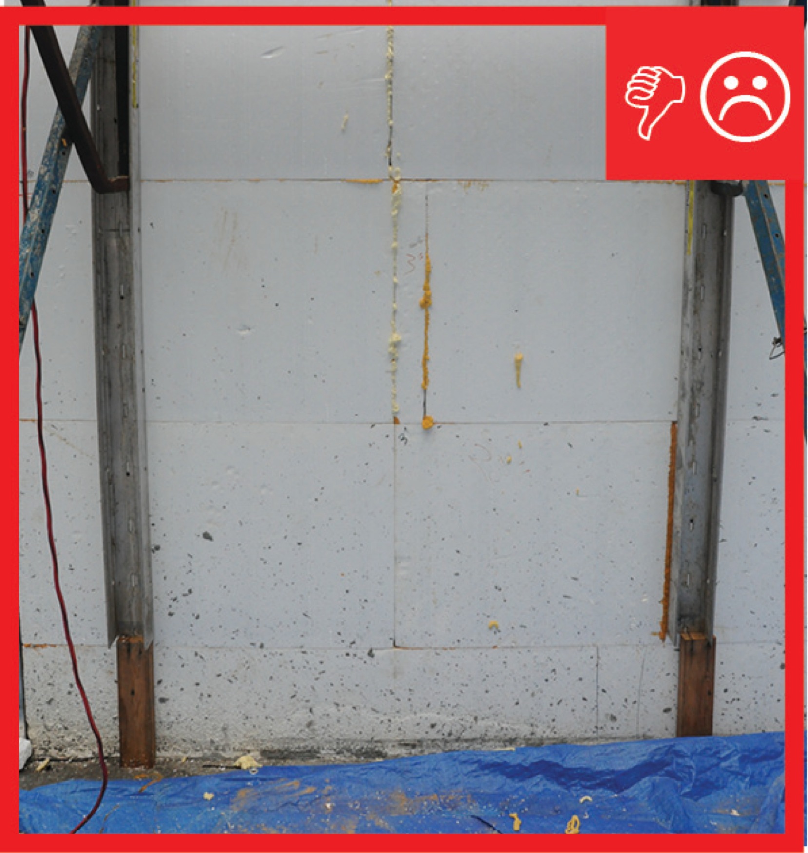
- Fix blowouts.
- Pay close attention when pouring to avoid over-pouring and bulges or blowouts. Blowouts in ICFs are simple to fix. Blowouts often occur where the foam is damaged and not patched or when there is too much water in the cement mix.
- To repair, clean up the spillage and place the broken foam pieces back in the wall. Cover the damaged area with a piece of half-inch OSB and screw the OSB to the furring strips. For larger blowouts, place pieces of OSB on both sides of the wall at the location of the blowout. Clamp them in place with a threaded bar inserted through the wall and both pieces of OSB.
- Perform a final inspection and cleanup.
- Inspect the job to see if you have missed anything.
- Check to see if the walls have moved (the earlier in the pour you notice a bow, the easier it is to correct).
- Confirm that you have good fill. Cross-check the amount of yardage you estimated the walls would require with the load tickets, and know how much yardage you may have left over. Having a yard or two extra is less costly than bringing a truck back with one or two yards.
- Did you over-fill at a door threshold location or forget a beam pocket? It will be easier to dig out the concrete today than it will be tomorrow.
Installing Utilities and Attaching Cladding and Interior Finish Material
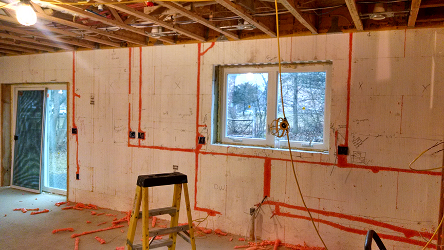
Install wiring and plumbing in recesses cut into the foam after the concrete has been poured (Figure 12). Be sure to cover with metal plates to avoid nailing into wires.
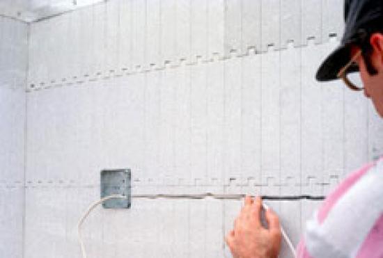
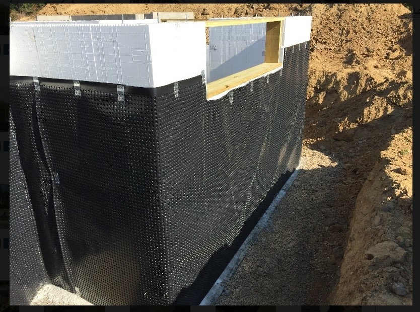
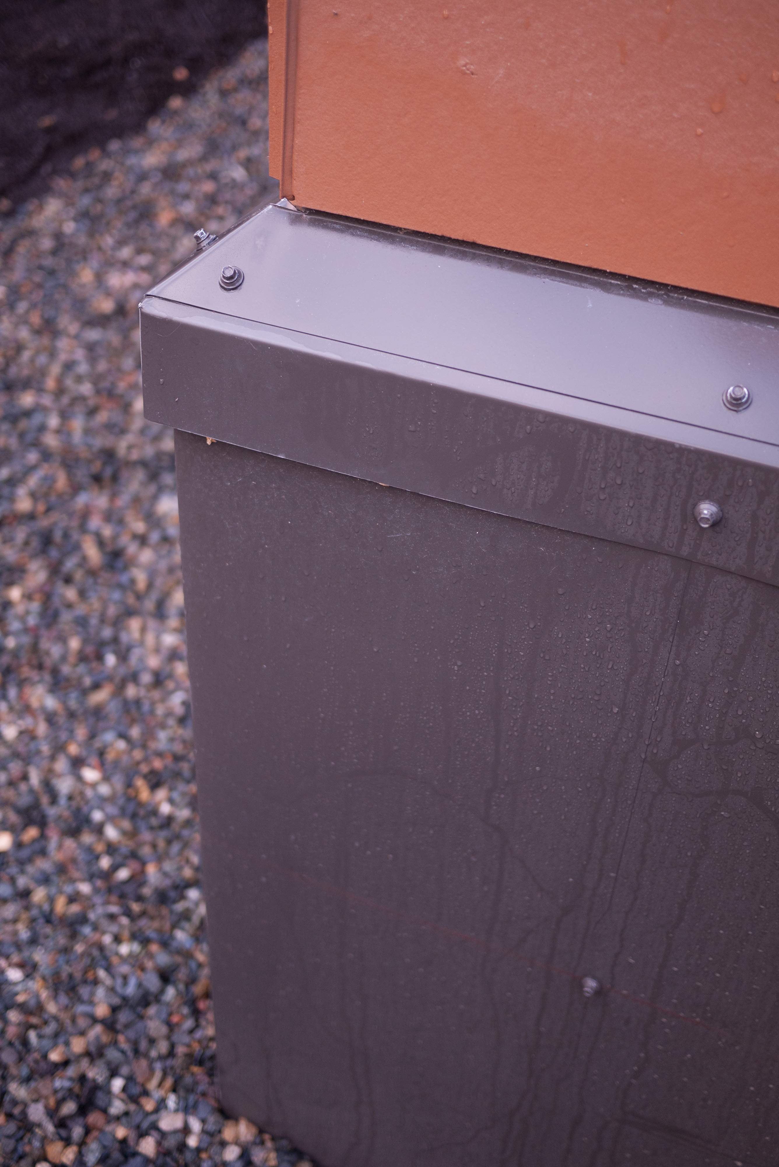
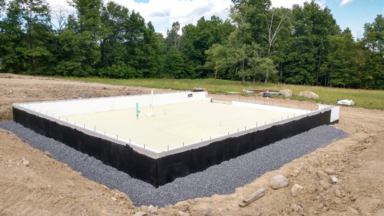
Figure 12. Utilities are commonly recessed into cutouts in the foam after concrete has been poured. (Source: Portland Cement Association.) Apply waterproofing on the exterior side of any sub-grade structure to prevent water intrusion (see Figure 13).
Figure 13. Install waterproofing on portions of the ICF that will be below grade. The waterproofed R-25 ICF blocks shown here are installed starting 30 inches below grade to provide a frost-protected foundation and perimeter insulation for the slab floors of this cold climate home (Source: PNNL). - Attach interior drywall and exterior cladding finishes to the flat ends of metal or plastic ties embedded in the rigid foam. Finishes can also be furred out. Gypsum drywall is the most common interior finish and meets the code requirement for a 15-minute fire barrier over plastic foams surrounding living spaces. Exterior claddings are much more varied but regardless of the cladding type, a drainage layer is recommended between the ICFs and the exterior cladding.
Ensuring Success
Use crews that are trained in insulated concrete form (ICF) construction. Before concrete is poured, the site supervisor should inspect the ICF forms to ensure that they are properly installed and well supported and should measure to ensure that blocked openings are properly sized and correctly placed for doors, windows, penetrations, and mounting elements for floors and roofs. Infrared scans can be performed during construction to verify that the concrete layer is consistent.
Region
Accommodations must be made when pouring concrete in below-freezing conditions, but once in the forms concrete cures slowly and stays hydrated to produce a very strong assembly.
Earthquake-Prone Areas
In areas that are prone to earthquakes, the structure should be built with the appropriate seismic protection. Reinforcing is required for all ICF walls across all Seismic Design Categories.

Training
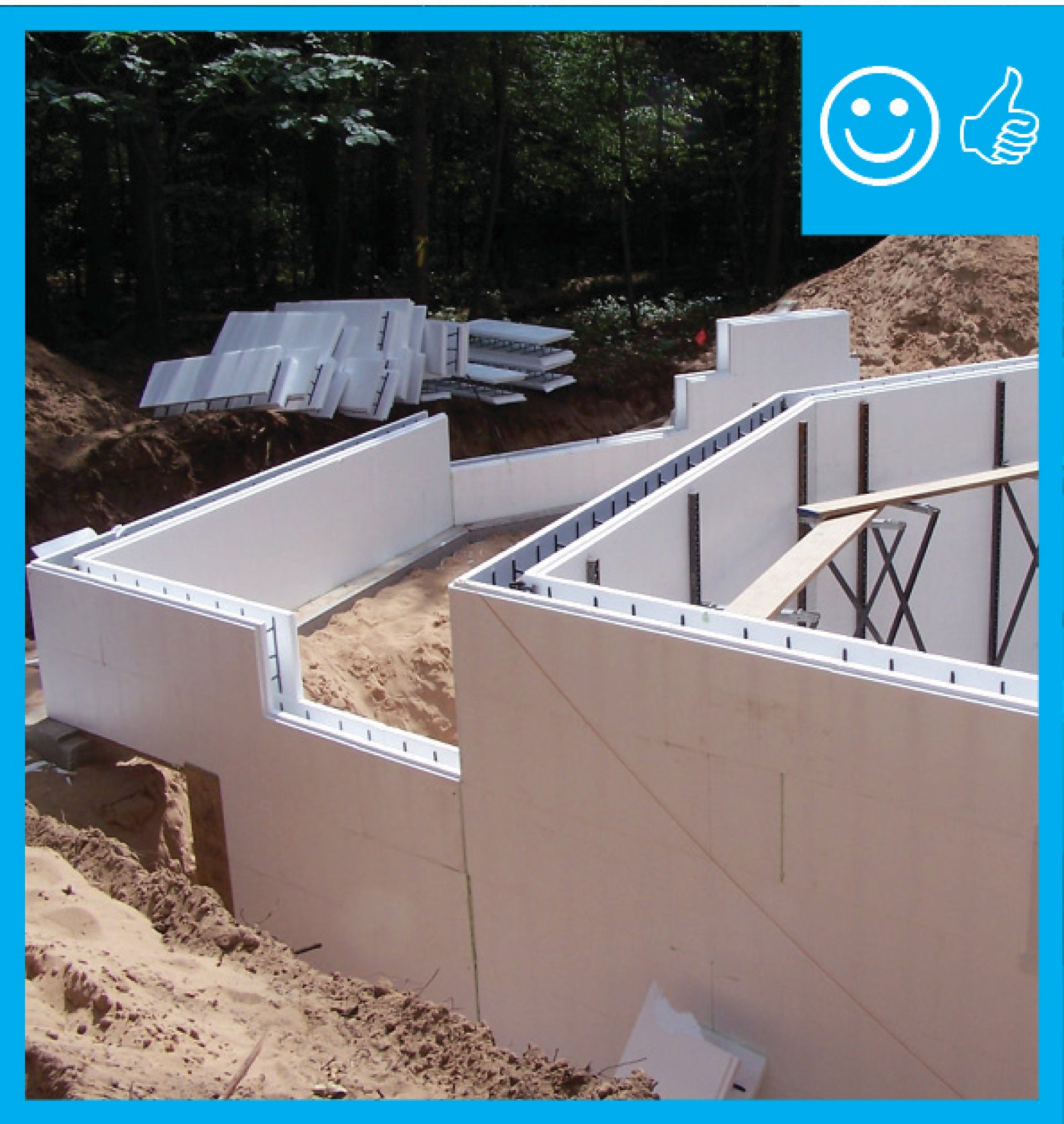
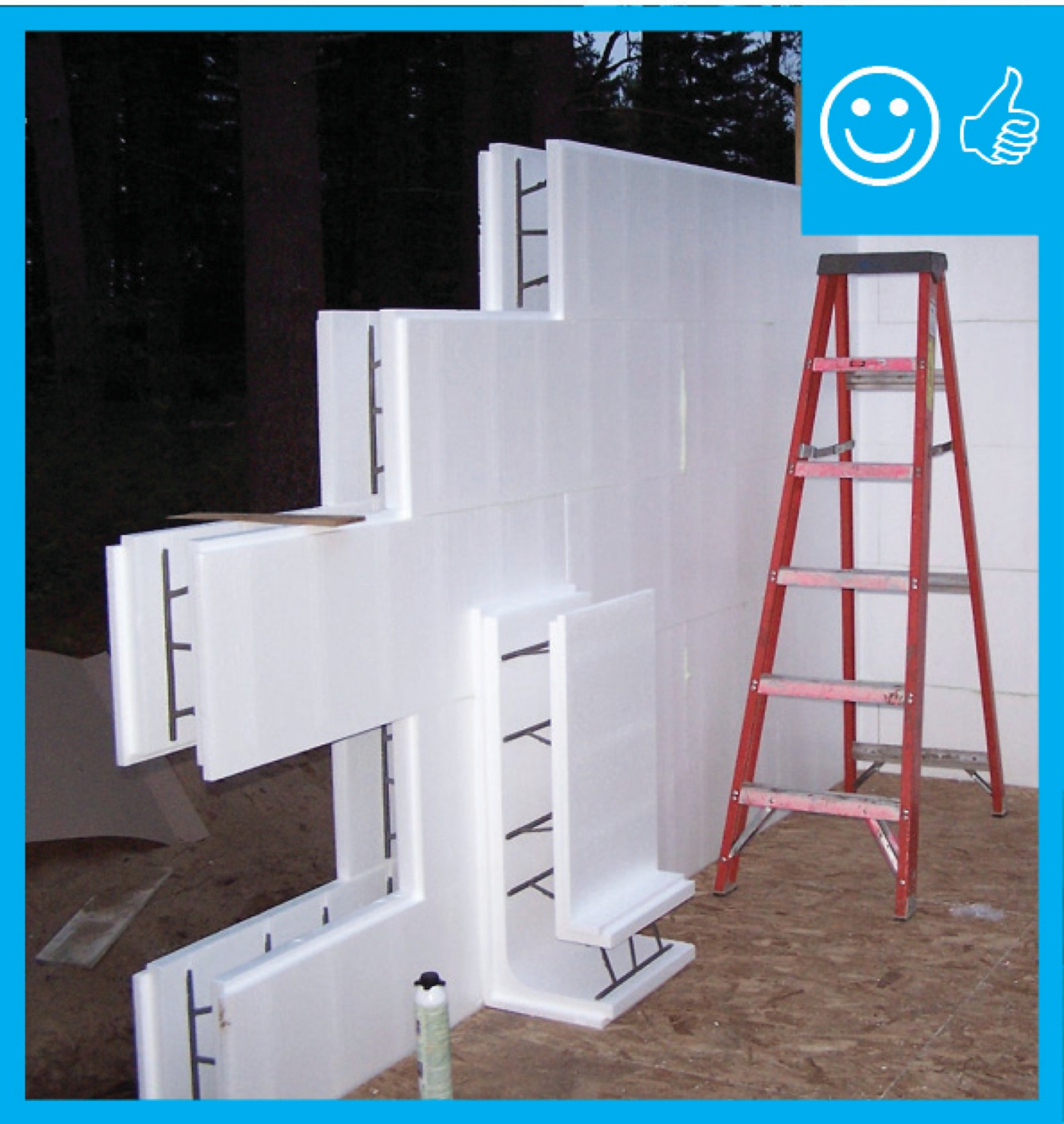
Right and Wrong Images
Source
Guide describing details that serve as a visual reference for each of the line items in the Thermal Enclosure System Rater Checklist.
Source
Guide describing details that serve as a visual reference for each of the line items in the Thermal Enclosure System Rater Checklist.

Source
Guide describing details that serve as a visual reference for each of the line items in the Thermal Enclosure System Rater Checklist.

Source
Guide describing details that serve as a visual reference for each of the line items in the Thermal Enclosure System Rater Checklist.
Source
Source
Source

Source
Source
Source
Guide describing details that serve as a visual reference for each of the line items in the Water Management System Builder Checklist.
Source
Guide describing details that serve as a visual reference for each of the line items in the Water Management System Builder Checklist.
Source
Source
Source

Source
Document describing good practices for insulating basements in new and existing homes.
Source
Source
Source
Source

Source
Source
Source
Source
Source
Source
Source
Source
Source
Source
Source
Source

Source
Source
Source
Source
Source
Source

Source
Videos

CAD Files
Compliance
More Info
Case Studies
References and Resources
*For non-dated media, such as websites, the date listed is the date accessed.
Contributors to this Guide
The following authors and organizations contributed to the content in this Guide.
Sales
Insulated Concrete Forms (ICFs) = ICF Thermal Blanket
Technical Description
Insulated concrete forms use hollow rigid foam insulation blocks that are stacked like bricks to form walls that are then reinforced with steel rebar and filled with poured concrete. These systems greatly reduce the amount of wood framing in exterior walls. The foam insulation creates a thermal blanket that reduces the heat transfer between the inside and the exterior. The reinforced concrete adds thermal mass for buffering excessive temperatures and provides additional resistance to strong winds, storms, and fire.
Questions? Comments? Contact our webmaster.