

Scope
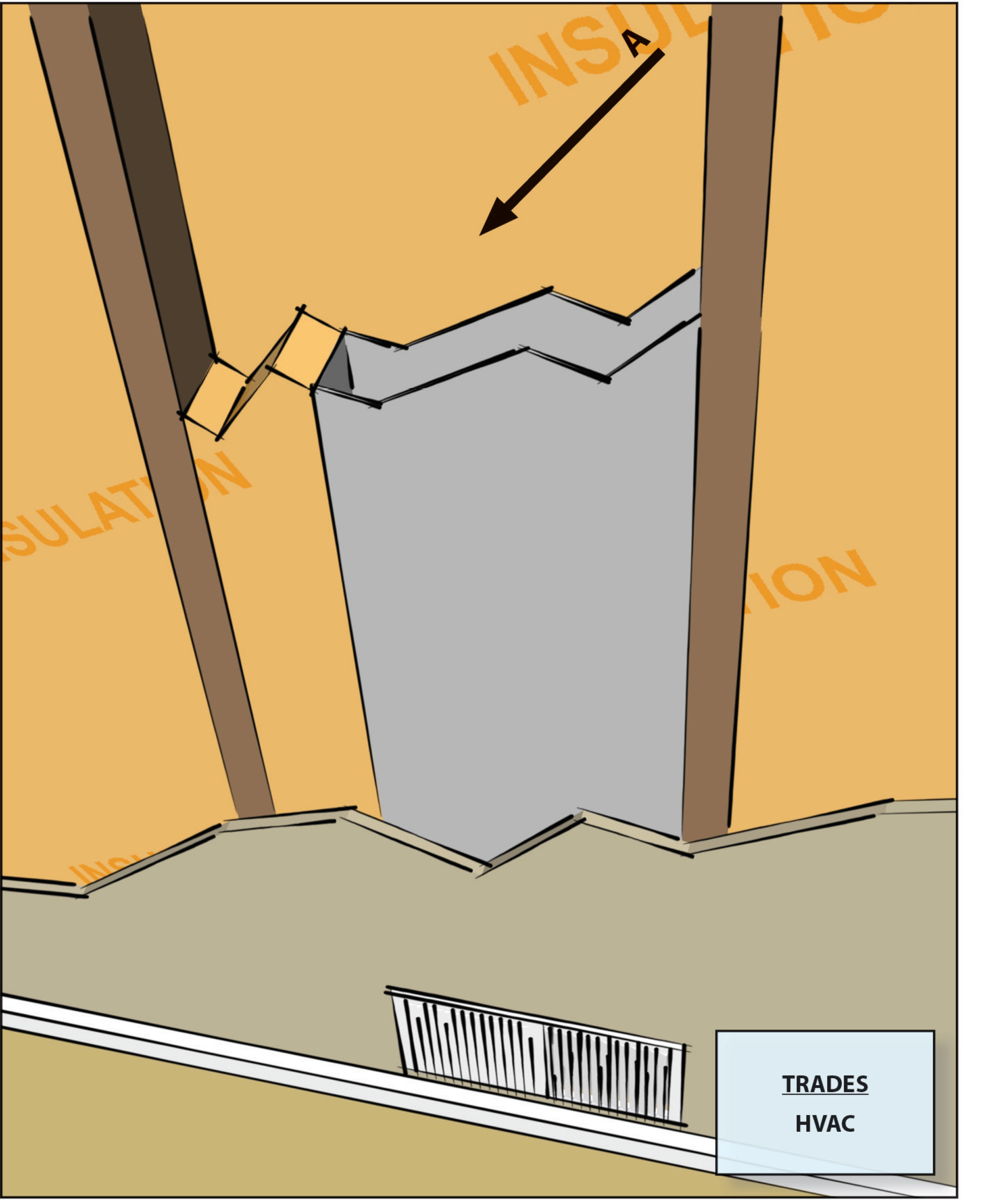
Do not install HVAC ducts in exterior walls.
If ducts must be run within exterior walls, at least R-6 continuous insulation should be provided on the exterior side of the cavity, along with an interior and exterior air barrier.
See the Compliance tab for links to related codes and standards and voluntary federal energy-efficiency program requirements.
Description
In the past, it was common practice to run ducts inside a wall cavity of an exterior frame wall. It is sometimes done today. However, we have learned that this practice will create an energy penalty and can cause durability issues within the wall cavity.
Ducts in exterior wall cavities experience unnecessary heat gain and loss through conduction, convection, and radiation, which creates an extra load on the HVAC equipment. Heat transfer through conduction takes place when the surface of the duct is in contact with the exterior sheathing. If there is an air space between the exterior sheathing and the duct, heat gain or loss will occur as air moves around the duct (convection). At the same time, the duct loses or gains heat from the exterior siding through radiant heat transfer.
Durability issues occur when humid air moves through cavity spaces which contain ducts that are carrying cool air because the humid air in the cavity space can condense on the exterior surfaces of the cool ducts. This scenario is a common occurrence in older homes in humid climates where cooling has been added to a forced air heating system that has ducts located in the exterior framed walls.
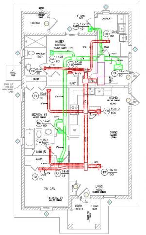
In older homes with poorly insulated walls and single-pane windows, supply registers are often located at or on exterior walls to condition the cold walls and cold air that would leak in at the windows. In new homes with better air sealing and insulation and higher performance double-pane windows, there is less heat transfer through exterior walls and less air leakage in and around windows. Exterior supply air throws are no longer necessary to maintain comfort; shorter duct runs with interior throws are preferred for improved energy efficiency and better HVAC performance. Duct layout should be considered at the design stage and the duct system should be designed for short, compact duct runs with interior throws and appropriately selected registers to achieve comfort across each room.
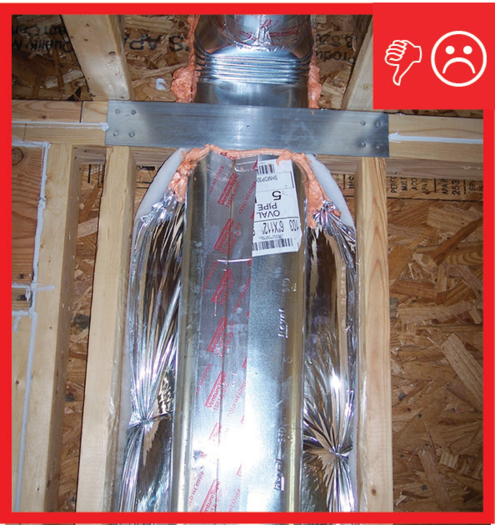
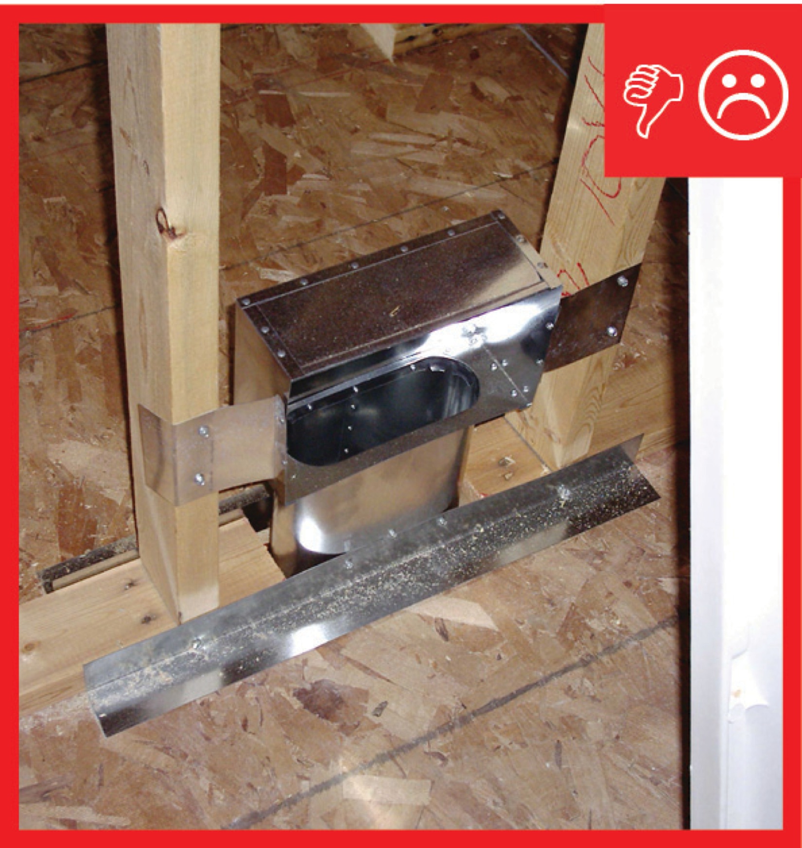
Another concern with ducts in exterior walls is adequate space. Standard wall cavities are not deep enough to house flex duct and may not be deep enough to house sheet metal duct, which should be wrapped in a minimum of 1 inch (R-4) of insulation. Rectangular fiber board duct might fit but analysis should be done to confirm that the space would accommodate the duct size required to meet the designed air flow per ACCA Manual D.
If ducts must be run in exterior wall cavity spaces, then R-6 rigid foam board insulation should be placed on the exterior side of the duct, between the exterior sheathing and the insulated duct. This rigid foam takes the place of the cavity insulation which is displaced by the duct and is in addition to any rigid foam used over or in place of the external wall sheathing. If ducts must run in exterior walls, make sure the interior and exterior air barrier are continuous and air tight.
How to Correctly Locate Ducts
Plan duct layout at the design stage. Design short, compact duct runs that do not run along exterior walls. Use floor or ceiling register locations. Be sure that the register box is air sealed to the floor or ceiling framing assembly. The register or grille should be removable so the register box can be cleaned periodically.
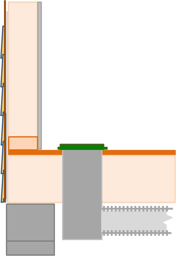
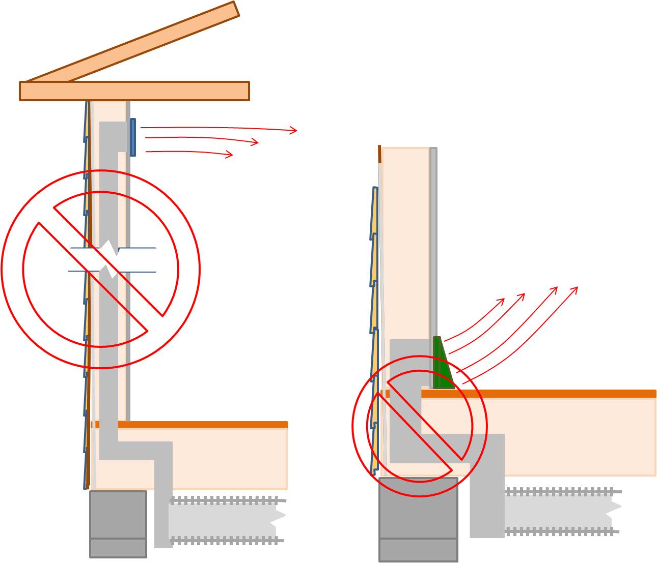
Figure 2 Or, if wall register locations are desired, run ducts in interior walls. Be sure the wall cavity space being used to house the ductwork is totally sealed from a vented attic or crawlspace.
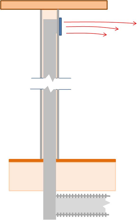
Figure 3 If ductwork must run inside an exterior wall cavity (not recommended), install continuous R-6 foam insulation board along the wall between the ductwork and the siding. Fill the cavity space around the duct with insulation. Ensure that a continuous air barrier exists along the interior and exterior of the exterior wall containing the duct by gluing exterior sheathing and drywall to framing, mudding and taping drywall seams, taping rigid foam sheathing seams, and caulking or foam air sealing around any wall penetrations.
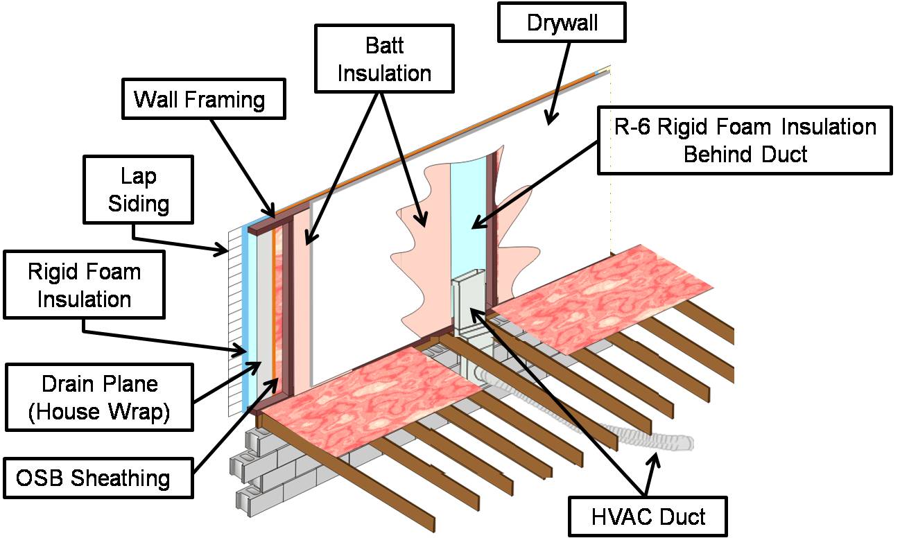
Figure 4
Ensuring Success
Inspect to ensure that ducts are not installed in exterior wall cavity spaces, if at all possible. The best way to ensure this is to design the duct layout early and to accommodate space for ducts in the framing layout, with short, straight duct runs and throws along interior walls and preferably with ducts and air handler located within the conditioned space. If ducts must be run in exterior wall cavity spaces, inspect to ensure that R-6 rigid foam board insulation is located between the exterior sheathing and the insulated duct. Also, if ducts must run in exterior walls, make sure the interior and exterior air barriers are continuous and air tight.
Region
No climate specific information applies.
Training
Right and Wrong Images
Source
Compliance
More Info
Case Studies
References and Resources
*For non-dated media, such as websites, the date listed is the date accessed.
Contributors to this Guide
The following authors and organizations contributed to the content in this Guide.
Sales
Proper Duct Installation = Professionally-Installed Comfort Delivery Ducts
Technical Description
Conditioned air is often lost in transition from comfort equipment to living spaces because of poorly designed duct layouts and poor installation practices, which cause homeowners to pay for conditioned air that never reaches the living spaces of their home. Poor duct layouts with overly long duct runs, numerous branches, and sharp bends, and poor installation with sagging, twisted, or crushed ducts, can severely limit air flow, reducing system performance and increasing energy costs. Professionally installed comfort delivery systems should be installed with compact duct layouts featuring short, straight duct runs with properly supported ducts, in accordance with industry standards. The ducts should be properly insulated, completely air sealed, and free from kinks and sharp bends that restrict air flow.
Questions? Comments? Contact our webmaster.