

Scope
Design and build walls to control condensation during cold weather events.
- In cold climates, use a Class 1 or 2 vapor retarder behind the drywall or use a Class 3 vapor retarder (e.g., latex paint on drywall) and warm the primary condensing surfaces within the wall assembly, typically the interior face of the sheathing by installing exterior continuous insulation in a sufficient ratio with the cavity insulation to prevent condensation on the interior face of the wall sheathing.
- Limit air leakage into the walls from conditioned space by ensuring a continuous air barrier and managing pressure differentials between the interior and exterior.
- Reduce indoor air humidity, which lowers the dewpoint, making condensation less likely.
- Use back ventilation of exterior cladding to help keep wall sheathing condensing surfaces dry.
See the Compliance Tab for links to related codes and standards and voluntary federal energy-efficiency program requirements.
Description
Condensation can occur in walls during cold weather if warm moist air from the house gets into the walls and water vapor in that warm air condenses on cold surfaces such as the inside surface of the wall sheathing.
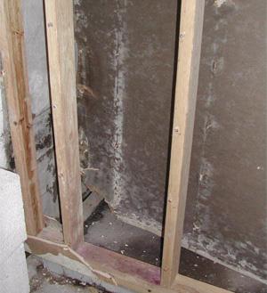
Wall assemblies should be designed and built to reduce and control condensation during cold weather. Condensation control includes reducing and limiting the potential for condensation, safely storing any condensation that does occur, and quickly drying out moisture when drying conditions return. Condensation control is important in order to avoid moisture-related wall issues such as mold growth, rot, corrosion, and delamination (Figure 1).
Source
Indoor airPLUS is a voluntary partnership and labeling program that helps new home builders improve the quality of indoor air by requiring construction practices and product specifications that minimize exposure to airborne pollutants and contaminants.
This guide will cover the following topics:
- conditions that cause condensation
- general approaches to limit condensation in walls
- wall construction and building operation techniques that follow these approaches
- condensation control issues related to wall retrofits.
Problems Caused by Condensation
Condensation in walls is an important concern to address for several reasons. While well-designed walls can handle low levels of moisture, elevated levels of moisture due to condensation can quickly lead to mold growth, which may pose a significant indoor air quality issue for building occupants. Repeated episodes or long periods of condensation can cause more serious structural damage due to rot and delamination of wood products such as OSB and plywood as well as corrosion and eventual failure of metal fasteners. These conditions can cause cladding attachment issues or more serious weakening of load-bearing components within the wall assembly.
Conditions that Cause Condensation
Condensation can occur on building materials when their surfaces drop below the dewpoint of the air they are exposed to. Cold conditions make condensation more likely by reducing the temperature of the outer portions of the wall below the dewpoint. During these cold conditions, condensation often occurs as frost (Straube 2011). Frost itself generally does not cause the issues discussed above. However, when warmer conditions arrive, the deposited moisture returns to a liquid state and this moisture must be safely stored by the material(s) until it can be dried. Therefore, wall assemblies built with materials that provide some safe moisture storage capacity are desirable, as are wall assemblies that are designed to assist drying.
During cold weather, the exterior air is generally very dry. However, air from the interior of the house is warm and often carries a much higher moisture load. If this interior air is allowed to enter a cold wall assembly, condensation is likely to occur. A pressure differential is needed to force interior air through holes in the air barrier into the wall assembly. Even the natural buoyancy of warm humid air within the building is enough to create this pressure differential. But greater pressure differentials caused by unbalanced mechanical ventilation, wind, or leaky ducts can exacerbate air leakage and therefore worsen condensation issues.
In summary condensation is caused by
- cold surfaces (below the dewpoint)
- a pressure differential and a hole in the air barrier, causing air leakage
- high humidity in warm indoor air
- lack of ventilation or drying potential.
General Approaches to Limit Condensation and its Effects
There are a number of effective approaches to limit condensation and/or to limit the damage caused by condensation. To limit condensation:
- Warm the primary condensing surfaces within the wall assembly, typically the interior face of the sheathing.
- Limit air leakage, especially of humid indoor air into the wall cavities. (This can be done by ensuring a continuous air barrier and managing pressure differentials between the interior and exterior.)
- Reduce indoor air humidity. This lowers the dewpoint, which makes condensation less likely, and reduces the amount of moisture that is deposited if condensation occurs.
- Use back ventilation of exterior cladding to help keep wall sheathing condensing surfaces dry.
To limit the impacts of condensation:
- Use materials in the wall assembly that can safely store water. These include solid wood, treated cellulose, and plywood. Try to avoid materials that are susceptible to moisture such as OSB and paper-faced gypsum. Also, be aware that many modern materials such as fiberglass, fiberglass-faced gypsum, and foams have little to no moisture storage capacity and can therefore concentrate moisture on more sensitive materials within the wall assembly.
- Increase the drying potential of the wall assembly by eliminating exterior vapor retarders, installing continuous exterior insulation and introducing back ventilation of exterior cladding to speed drying.
The Perfect Wall
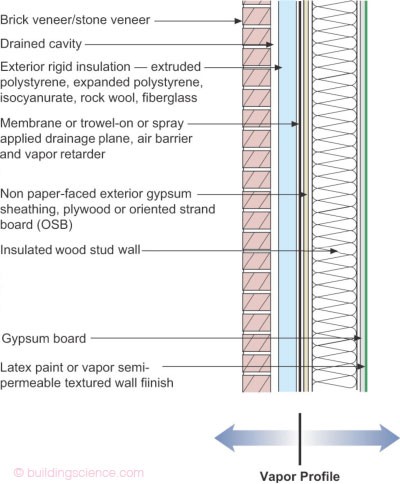
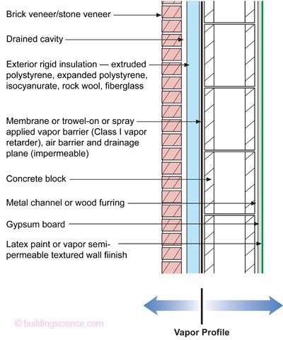
There is one wall type that controls condensation well in all conditions, including extreme cold. This is the “Perfect Wall.” See examples in Figures 2 and 3. Also see “The Perfect Wall ” by Lstiburek (2010) and “Flow-Through Assemblies” by Lstiburek (2016). Also see numerous examples of wall assemblies in Moisture Control for Residential Buildings by Lstiburek (2020).
Conceptually, the Perfect Wall combines all of the wall-design principles listed above into a single assembly, although it can be built in different ways using various materials. See Lstiburek 2017 “Hybrid Assemblies” for several wall configurations that manage condensation in different climates zones.
Source
Article discussing flow-through assemblies of walls.
Source
Article describing the perfect wall and and in what order to control rain, air, vapor, and heat.
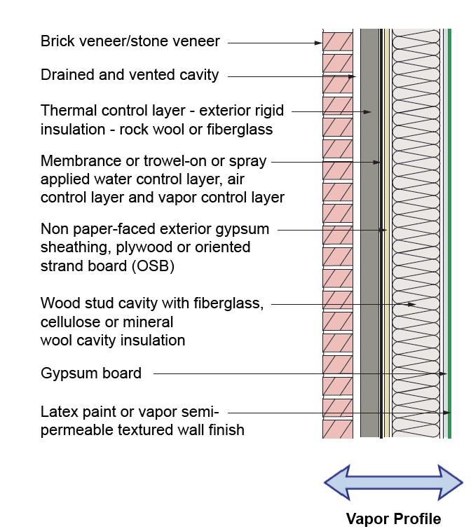
From inside to outside the Perfect Wall is composed of
- interior finish material (such as gypsum board)
- structure (such as studs and sheathing or concrete block)
- water, air, and vapor control layers (often combined into a single membrane)
- thermal control layer (such as rigid foam, fiberglass or mineral fiber board)
- vented air gap
- exterior cladding (fiber cement, vinyl siding, stucco, wood siding, etc).
By placing the insulation on the exterior side of the structure, moisture-sensitive condensing surfaces such as wood studs and sheathing are kept at room temperature year round, well above the dewpoint in even the coldest conditions. Sandwiched between the rigid insulation and the sheathing, the air barrier is protected from puncture. It is also uninterrupted by interior walls, floors, rim joists, and other intersecting members that can otherwise make installation of a continuous air barrier difficult. Finally, by introducing ventilation behind the cladding, the drying capacity of the wall assembly is increased, should any condensation or water leakage occur. When the perfect wall is combined with a well-designed and built mechanical system that manages indoor relative humidity and uses balanced ventilation with tightly sealed ducts (not framing cavities), condensation in wall assemblies can be eliminated in virtually all conditions.
Construction Techniques to Avoid Condensation
The likelihood of damaging condensation occurring in conventional wall assemblies can be reduced as well, by borrowing principles from the Perfect Wall construction.
Use exterior insulation to keep sheathing and/or other structural members and surfaces warm.
In general, there are two possible approaches:
- Thin layers of exterior insulation will help keep condensing surfaces such as the sheathing warmer, which reduces condensation potential and aids drying. However, since the sheathing will still frequently fall below the dewpoint in cold conditions, condensation may still occur. Thus, it is important to allow the wall to dry to the outside through the use of vapor-permeable exterior insulation.
- Thick layers of exterior insulation will keep the sheathing and other condensing surfaces warm throughout the winter. Using this approach, the structural layers of the wall are effectively part of the interior climate and can therefore dry to the inside. The exterior insulation may be vapor impermeable (such as rigid XPS foam, foil-faced foam, and closed-cell spray foam) and it becomes important not to restrict drying to the interior. In this case, weaker vapor retarders such as Class 3 or “smart” vapor retarders are desirable on the inside (warm in winter side) of the wall. Residential building codes provide guidance on how much exterior insulation should be used in combination with warm-side Class 3 vapor retarders.
Code does say in climate zones 5 and higher, that a Class 1 (poly sheeting) or Class 2 (kraft-facing) vapor retarder is required on the interior side of the wall; however, code permits use of a Class 3 vapor retarder (like latex paint) rather than Class 1 or 2 vapor retarders if rigid continuous insulation is installed exterior of the sheathing to control condensation in the wall (Lstiburek 2017 “They All Laughed”). (In Climate Zones 5 and Marine 4, back venting of the cladding is permitted in lieu of installing exterior continuous rigid insulation.) The ratio of exterior rigid continuous insulation to cavity insulation is important; as the climate zone gets colder, the amount of exterior continuous insulation has to increase as a percentage of overall wall R value to prevent condensation, as can be seen in Table 1 (adapted from Lstiburek 2017 Hybrid Assemblies, which is based on 2018 IRC Table R 702.7.1. See also the discussion in Lstiburek 2016 “Flow-Through Assemblies.”)
Also note that exterior rigid insulation may need to be greater than the minimum required by code in some climates zones to meet the ratio needed to avoid condensation issues when only a Class 3 vapor retarder is used. You don’t have to follow the ratios if you install a Class 1 (poly sheeting) or Class 2 (kraft-facing) vapor retarder over the cavity under the drywall. However, a Class 3 vapor retarder (like latex paint) provides a more forgiving wall, i.e., it has higher drying potential if it does get wet.
| Climate Zone | IRC Minimum R-Value* | Rigid Board or Air Impermeable Insulation | Total Cavity Insulation | Total Wall Assembly Insulation | Min. Ratio of Rigid Board Insulation or Air Impermeable R-Value to Total Insulation R-Value |
|---|---|---|---|---|---|
| 4C | 20 or 13+5 | R-2.5 | R-13 | R-15.5 | 15% |
| R-3.75 | R-20 | R-23.75 | |||
| 5 | 20 or 13+5 | R-5 | R-13 | R-18 | 30% |
| R-7.5 | R-20 | R-27.5 | |||
| 6 | 20+5 or 13+10 | R-7.5 | R-13 | R-20.5 | 35% |
| R-11.25 | R-20 | R-31.25 | |||
| 7 | 20+5 or 13+10 | R-11.25 | R-13 | R-24.25 | 45% |
| R-15 | R-20 | R-35 | |||
| 8 | 20+5 or 13+10 | R-15 | R-13 | R-28 | 50% |
| R-20 | R-20 | R-40 | |||
| * The first value is cavity insulation, the second value is continuous insulation. For example, “13+5” refers to R-13 cavity insulation plus R-5 continuous insulation. | |||||
Ensure the air barrier is complete and well-sealed.
Polyethylene installed as an air barrier directly beneath drywall is particularly susceptible to punctures and hard to seal due to frequent interruptions. An exterior-side air barrier is much easier to install in a continuous fashion and easier to inspect for continuity as well. However, if an exterior air barrier is used, air flow can still occur within the wall and framing cavities due to pressure differentials or natural convection. These air flow paths may bring humid indoor air into contact with cold condensing surfaces within the wall cavity even if the air is not escaping the building. Limit air flow within wall cavities by using dense-pack fibrous insulation (not batts) when an exterior air barrier is used.
Taped, mudded drywall, with all penetrations air sealed and airtight drywall installation with foam tape gaskets or caulk or fluid-sealants at drywall-to-framing seams and at wood-to-wood framing joints including at top plates and bottom plates are among the methods for creating an air barrier on the interior of the wall assembly. Interior vapor retarders may be needed if the wall assembly does not include back-ventilated cladding. There are many articles and Solution Center guides that describe best practices for air barrier installation.
The following articles provide information on understanding vapor control and air barriers in homes:
- Controlling Cold-Weather Condensation Using Insulation, BSD-163
- Critical Seal (Spray Foam at Rim Joist), Info-408
- Five Things, BSI-039
- Joni Mitchell, Water and Walls, BSI-071
- Just Right and Airtight, BSI-053
- Moisture Control for New Residential Buildings, BSD-012
- Moisture Control Guidance for Building Design, Construction and Maintenance
- Moisture Control in Buildings: Putting Building Science in Green Building
- Sealing Air Barrier Penetrations, Info-405
- The Perfect Wall, BSI-001
- They All Laughed, BSI-026
- Understanding Air Barriers, BSD-104
The Building America Solution Center has several guides on specific air sealing techniques to establish an air barrier within the wall assembly:
- Air Seal Top Plates or Blocking Missing at Top of Walls Adjoining Unconditioned Spaces
- Air Sealing Drywall to Top Plate
- Air Sealing Sill Plates
- Air Sealing Plumbing and Piping
- Building Cavities Not Used as Supply or Return Ducts
- Building Science Introduction – Air Flow
- Continuous Air Barrier in Exterior Walls
- Rigid Foam Insulation for Existing Exterior Walls
- Walls Behind Fireplaces
- Walls Behind Showers and Tubs
Manage pressure differences between indoor and outdoor air.
Although it’s not feasible to entirely eliminate pressure differences, there are a number of important strategies that can minimize them and reduce the amount of indoor air driven into wall cavities. These strategies include the following:
- Use balanced ventilation (such as an HRV or ERV-based system) and minimize exhaust or supply-only fans.
- Use well-sealed ducts rather than framing cavities to move conditioned air around the building.
- Place ducts and HVAC equipment in conditioned space within the air barrier.
- Install sealed-combustion or electric appliances.
- Provide dedicated make-up air for exhaust devices such as clothes dryers and kitchen range hoods.
Ensure adequate indoor ventilation.
As new buildings become more airtight, humidity from daily activities such as showering and cooking can build up inside the building. The need for balanced mechanical ventilation to keep relative humidity at an acceptable level during the heating season increases. Most sources recommend an indoor relative humidity between 30% and 50% during the heating season.
Use building materials that provide safe moisture storage when possible.
Solid wood, treated cellulose, treated fiberboard, and plywood have safe moisture storage capacity. Many wood products made from chipped or ground wood (OSB, MDF, and the paper facing on gypsum board) are more easily damaged by moisture and provide more readily available nutrients for mold growth. Plastics, foams, and fiberglass have little to no storage capacity and tend to concentrate water on sensitive materials in the wall assembly.
Incorporate back-ventilated cladding.
Vinyl siding and cladding installed over furring strips or drainage mats provide pathways for exterior air to dry out wet sheathing, exterior insulation, and the cladding itself.
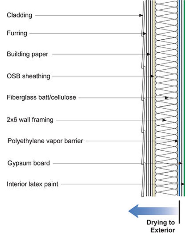
Maintain open drying pathways by avoiding double vapor retarders (“vapor sandwiches”) that can trap moisture.
From a vapor standpoint, the wall needs to be able to dry to the inside (Figure 2), the outside (Figure 4), or in both directions (Figure 5). Always be aware of the wall’s intended drying pathway and natural drying direction for the climate. In cold climates, walls tend to be designed to dry outward; in warm climates inward. In mixed climates, drying can be bi-directional. Double vapor retarders occur when vapor-impermeable cladding, interior finish materials, insulation products, or membranes are installed in addition to a vapor retarder, without consideration for the intended drying pathway.
Source
Article describing the evolution of the IRC to permit class 3 vapor retarders (latex paint) in walls coupled with exterior continuous insulation to allow drying and reduce condensation risk.
Source
Report providing extensive guidance on controlling moisture in building envelopes through proper selection and installation on air, water, thermal, and vapor barriers.
Ensuring Success
An important aspect of controlling condensation during cold conditions is limiting the leakage of warm, humid, indoor air into wall assemblies and framing cavities. Eliminating all pressure differentials and cold surfaces within the wall assembly will be difficult during extreme conditions, but these factors matter far less if the air barrier is robust and continuous. Inspect the air barrier for continuity and check its performance with a blower door test. Identify any sources of air leakage and seal those before installing finish materials. Unlike vapor retarders, multiple air barriers can be employed in a “belt and suspenders” type approach to help ensure success, as long as each air barrier is continuous.
If condensation does occur, it is imperative that moisture can dry quickly. To aid drying, ensure the wall has an open drying pathway by avoiding double vapor retarders and introducing back-ventilated cladding.
Another approach is to use a Class 3 vapor retarder on the drywall and install enough exterior continuous insulation, relative to cavity insulation following the ratios shown in Table 1 on the Description tab, to keep the wall sheathing sufficiently warm to control condensation.
Typical R-values for common insulation materials are summarized in this table, which also identifies the vapor retarder classification for each insulation.
Region
The map in Figure 1 shows the climate zones for states that have adopted energy codes equivalent to the International Energy Conservation Code (IECC) 2009, 12, 15, and 18. The map in Figure 2 shows the climate zones for states that have adopted energy codes equivalent to the IECC 2021. Climate zone-specific requirements specified in the IECC are shown in the Compliance Tab of this guide.

Source
2012 edition of code establishing a baseline for energy efficiency by setting performance standards for the building envelope (defined as the boundary that separates heated/cooled air from unconditioned, outside air), mechanical systems, lighting systems and service water heating systems in homes and commercial businesses.

Source
2021 edition of code establishing a baseline for energy efficiency by setting performance standards for the building envelope (defined as the boundary that separates heated/cooled air from unconditioned, outside air), mechanical systems, lighting systems and service water heating systems in homes and commercial businesses.
Cold Climates
In very cold climates (see maps), multiple surfaces within a wall assembly will be below the dewpoint for much of the heating season. In these climates, a continuous air barrier inboard of those cold surfaces is the best defense against condensation. But drying pathways must be established as well in case condensation or other moisture issues arise. Drying pathways are primarily determined by the placement of vapor retarders and insulation. Historically, a strong warm-side vapor retarder (Class 1 or Class 2) has been used as described in the Description/shown in Figure 4 (see also Lstiburek 2017 “They All Laughed”). However, that assumes the wall can dry to the outside. If impermeable exterior insulation is used, sheathing and structural members will need to dry to the inside and a weaker warm-side vapor retarder (Class 1) should be used (see Figures 2, 3, and 5). The ratios of exterior to cavity insulation to minimize risk of condensations are discussed on the Description tab. If the exterior continuous insulation is vapor open, the wall can dry to either side.
Mixed Climates
In mixed climates, condensation is less likely to occur, but can be an issue during extreme winter weather events. Considerations for the vapor retarder placement and drying pathways change. In mixed climates, walls are generally designed to dry in both directions depending on the season (outward in winter, inward in summer). Therefore, a strong vapor retarder should be avoided as it may impede one of these drying directions. A Class 3 vapor retarder is permitted by code in Climate Zones 4C and 5 if either exterior insulation is used or the wall cladding is back vented with an air gap of at least 1/32nd inch (a draining house wrap, cap nails, or washers will suffice; see Lstiburek 2017, “They All Laughed”).
Training
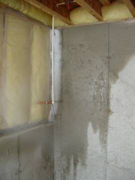
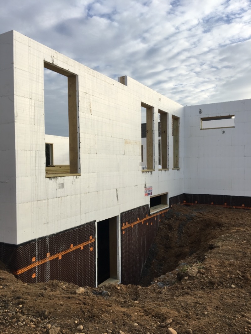
Right and Wrong Images
Source
Article discussing flow-through assemblies of walls.
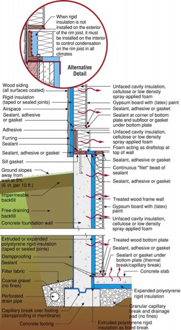
Source
Document describing good practices for insulating basements in new and existing homes.
Source
Article describing the evolution of the IRC to permit class 3 vapor retarders (latex paint) in walls coupled with exterior continuous insulation to allow drying and reduce condensation risk.
Source
Source
Videos


Compliance
Retrofit
For retrofits, general approaches and construction techniques to limit condensation remain the same. However, keep in mind that some common wall retrofit practices can make condensation issues worse. These are identified below.
- Adding cavity insulation to an existing wall will reduce heat loss but also reduce the drying potential of the wall. Many existing walls rely on that heat flow to drive off excess moisture from condensation, water leakage, or other sources. Therefore, cavity insulation can lead to wetter walls unless steps are taken to air seal them at the same time. Air sealing will reduce the amount of moisture inside wall cavities and help maintain a balance between wetting potential and drying potential as insulation levels are increased.
- Keep in mind that air sealing retrofits can lead to more humid indoor air. To counteract this, increased ventilation (preferably with heat recovery in cold climates) should be combined with air sealing efforts to maintain adequate ventilation rates and reasonable indoor relative humidity levels.
- In cold climates, most wall types dry to the outside. To maintain this critical drying pathway, avoid using vapor-closed products on the exterior side of the wall, which can create a cold-side vapor retarder. Examples of vapor closed products include low-perm peel and stick membranes, XPS foam, foil-faced products, and some types of insulated siding installed without back-ventilation.
- Consult the Building America Solution Center guide “Pre-Retrofit Assessment of Walls, Windows, and Doors” before beginning a wall retrofit. This guide covers important inspections and common issues for older walls that should be addressed before retrofits can be carried out successfully.
More Info
References and Resources
*For non-dated media, such as websites, the date listed is the date accessed.
Questions? Comments? Contact our webmaster.