

Scope
Choose the highest performing cooling equipment that project funding will allow, to meet the cooling load of the project. Consider a heat pump instead of an air conditioner. A heat pump is basically an air conditioner with a reversing valve so that it can switch between air conditioning and heating. With rebates a heat pump can cost less to purchase than an air conditioner.
If the design cooling load is low (below around 14,000 Btuh capacity) due to high insulation and air sealing levels or a mild climate, consider equipment that can modulate (vary the refrigerant flow) such as a ducted or ductless inverter-driven heat pump. In dry climates, consider direct/indirect evaporative coolers and ventilation cooling. Also consider passive cooling techniques such as shading with architectural and landscape features. See the Passive and Low-Energy Cooling guide for more information.
Confirm that the selected system is a matched system, as certified according to the Air-Conditioning, Heating, & Refrigeration Institute. AHRI assigns a certification number and efficiency ratings to specific combinations of equipment (outdoor unit, indoor unit, indoor coil, fan type, etc.) that have been tested by the manufacturer according to AHRI test procedures using AHRI-specified test conditions (AHRI 2012).
Install in accordance with the manufacturers’ instructions and relevant standards including ACCA Standard 5: HVAC Quality Installation Specification, ACCA’s Technician's Guide for Quality Installations, and ACCA Standard 9: HVAC Quality Installation Verification Protocols. Consider using tools such as the Quality Install Tool to document.
Properly select the cooling equipment and duct sizes for the design cooling load of the home, following the sizing guidelines in ACCA’s Manual S: Residential Equipment Selection. When determining equipment sizing per ACCA Manual S, use the original equipment manufacturer (OEM)’s expanded performance table to obtain performance data at design conditions, rather than using the performance data on the AHRI certificate, which lists heating and cooling capacity and SEER2 and EER2 cooling efficiencies at factory conditions of 95°F outdoor, 80°F indoor, and 67°F wet bulb.
The OEM-listed capacity at design conditions should be between 95% and 115% of the design total heating load calculated in the Manual J HVAC load calculation, or the next nominal size. The next largest nominal piece of equipment available may be used to satisfy the latent and sensible requirements. Most equipment manufacturers sell nominal sizes in increments of one-half ton.
If the whole-house ventilation system uses the air conditioner air handler fan, then the fan motor should be a variable speed electronically commutated motor (ECM) or an integral control motor (ICM) that includes a controller (e.g., a smart cycler) that reduces the ventilation run time by accounting for hours when the HVAC system is already operating the fan for heating or cooling the home.
Design an efficient air distribution system with a compact layout in accord with ACCA Manual D. Install ducts properly for maximum airflow and efficiency. Consider zoning for low-load homes (over 1,000 sq ft per ton of cooling) with thermostat-controlled dampers.
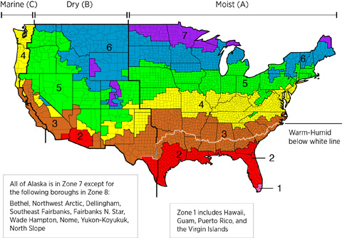
If you are participating in an energy-efficiency program, select cooling equipment that complies with the requirements for your climate zone. To determine your climate zone, see the International Energy Conservation Code (IECC) climate zone map on the Climate tab.
See the Compliance Tab for links to related codes and standards and voluntary federal energy-efficiency program requirements.
Description
Vapor-compression refrigeration (compression cooling) systems are the most common type of cooling equipment used to cool residential and commercial buildings. Compression cooling is often referred to as air conditioning, although technically any system used to intentionally heat, cool, or ventilate the indoor air could be referred to as an air conditioning system. Residential compression cooling systems include any system that uses the refrigeration cycle for space cooling; this includes split-system air conditioners, unitary air conditioners, air-source heat pumps, and ground-source (or geothermal) heat pumps, in system sizes up to 65,000 Btuh with forced-air distribution systems. Noncompression cooling systems include evaporative cooling and absorption systems. However, the lion's share of the U.S. housing market utilizes a compression cooling system for space cooling. According to data from the U.S. Energy Information Administration (data collected in 2009 and released in 2013), 94 million out of 113.6 million households had some kind of cooling equipment – 69.7 million of those homes had central compression-based air conditioners (19% of these were heat pumps), 25.9 million had window or wall-unit air conditioners, and 2.8 million had an evaporative or swamp cooler (EIA 2013). Other cooling options available to consumers that are worth considering because of their energy-saving potential include passive cooling techniques such as shading with architectural and landscape features, night ventilation cooling systems, and ceiling fans. See the Passive and Low-Energy Cooling guide.
The compression cooling cycle, especially as it applies to split-system central air conditioners, is described here. Traditional split heat pumps, mini-split heat pumps, and ground-source heat pumps are described in more detail in other guides, as are evaporative cooling systems and absorption cooling.
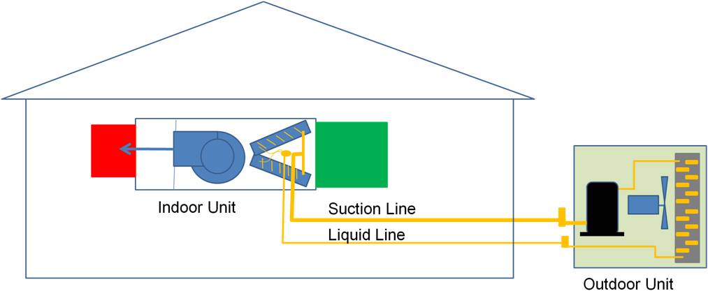
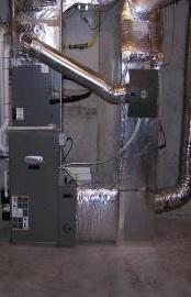
Central air conditioners are typically installed with central furnaces and use the same blower and duct distribution system. Residential air conditioners are typically split systems, which refers to the fact that there is an outside unit and an inside unit: the condenser and compressor are part of an outside unit, and the evaporator and expansion valve are located within the air handler in the inside unit (Figure 1). Refrigerant is piped to the evaporator coil in the air handler unit where it cools the distribution air.
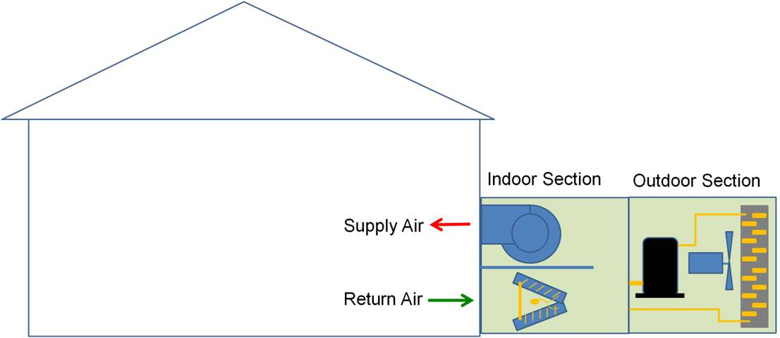
Window- or wall-mounted room air conditioners contain all of the components in one box. Larger single-unit air conditioners called packaged-unit air conditioners also contain all of the components (the compressor, condenser, evaporator, expansion device, and blower fan) in one unit that is located outside, typically mounted on the wall or on the roof (Figure 2). The conditioned air is vented inside either directly into a room or into a duct system for distribution throughout the building. Many small commercial buildings are equipped with packaged units but they are rarely used for single-family homes.
Packaged air conditioners and heat pumps come from the factory ready to go as soon as they are connected to a duct system, thermostat, and power source. Split systems have to be plumbed, i.e., the indoor unit must be connected to the outdoor unit via refrigerant piping, and electrical wiring must be connected to both units.
Air Conditioner Capacity and Sizing
Air conditioners are sized by their capacity in terms of tons. One ton equals 12,000 Btu/hour of cooling capacity. The capacity is often indicated in the model number. Look at the name plate on the outdoor condensing unit and locate the model number (not the serial number). Look for two digits in the model number that match the numbers below to indicate tons or Btus/hour. For example, a model SSX160241 is a 2-ton (24,000 Btu/hr) air conditioner.
18 = 1.5 Ton (18,000 Btu/hr)
24 = 2 Ton (24,000 Btu/hr)
30 = 2.5 Ton (30,000 Btu/hr)
36 = 3 Ton (36,000 Btu/hr)
42 = 3.5 Ton (42,000 Btu/hr)
48 = 4 Ton (48,000 Btu/hr)
60 = 5 Ton (60,000 Btu/hr).
Proper sizing of air conditioners has become more important in recent decades as homes have become more air-tight and better insulated. HVAC contractors can no longer rely on rules of thumb based on a rough estimate of square footage. Where an older two-story 3,000-ft2 home might have required two 3-ton units, a new 3,000-ft2 high-performance home might be adequately served by one 3-ton unit with zone dampers.
An oversized system will turn on and bring the air temperature down below the thermostat set point quickly then shut off before the system has had time to remove moisture from the air, which can cause high humidity problems in the home, especially in humid climates. The HVAC contractor should use ACCA’s Manual J: Residential Load Calculation to calculate the home’s cooling load and ACCA’s Manual S: Residential Equipment Selection to correctly size the central air conditioning system. ACCA makes available Excel-based spreadsheets to help contractors with these calculations.
The HVAC equipment that is installed must be a matched system, as certified according to the Air-Conditioning, Heating, & Refrigeration Institute (AHRI). AHRI is an industry association that assigns a certification number and efficiency ratings to specific combinations of equipment (outdoor unit, indoor unit, indoor coil, fan type, etc.), which have been tested by the manufacturer according to AHRI test procedures using AHRI-specified test conditions (AHRI 2012). See the AHRI Directory of Certified Products. Proper matching of system components according to AHRI is important for equipment warranty and one of the items that will be confirmed by a rater if the home gets an energy assessment such as a Home ENERGY Rating System (HERS) score.
Many designers use the performance data listed on the AHRI certificate for selecting equipment to meet the home’s design cooling load. However, a more accurate method (and one required by ACCA Manual S) is to use the original equipment manufacturer (OEM's) expanded performance table to obtain performance data at design conditions. AHRI uses a specific set of conditions (95°F outdoor, 80°F indoor, and 67°F wet bulb) when determining the equipment performance data, such as heating and cooling capacity and SEER2 and EER2 cooling efficiencies; these performance data are then listed on the AHRI certificate. The OEM expanded performance tables list data for many more cooling conditions. An example expanded performance table is shown below for a 1.5-ton air conditioner. Linear interpolation can be used to find the performance data for conditions in between two data points.

With a central air conditioning system, the cooled air will be distributed by ducts so it is important to design an efficient air distribution system with a compact layout in accord with ACCA Manual D. Good installation (with short straight runs and air-sealed and insulated ducts) is important for maximum airflow and efficiency. Consider the the ENERGY STAR Single-Family New Homes Checklist for prescriptive requirements for duct installation quality targets. For best performance, the ducts and air handler should be located within the home’s thermal boundary (this is a DOE Zero Energy Ready Home requirement).
Some new homes are so well air sealed and insulated, they can be considered low-load homes (over 1,000 square feet of floor space per each ton of cooling). While older, less air-tight, less well air sealed homes might require two or more cooling units or one large unit, for example a 5-ton unit, with well-insulated homes, one smaller unit, perhaps 2 or 2.5 tons, might do.
For larger homes with one unit, zone dampers are recommended. The dampers are located near the air handler unit at the base of each branch duct that will serve a zone. The dampers communicate electronically with a computer that communicates with thermostats located in each zone. Dampers are a good idea for several reasons. They save energy because different temperatures can be set for different zones, and cooling can be reduced to less-used areas of the home. They also help provide more airflow where needed. Systems with intelligent blower fans can also slow the fan down when one or more zone dampers are closed.
The HVAC system sizing should be based on the heating or the cooling system, whichever is more in demand in your climate zone. Both the DOE Zero Energy Home Program and ENERGY STAR will allow designers to oversize furnaces by up to 150% to satisfy the airflow requirements of the cooling system. Cooling systems should not be oversized.
The Refrigerant Cycle
The vapor-compression refrigeration system uses a circulating liquid refrigerant as the medium that absorbs heat from the indoor air and rejects the heat outside. Figure 4 shows the path of the refrigerant as it cycles through a typical, single-stage vapor-compression air conditioner’s indoor and outdoor components. This figure depicts an air conditioner only. If this unit were part of a furnace, the system would have the blower pulling air from the return and blowing the air across the furnace’s gas heat exchanger then the air conditioner’s evaporator coil.
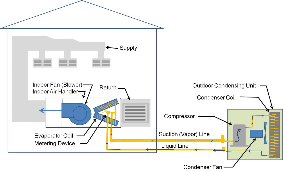
All compression cooling systems have four main components: a compressor, a condenser, a metering device (known as a thermal expansion valve (TXV), fixed orifice, or electronic expansion valve (EEV)), and an evaporator coil. Circulating refrigerant moves through the suction line and enters the compressor as a low-pressure vapor. In the compressor, it is compressed to a higher pressure and therefore a higher temperature. The now “superheated” vapor is routed through the condenser coil where it is cooled by flowing outdoor air. As a result, it condenses back into a liquid, releasing heat which is carried away by the flowing air.
The liquid refrigerant is carried back to the indoor unit where it passes through an expansion valve. The expansion valve (or metering device) causes the liquid refrigerant to experience an abrupt drop in pressure and temperature as it enters the evaporator coil. In the coil, the liquid absorbs heat from the circulating house air, thus cooling the house air that is passing through the air handler. The absorbed heat causes the refrigerant to turn to a low-pressure vapor again and the vapor is again routed outside to the compressor, beginning the cycle all over again.
Measuring the Efficiency of Cooling Systems
The efficiency of compression cooling systems is measured in SEER2, EER2, and COP.
Seasonal Energy Efficiency Ratio (SEER2) – the SEER rating of a unit is the cooling output during a typical cooling-season divided by the total electric energy input during the same period. The higher the unit's SEER2 rating the more energy efficient it is. In the United States, the SEER2 is the ratio of cooling in British thermal units (BTU) per hour to the energy consumed in watt-hours.
Energy Efficiency Ratio (EER2) – the EER2 of a particular cooling device is the ratio of output cooling (in Btu/h) to input electrical power (in watts) at a given operating point.
Coefficient of Performance (COP) - the COP (sometimes referred to as CP) of a heat pump is the ratio of the heating or cooling provided over the electrical energy consumed. The COP provides a measure of performance for heat pumps that is analogous to thermal efficiency for power cycles.
Technology improvements in recent years have made air conditioners much more efficient. These improvements include variable-speed fan motors, variable-speed compressors, electronic expansion valves, and micro-channel heat exchangers. These changes enable the air conditioner to vary the amount of refrigerant flow and thus modulate up or down rather than just turning on or off like a single-speed system would. By better matching the system’s cooling capacity to the cooling load, the newer models can improve efficiency, lower energy consumption, and increase comfort.
Since 2023, the federal government has required new air conditioners sold in the United States to have a SEER2 rating of 13.4 or higher when installed in the northern region. In the southeast and southwest regions, air conditioners must have a SEER2 rating of 14.3 for systems smaller than 45,000 BTUH and 13.8 for systems larger than or equal to 45,000 BTUH (SEER2 Guide).
To receive an ENERGY STAR label under Version 6.0, a split system air conditioner must have a SEER2 of 15.3 or greater. The best available central air conditioning units can have SEER ratings of well over 20.
Installation Concerns
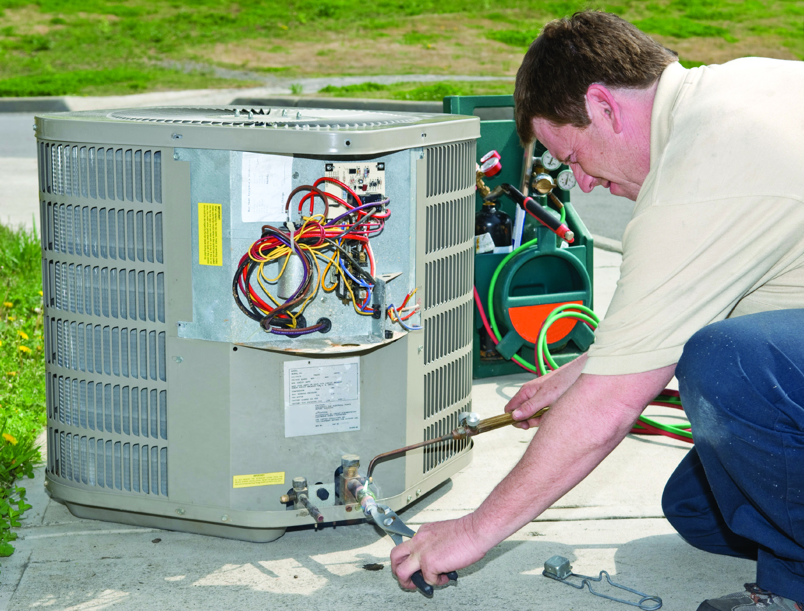
How the installation and connection of the copper tubing for the refrigerant lines is performed is critical to the life expectancy of the compressor. During new construction, the copper tubing is roughed in early on, before or during duct installation. The equipment (indoor unit and outdoor unit) is typically installed and connected to the copper tubing toward the end of construction. This means the copper lines can lay unconnected for quite some time.
Copper tubing used for refrigerant lines is sold in rolls (15-, 25-, 30-, and 50-foot lengths are common). The tubing is dried out (dehydrated) and sealed at both ends before shipping. Water is the enemy of the refrigeration system. If water vapor is allowed to enter the refrigeration lines during construction, it will greatly reduce the life of the compressor and create havoc with metering devices and check valves. The oil used for lubricant in refrigeration systems is highly hygroscopic, which means that the oil wants to absorb moisture. If the lubricant mixes with water or water vapor, it creates an acidic sludge that eats away at compressor windings, causing burnouts; the sludge can also block orifices and valve openings inside the system.
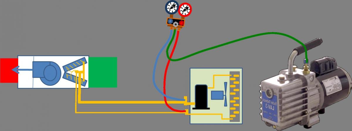
During the rough-in installation, the open ends of the copper tubing should be kept sealed at all times. When the installation is completed, the lines should be charged with dry nitrogen and soldered closed. After connecting the indoor unit and the outdoor unit, the lines should be vacuumed to 500 microns to remove moisture and non-condensable gases, which can reduce heat transfer and cause erratic operation (Figure 5).
Proper refrigerant charging is critical for maximizing the performance of compression cooling equipment. Too much or too little refrigerant can reduce the efficiency of the equipment and lead to premature component failures. Use the charging method recommended by the manufacturer. There are three methods for refrigerant charging: the subcooling method (typically for units with a thermal expansion valve), the superheat method (typically for units with a fixed orifice), or the weigh-in method (using the refrigerant weight amount listed on the data plate on the outdoor unit). Verify that you are using the correct method for the specific air conditioning model to be installed. Refrigerant charging must be done by an EPA-certified technician.
How to Select and Install Compression Cooling Equipment
- Choose the highest performing air conditioner that project costs will allow, in order to meet the design cooling load of the project. Consider variable-speed equipment that can modulate its output down to achieve comfort and energy efficiency during mild days that only require only a fraction of the cooling capacity of the design temperature condition. Variable-speed equipment is especially important if the design load is low (e.g., <14,000 Btu). In dry climates, consider direct/indirect evaporative coolers and ventilation or passive cooling. If you are participating in an energy-efficiency program, select cooling equipment that complies with the requirements for your climate zone, as described in the Compliance tab.
- Confirm that the selected system is a matched system, as certified according to the Air-Conditioning, Heating, & Refrigeration Institute (AHRI).
- Properly size the cooling equipment for the design cooling load of the home. Use ACCA Manual J to calculate your cooling load and use ACCA Manual S to correctly size your system. This is especially important if you have done significant air sealing and insulating, which will reduce your heating and cooling load.
- Design an efficient air distribution system with a compact layout in accord with ACCA Manual D. Install ducts properly for maximum airflow and efficiency in accord with ACCA Manual D. See also the Building America Solution Center guides on duct installation, insulation, and air sealing in the ENERGY STAR Single-Family New Homes Checklist.
- Charge the copper tubing with dry nitrogen, seal the open ends with solder, and keep the tubing sealed at all times during the rough-in installation to prevent moisture from entering the lines.
- Install in accordance with the manufacturers’ instructions and relevant standards including ACCA Standard 5: HVAC Quality Installation Specification, ACCA’s Technician's Guide for Quality Installations and ACCA Standard 9: HVAC Quality Installation Verification Protocols. Consider using tools such as the Quality Install Tool to document installation.
- After connecting the indoor unit and the outdoor unit, perform a temperature-compensated nitrogen pressure test. Check for leaks using a non-corrosive bubble solution. After that test, vacuum the lines to below 500 microns to remove moisture and non-condensables. Isolate the system from the vacuum pump and perform a vacuum decay test. The vacuum should not rise above 500 microns.
- Follow the manufacturer’s recommendations for refrigerant charging. Verify that you are using the correct charging method for the specific air conditioning model to be installed. Refrigerant charging must be done by an EPA-certified technician.
- Make sure the drain pans and condensate lines are correctly installed. If the condensate lines are running through an unconditioned attic, they must be insulated.
- Check and set the installer settings in the thermostat or control board for the design conditions. In humid climates certain fan and compressor operation settings can be employed to prevent moisture on the evaporator coil from evaporating back into the air stream and contributing to indoor humidity.
- Measure the total external static pressure to ensure it is below the limits of the equipment. Measure the air flow and adjust the fan speed settings as needed to achieve the target air flow. Measure duct leakage to ensure it is below the maximum allowed.
Multi-Family Homes
For multi-family homes, the equipment selection guidance depends on the situation.
For row homes and townhouses, consider a central air conditioner that is inverter driven. These units are quieter than single-stage equipment. Consider a heat pump instead of just an air conditioner since the cost difference is very small and teh heat pump can provide efficient heating as well as cooling. For tight lot lines and installations where the outdoor unit will be placed on a balcony, consider a side-discharge unit as opposed to a top-discharge unit. The side-discharge units are slimmer and thus easier to install into tight spaces.
For multi-family units without access to an attic or crawlspace, and/or where a ducted distribution design is desired, consider a medium-static pressure, concealed, ducted ceiling cassette indoor unit. These units can be installed into a dropped hallway ceiling and they use only 1 ft or less of ceiling height. The air can be ducted to individual rooms via a supply register installed above the door to interior rooms. Ducted systems also have a maintenance advantage: a filter slot or grille can be included in the duct design to accept disposable pleated air filters which can be high MERV filters. High-MERV air filters do a good job of keeping the ducts, the equipment, and the indoor air clean.
For condominiums and apartments with single-hung or double-hung windows, consider using U-shaped inverter window air conditioners or saddle bag-shaped packaged window heat pumps. These upside-down U-shaped air conditioners and heat pumps allow the window to be almost fully closed, reducing the air leakage around the equipment. The inverter electronics allow the equipment to use significantly less energy on start-up and during mild temperature days which is important since these units will often be plugged into shared circuits.
Ensuring Success
Choose the highest efficiency SEER2 rating product possible.
Verify that the air handler is correctly matched to the outdoor unit. Matched systems can be verified at the AHRI website, listed under "Air Conditioners and Air Conditioner Coils" and "Heat Pumps and Heat Pump Coils."
Install in accordance with the manufacturers’ instructions and relevant standards including ACCA Standard 5: HVAC Quality Installation Specification and the ACCA’s Technician's Guide for Quality Installations and ACCA Standard 9: HVAC Quality Installation Verification Protocols. These standards address quality installation and commissioning requirements for vapor compression cooling systems, heat pumps, and combustion and hydronic heating systems.
Install the air handler and ducts within the home’s thermal envelope.
Keep the refrigerant lines sealed and dry during construction and after connecting the indoor and outdoor units vacuum the lines to 500 microns to remove air pockets.
Follow the manufacturer’s recommendations for refrigerant charging.
Set the time-delay relay on the unit to 30 seconds or less in humid climates to prevent moisture on the evaporator coil from evaporating back into the air stream and contributing to indoor humidity. Set the fan on the central air conditioning systems to “Auto” rather than “On” for the most efficient operation. Set the compressor to start before the blower. Make sure the drain pans are correctly installed.
Region
For ENERGY STAR and DOE Zero Energy Ready Home climate-specific guidance, see the Compliance tab.
In mild or cold climates, consider non-compression cooling options such as trees, awnings, pergolas, and porches to shade windows and walls; ceiling fans; and timer-controlled night-time ventilation cooling (in dry climates).
In humid and mild or cold climates, consider adding a dehumidifier for indoor humidity control in the shoulder seasons and in locations with short summers as an alternative to compression cooling.
In humid climates, set the time-delay relay on the unit to 30 seconds or less to prevent moisture on the evaporator coil from evaporating back into the air stream and contributing to indoor humidity.
The map in Figure 1 shows the climate zones for states that have adopted energy codes equivalent to the International Energy Conservation Code (IECC) 2009, 12, 15, and 18. The map in Figure 2 shows the climate zones for states that have adopted energy codes equivalent to the IECC 2021. Climate zone-specific requirements specified in the IECC are shown in the Compliance Tab of this guide.

Training
Right and Wrong Images
Source

Source
Compliance
Retrofit
SCOPE
Assess the need for replacing or upgrading the HVAC system. See Pre-Retrofit Assessment of Existing HVAC Systems.
For more information on compression cooling, see the U.S. Department of Energy’s Standard Work Specifications regarding compression cooling equipment.
DESCRIPTION
Assessment
The typical lifespan of HVAC equipment is 15 to 20 years. New equipment has much higher efficiencies, safety, control flexibility, and performance capabilities. Existing equipment should be carefully assessed to determine if investment in repairs, upgrades, or expansion is warranted or if replacement is the better option. See the following BASC guides and resources for information to aid in making this determination. The guides provide economic guidelines to help determine if this investment is warranted, and also contain important safety and health information for dealing with older construction and equipment.
- Pre-Retrofit Assessment of Existing HVAC Systems
- Building America Best Practices Series Volume 14 - HVAC: A Guide for Contractors to Share with Homeowners.
Replacement
Although replacement of HVAC equipment can be costly and labor-intensive, it often reaps large rewards in energy cost savings and comfort. Table 1 below gives examples of what energy cost savings can be expected when upgrading from existing HVAC equipment to equipment with higher rated efficiencies. Use your summer cooling bill and the before and after SEERs to estimate potential savings.
| Existing System SEER | New/Upgraded System SEER | |||||||
|---|---|---|---|---|---|---|---|---|
| 13 | 14 | 15 | 16 | 17 | 18 | 19 | 20 | |
| 10 | $23 | $29 | $33 | $38 | $41 | $44 | $47 | $50 |
| 11 | $15 | $21 | $27 | $31 | $35 | $39 | $42 | $45 |
| 12 | $8 | $14 | $20 | $25 | $29 | $33 | $37 | $40 |
| 13 | - | $7 | $13 | $19 | $24 | $28 | $32 | $35 |
| 14 | - | - | $7 | $13 | $18 | $22 | $26 | $30 |
| 15 | - | - | - | $6 | $19 | $17 | $21 | $25 |
| 16 | - | - | - | - | $6 | $11 | $16 | $20 |
| *Assuming the same cooling output | ||||||||
Because A/C units typically provide only space cooling and dehumidification, the demise of the current A/C system is an opportunity to re-assess the homeowner’s needs. In mild to temperate climates, if the home also has a furnace nearing the end of its expected life, an air-source heat pump could replace both pieces of equipment because a heat pump can operate the refrigeration cycle in reverse to provide heating. In warm-humid climates with moderate space heating needs, a heat pump may be a good option for comfort, control, and operating cost, since many homes in these climates focus on air conditioning, and space heating is typically provided by an electric coil that heats the airstream.
An evaporative cooler can improve thermal comfort by adding moisture to very dry air; evaporative coolers are often much less expensive to buy and operate than A/C, but they are only effective in dry climates. The delta T of evaporative coolers is limited, so in very hot climates A/C may be the right equipment to meet peak load. Consider all options when recommending a replacement. The guide Pre-Retrofit Assessment of Existing HVAC Systems provides additional guidance.
If a decision is made to replace your current equipment, it can be replaced in-kind or with a different type of system. See the following Building America Solution Center guides for more information on other types of HVAC systems that provide space cooling:
- Evaporative Cooling
- Traditional Split Heat Pumps
- Mini-Split (Ductless) Heat Pumps
- Ground-Source Heat Pumps
For the highest efficiency and best performance with split-system central A/Cs, always replace the indoor and outdoor units at the same time. Also, replace the entire refrigerant line set when installing new cooling equipment. If any water vapor were to get into the old refrigerant line during replacement of the indoor and outdoor components, the water vapor would mix with the lubricant in the refrigerant system, causing an acidic sludge that would foul the new equipment; see the Description tab for more information. Follow the manufacturer’s directions and the suggestions in the Description tab of this guide for proper sizing, selection, and installation.
Repair/Upgrade
Start-up commissioning and full system maintenance are often overlooked by homeowners who do not understand the strong relationship between these precautions and actual performance. The Air Conditioning Contractors of America Association, Inc. (ACCA), is one of the best sources for guidance on the installation, commissioning, and maintenance of HVAC equipment. Their free Quality Standards can be found on the ACCA website.
Useful documents available for download from the ACCA website include the following:
- ACCA Standard 5 (2015): HVAC Quality Installation Specification - minimum design and installation requirements for HVAC applications by professional contractors following industry-recognized quality installation practices.
- ACCA Standard 12 (2014): Home Evaluation & Performance Improvement - minimum requirements to evaluate a residence with regard to energy efficiency, water conservation, occupant comfort, and indoor air quality.
- ACCA Standard 9 (2016): HVAC Quality Installation Verification Protocols - details the requirements, roles, and obligations of installers and others to ensure that HVAC installations comply with the ANSI/ACCA 5.
- ACCA Standard 4 (2013): Maintenance of Residential HVAC Systems - establishes the minimum level of acceptable compliance for HVAC equipment maintenance inspections for residential applications.
- ACCA Standard 6 (2015): Restoring the Cleanliness of HVAC Systems - procedures for cleaning HVAC systems.
Faulty ductwork can cause poor performance in central forced air heating and cooling systems. Duct blower testing and inspection by a certified technician may reveal leaky, uninsulated, constricted, or even disconnected ducts that prevent heated or cooled air from reaching its destination. See Ducts in the Building America Solution Center for more on improving ducted distribution systems.
Additions
If additional rooms will be added to the home, or if an attic, basement, or garage will be converted to living space and the home has an existing furnace, the forced-air HVAC equipment may have sufficient capacity to extend conditioning to the additional space. This should be confirmed by performing an accurate load calculation (ACCA Manual J) for the entire house including the addition. If the current system doesn’t meet the additional needed capacity (and/or for increased efficiency or for zone control) you may decide to add a new, dedicated HVAC system to serve the new space independently or you may choose to replace the existing system with a new more efficient system capable of serving the whole house.
When installing new ducts for the addition, consider the following:
- New ducts should be properly sized in accordance with ACCA Manual D.
- If using the existing furnace, simply extending the nearest existing supply branch ducts into an addition is unlikely to deliver sufficient air flow to the addition because that takeoff was not designed for the new (combined) flow requirement. This will result in poor comfort for all spaces dependent on the modified branch, both existing and new.
- Ideally, install a separate, dedicated supply air trunk duct to serve the addition. This trunk should be run back as close to the furnace/air handling unit as practical. This will ensure that air flow to the addition is removed proportionally from the total system air flow and therefore will not affect the air flow balance in the existing house. Install manual balancing dampers in the supply trunks serving the addition and existing house to allow fine-tuning of the system.
- If there are interior doors separating the addition - or portions of the addition - from the main house, install transfer grilles, jump ducts, or ducted returns as required to ensure a return air path to the central air handling unit.
COMPLIANCE
Check with the Authority Having Jurisdiction to determine if upgrade or expansion to existing HVAC equipment requires compliance with current codes.
See Compliance tab.
More Info
Case Studies
References and Resources
*For non-dated media, such as websites, the date listed is the date accessed.
Contributors to this Guide
The following authors and organizations contributed to the content in this Guide.
Sales
High-Efficiency HVAC Equipment = High-Efficiency or Ultra-Efficient Comfort Equipment
Technical Description
Because heating and cooling costs are the largest contributors to utility bills, inefficient comfort equipment creates significant costs for homeowners. Not installing high- or ultra-efficient comfort equipment is a missed opportunity, especially if the proper steps have been taken to insulate and air seal a home. High-efficiency comfort equipment meets ENERGY STAR requirements for efficiency. Ultra-efficient comfort equipment meets or exceeds the criteria for ENERGY STAR’s “Most Efficient” designation, indicating it is among the most efficient heating and cooling products available on the market.
Questions? Comments? Contact our webmaster.