

Scope
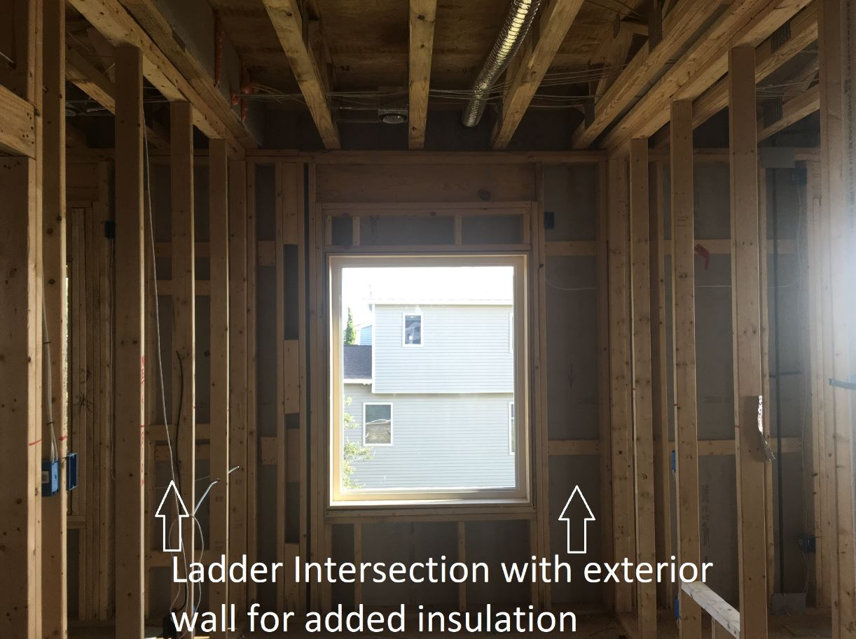
Construct framed walls using advanced framing details like framing aligned at interior/exterior wall intersections to reduce thermal bridging and allow more space for insulation.
- Allow room for insulation at interior-exterior wall intersections by installing ladder blocking, a full-length 2x6 or 1x6 nailer behind the first partition stud, or connecting the interior partition stud to the exterior top plate using a flat metal connector plate and using drywall clips to attach drywall.
- Fill exterior wall cavity space behind intersection with wall cavity insulation to full R value.
See the Compliance Tab for links to related codes and standards and voluntary federal energy-efficiency program requirements.
Description
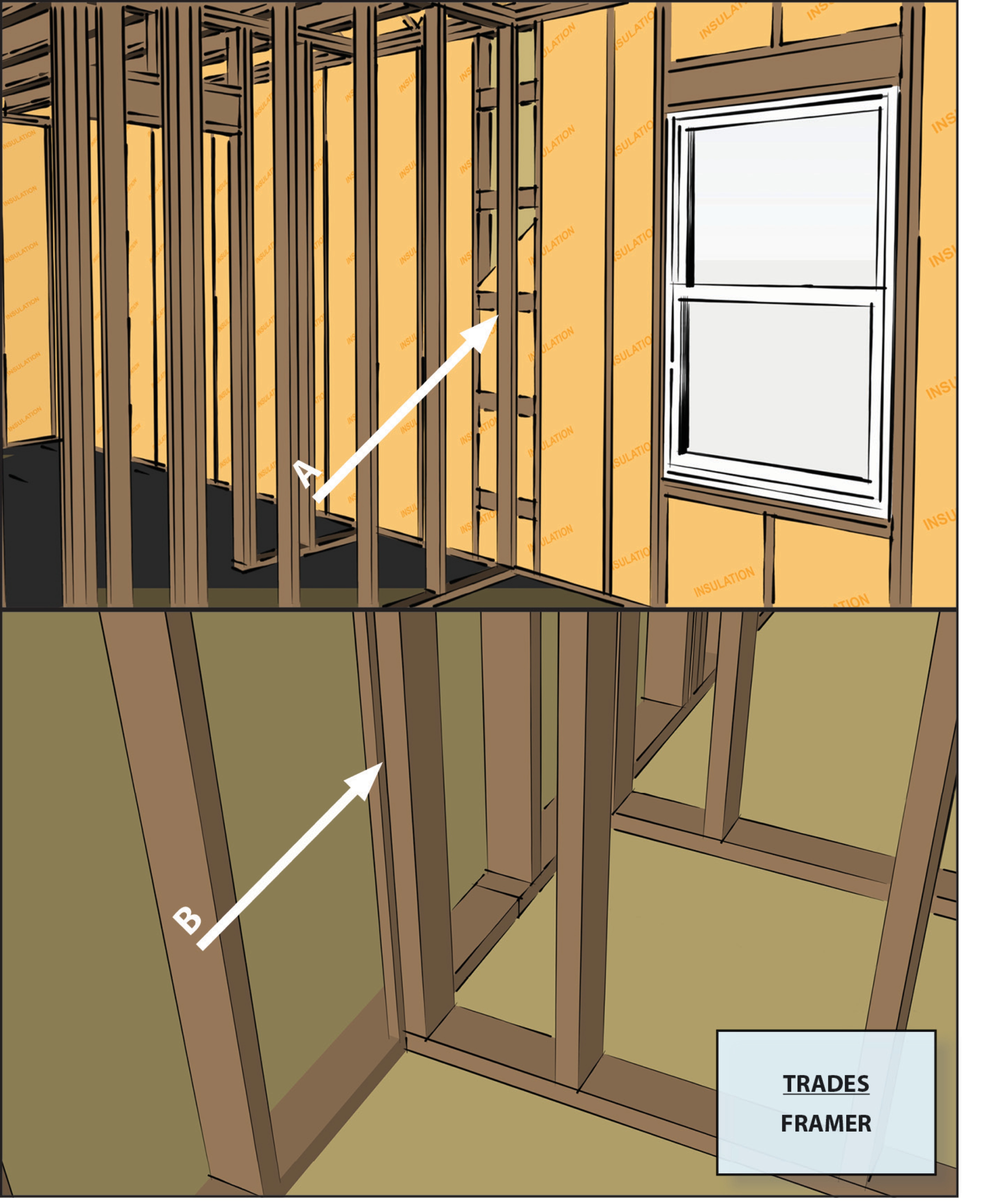
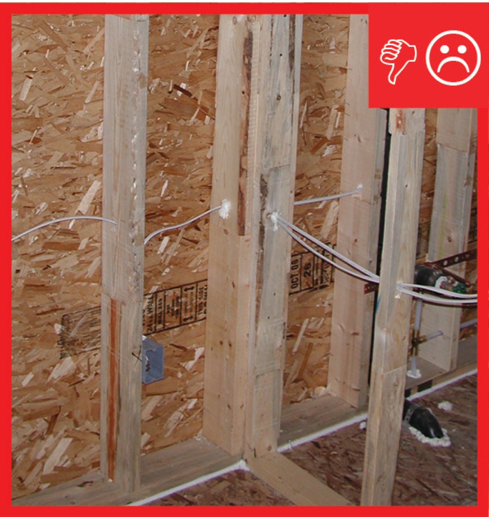
In stud-framed walls, where interior walls meet exterior walls, builders will typically use a conventional T-post detail. They will install two studs on the exterior wall, either touching each other or a few inches apart, at the location where the interior wall touches the exterior wall. The 2x4 stud at the end of the interior wall section is attached to these studs. If a few inches of space is left between these two exterior wall studs, insulation can be inserted in this space from outside before the exterior wall sheathing is installed; however, in practice the space rarely gets filled with insulation. This conventional framing method leaves uninsulated sections of exterior wall 3 to 6 inches in width everywhere an interior wall intersects an exterior wall.
Advanced framing techniques are described below that can be used to enable the installation of insulation along the exterior wall at the interior-exterior wall intersection.
These are some of several advanced wall framing techniques that can be employed by builders to increase energy savings by increasing insulation and reducing thermal bridging. Advanced framing also reduces costs by reducing lumber usage, materials waste, and labor time. See Minimum Wall Studs for more about advanced framing and for details on stud spacing and single top plates. Other advanced framing techniques are described in Insulated Corners, which explains how to construct corners with 2 studs instead of 3 studs to permit more insulation at the corners, Insulated Headers, which explains how and when to build open and insulated headers over windows and doors, and Minimal Framing at Doors/Windows for efficient framing around doors and windows.
Advanced framing techniques should be specified in the framer’s contract. Detailed framing elevations should be prepared after confirming permissibility in the local jurisdiction.

How to Install Advanced Framing at the Interior-Exterior Wall Intersections
There are three options: ladder blocking, use of a support post, or use of a connector plate and drywall clips.
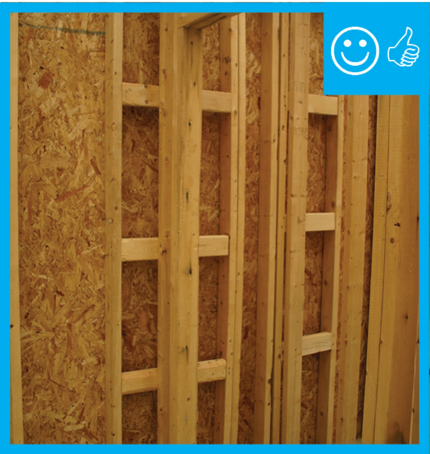
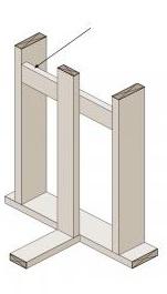
1. Ladder Blocking
- Install short sections of 2x4s horizontally between the studs on the exterior wall on each side of the interior-exterior wall intersection. Install them flush with the interior surface of the exterior wall studs at a spacing of 24 inches apart.
- Attach the 2x4 interior wall to these blocking pieces.
- Install insulation behind the blocking.


Source
Fact sheet describing advanced wall framing.
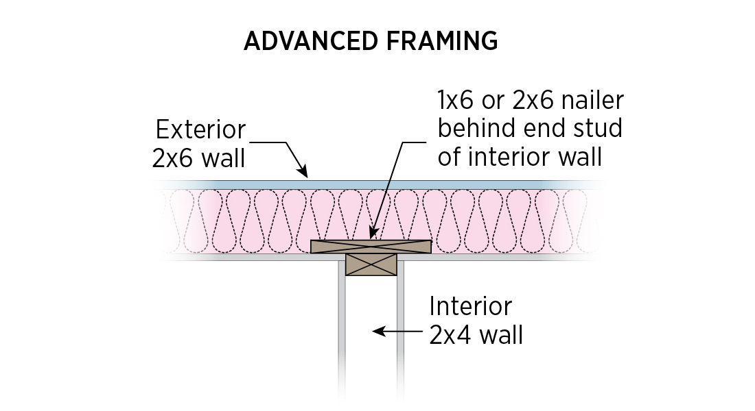
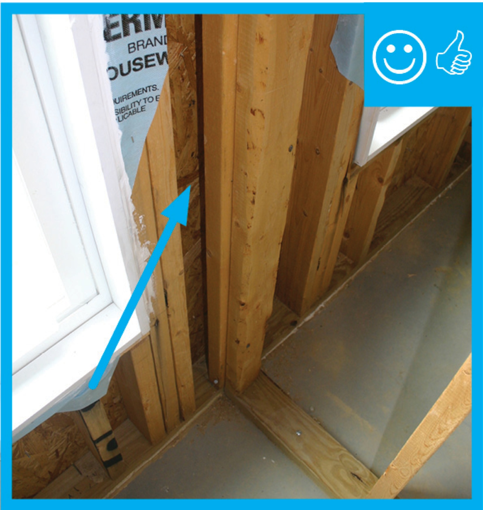
2. Support Post
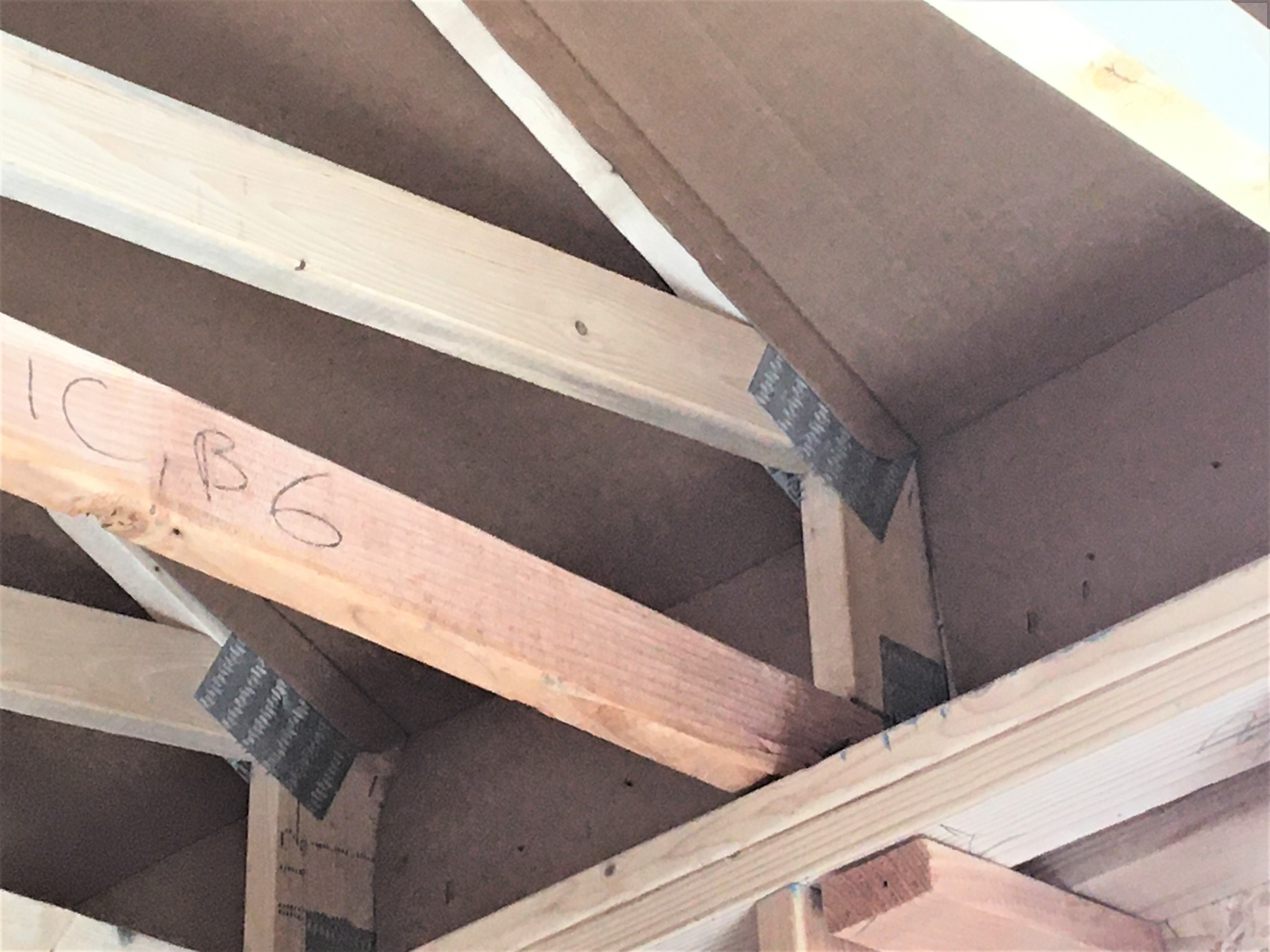
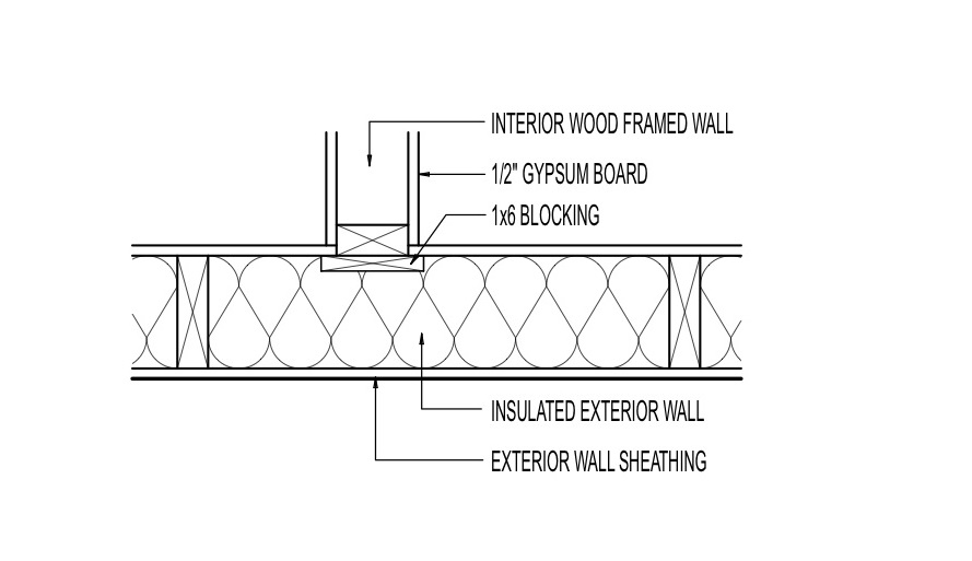
- Install a 1x6 or 2x6 support post on the exterior wall at the interior wall location, flush with the interior face of the wall. Attach it to the top plate and bottom plate.
- Attach the interior 2x4 wall to it.
- Insulate behind the post.

Source
Fact sheet describing advanced wall framing.
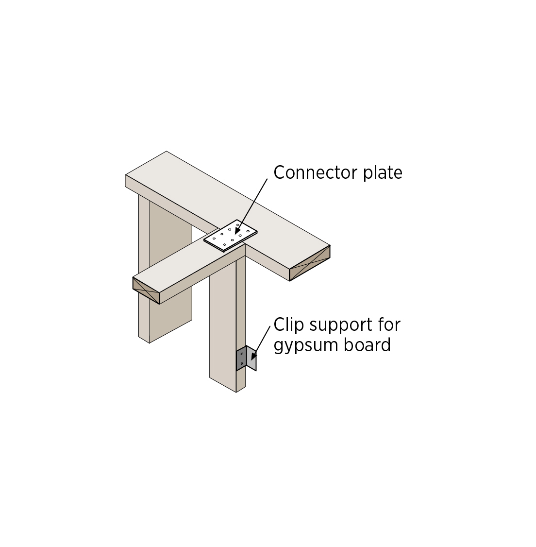
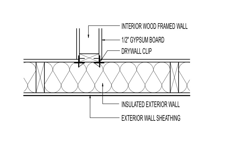
3. Connector Plate and Drywall Clips.
- Attach the interior 2x4 wall to the exterior wall top plate with a flat metal connector plate. Toenail the interior stud directly to the bottom plate.
Source
Report describing advanced framing techniques, including discussion of cost and energy savings.
2. Attach dry wall clips to the end stud of the interior wall to support drywall.
3. Insulate behind the post.

Source

Source
Presentation about advanced framing techniques.
Ensuring Success
Advanced framing details should be specified in the construction plans and reviewed with framers. The construction supervisor should ensure that framing crews are knowledgeable of or trained in advanced framing techniques. The framing should be visually inspected by the site supervisor before the drywall is installed.
Region
No climate specific information applies.
Training
Right and Wrong Images
Source
Guide describing details that serve as a visual reference for each of the line items in the Thermal Enclosure System Rater Checklist.
Source
Guide describing details that serve as a visual reference for each of the line items in the Thermal Enclosure System Rater Checklist.
Source
Guide describing details that serve as a visual reference for each of the line items in the Thermal Enclosure System Rater Checklist.
Source
Source
Source
CAD Files


More Info
Case Studies
References and Resources
*For non-dated media, such as websites, the date listed is the date accessed.
Contributors to this Guide
The following authors and organizations contributed to the content in this Guide.
Pacific Northwest National Laboratory
Building Science Corporation, lead for the Building Science Consortium (BSC), a DOE Building America Research Team
Sales
Adv. Int./Ext. Wall Intersections = High-Efficiency Wall Intersections
Technical Description
Heat loss often occurs where interior walls intersect with exterior walls in traditionally built homes because the additional studs required for nailing drywall leave minimal space for insulation. In contrast, high-efficiency wall intersections use techniques that require less wood, provide required nailing surfaces for drywall that meet at the corners, and allow more space for insulation. One method uses horizontal pieces of framing between the two exterior wall studs where an interior wall will intersect. This creates an appearance like a ladder. Another method uses a metal plate to connect the tops of the intersecting walls, along with clips on the studs to secure the drywall.
Questions? Comments? Contact our webmaster.