

Scope
Design a whole-house ventilation system that complies with all relevant codes and standards and provides adequate indoor air quality.
- Preliminary Planning
- Determine appropriate ventilation rates for the residence.
- Determine what code or program requirements must be met.
- Assess all planned ventilation systems (including local ventilation for kitchen and bathrooms).
- Assess heating and cooling systems, including duct work – especially if the ventilation system may be integrated with a central air handler or if indoor humidity control is needed.
- Determine and design an appropriate type of ventilation.
- Select a whole-house ventilation system that complies with ASHRAE 62.2 if required to meet state code or to meet project objectives.
- Install and commission the ventilation system.
For an overview of whole-building ventilation systems in existing homes, see the Building America Solution Center guide Whole-House Ventilation Strategies for Existing Homes; also see the Pre-Retrofit Assessment of Ventilation Systems. The Solution Center also contains installation guides for a variety of ventilation and air handler components. For information on indoor air quality, a common reason that people install ventilation systems, see the ASHRAE Residential Indoor Air Quality Guide (Schoen et al. 2018).
See the Compliance Tab for links to related codes and standards and voluntary federal energy-efficiency program requirements.
Description
The “appropriate” amount and type of ventilation varies from home to home and from occupant to occupant. Different households have different occupancy levels (people and pets), schedules, activities, health concerns, and other preferences that will influence appropriate ventilation systems and operations.
This BASC guide describes the three ventilation strategies typically considered for residential ventilation: exhaust-only systems, supply systems, and balanced systems. These ventilation strategies are described in greater detail in the section Types of Whole-House Systems below. See the section “Factors to Consider in Selecting a Ventilation System” below for other considerations including codes and standards related to ventilation, indoor air quality, humidity control, and cycling versus continuous ventilation.
This guide focuses on whole-house mechanical ventilation. Local exhaust ventilation, such as kitchen and bathroom exhaust fans, are typically intended to run intermittently to remove contaminants near where they are generated. Whole-house ventilation is intended to operate continuously (or at frequent, automated intervals) to provide ongoing fresh air and dilution of potential contaminants to meet ventilation levels that are desired or required by building codes or national home performance programs such as the DOE’s Zero Energy Ready Home program, ENERGY STAR Single-Family New Homes, and EPA Indoor airPLUS.
ASHRAE Standard 62.2 provides guidance for calculating minimum ventilation rates. Additional ventilation and other IAQ-related measures may be needed to account for varying occupancy levels and conditions. See the section below on codes and standards and the Compliance tab for more information on this standard (including changes in recent editions) and other codes and standards related to ventilation.
Types of Whole-House Ventilation Systems
There are three common mechanical ventilation strategies used in residential buildings.
These systems include
- Exhaust-only - Exhaust-only systems use kitchen, bath, and/or laundry fans to exhaust stale air locally and from the whole house; the exhausted air is replaced by air that is pulled in through leaks in the building envelope or through passive vents. The fans are set to run continuously or intermittently on timer controls.
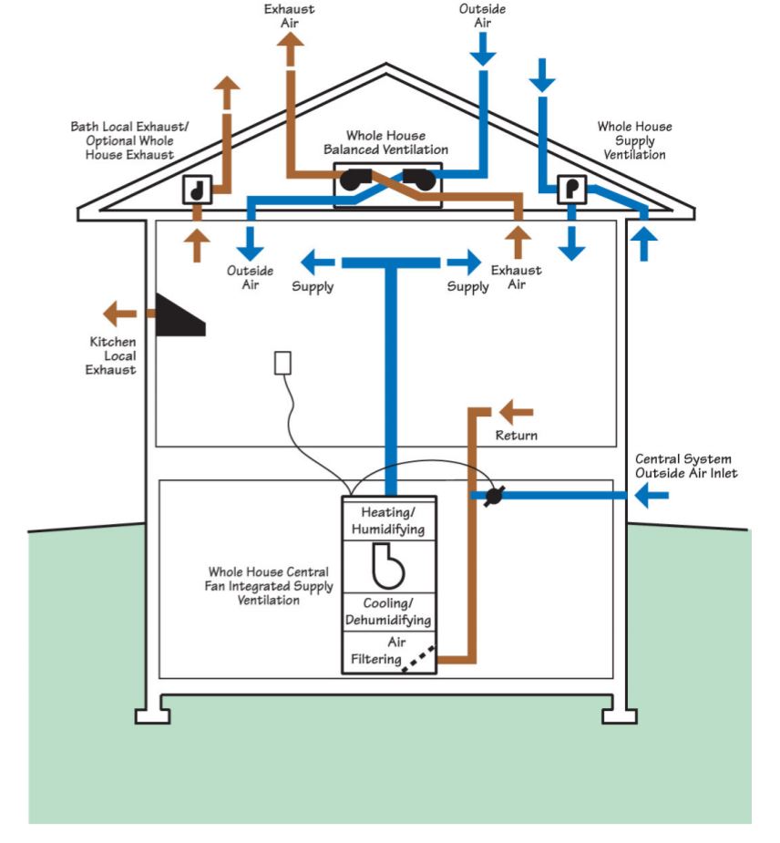
- Supply - Central fan-integrated supply ventilation provides outdoor air through an outdoor air intake that is ducted to the return side of the home’s central heating and cooling system air handler for filtering, heating or cooling, and distribution to the house through the HVAC system ducts.
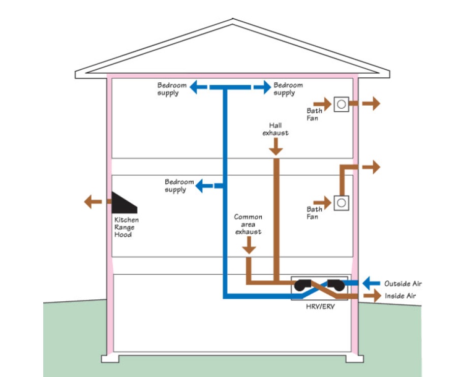
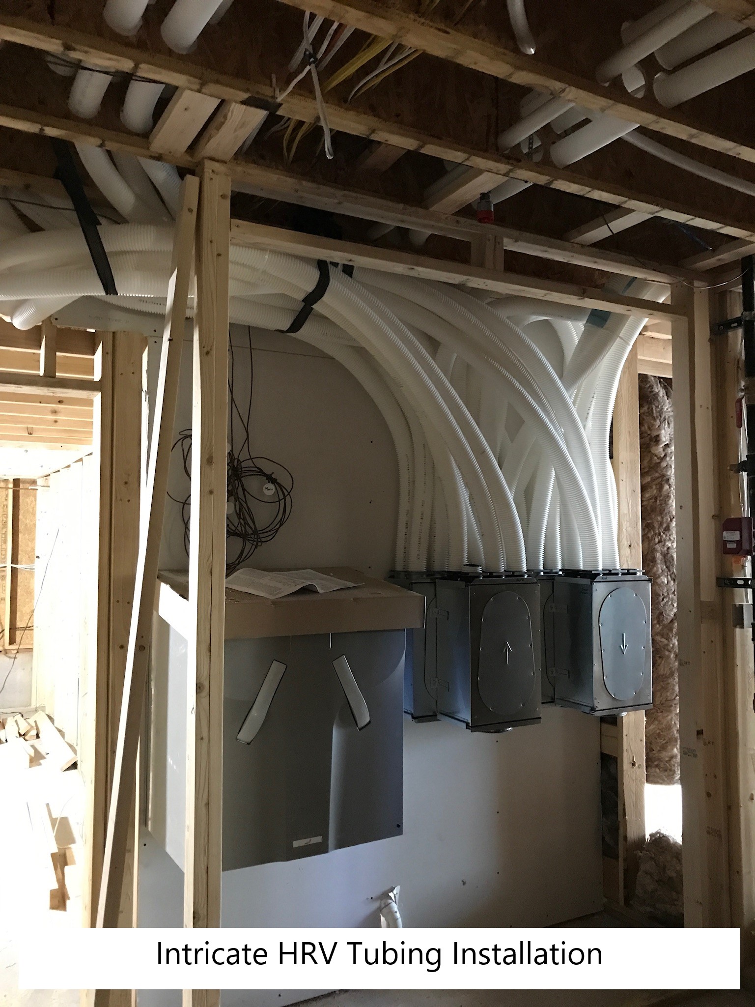
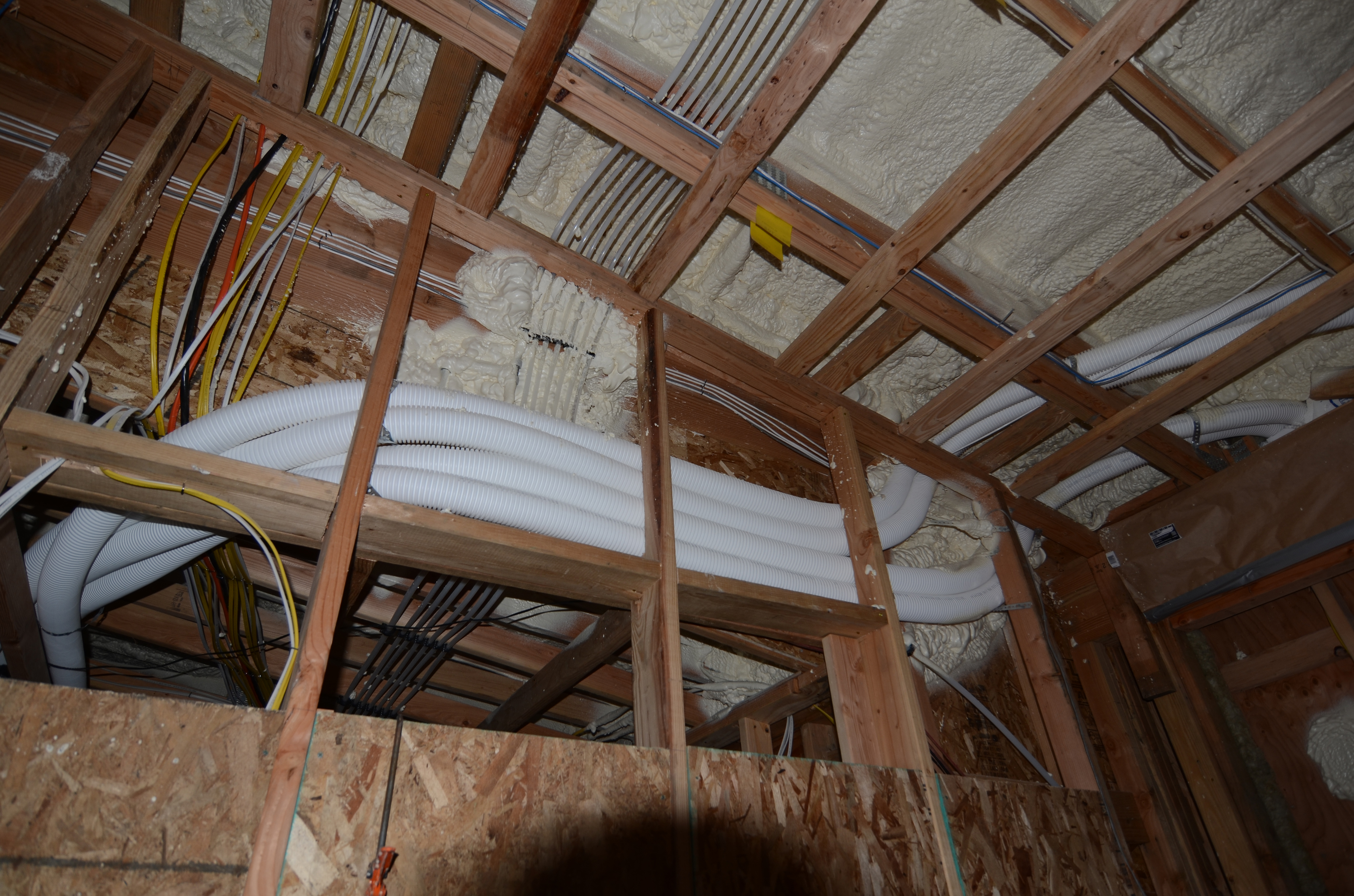
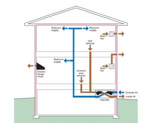
- Balanced - Heat recovery ventilators (HRVs) simultaneously bring in outdoor air and exhaust indoor air, with both ducts passing through a heat exchanger for heat recovery. Energy recovery ventilators (ERVs), function like HRVs but move to transfer both heat and moisture. ERVs and HRVs may be connected to the home’s central air handler and duct system or independently ducted.
These three strategies are illustrated in Figure 1 and described below. Further information, including details on commissioning, can be found in the Solution Center guide Whole-House Ventilation Strategies for Existing Homes.
Supply-Only Ventilation
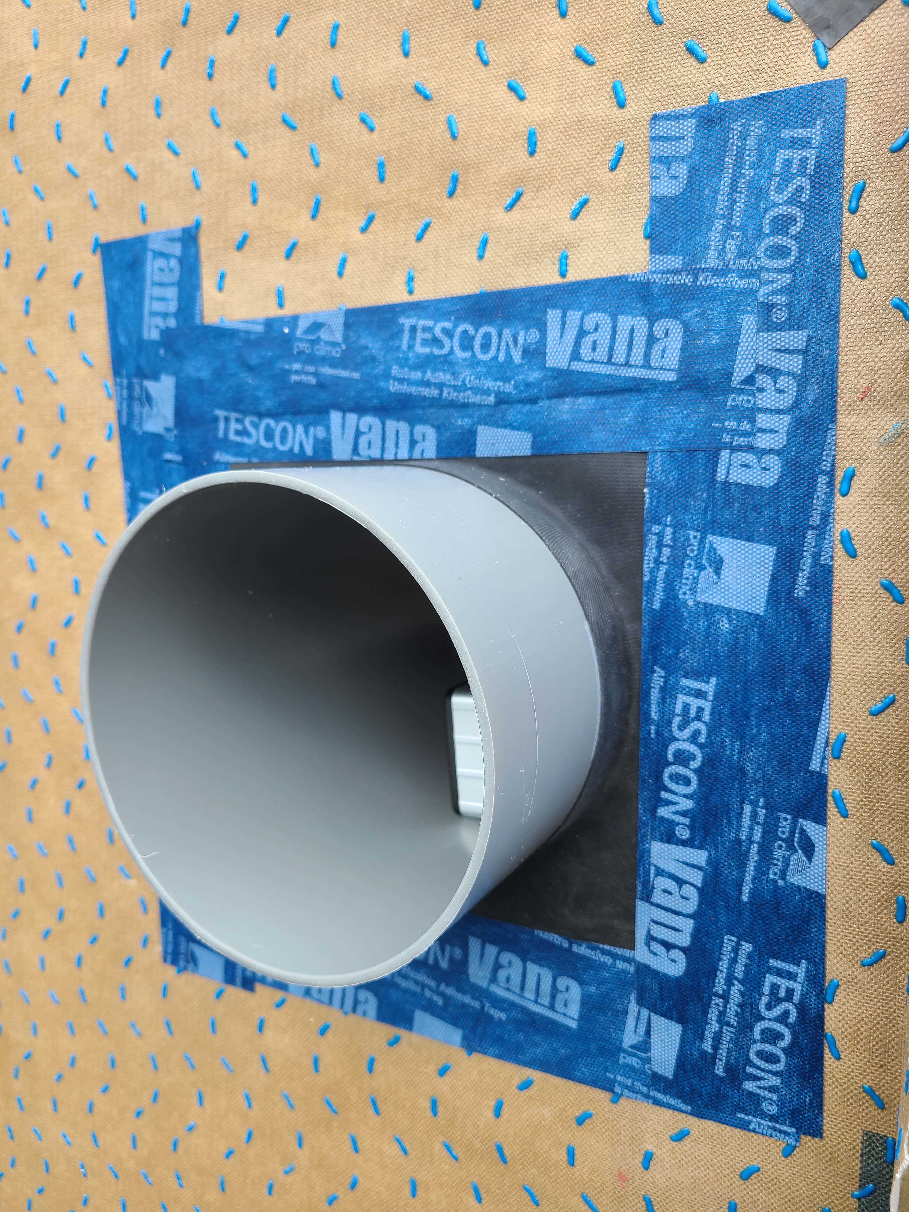
Supply-only ventilation uses either the HVAC system central supply fan or an in-duct fan to pull in air from outdoors through a dedicated outdoor air intake. With supply ventilation, outdoor air enters the building from a known location and stale air leaves the building through an unknown location (through leaks in the building shell or through exhausting appliances such as exhaust fans, clothes dryers, and fireplaces). Care should be taken in siting outdoor air inlets to allow access for maintenance and air flow verification and commissioning. Outdoor air intakes should be at least 10 feet from the nearest exhaust or sanitary vent termination point or other contamination source, like exhausting cars.
Supply ventilation will create a positive pressure in the conditioned space relative to the outdoors. If the systems in Figures 2 and 3 were drawing 80 CFM of outdoor air into the home while the air handler is operating, then, at the same time 80 CFM must be exiting the building somewhere. That "somewhere" is the many leaks in the building envelope that connect indoors to outdoors. In humid climates, if the conditioned indoor air is drier than the outdoor air (for example in large homes during the cooling season when the air conditioner is running often), this is a good strategy as it can help keep the building envelope materials (the insides of the walls) dry. In cold dry climates where indoor air is more humid than outdoor air (in high-performance buildings), supply-only ventilation would be a poor ventilation strategy. Supply ventilation may not be a good strategy in high-performance homes that have tight envelopes and low cooling loads, and therefore lower air conditioning run times. Indoor humidity could also increase in all homes in shoulder seasons when the system is not calling for much air cooling, thus increasing the need for supplemental dehumidification.
One common type of supply ventilation system is known as central fan integrated supply ventilation (CFIS). When the cooling or heating system is energized, outdoor air is drawn in through a filtered intake grille and is ducted directly to the return side plenum of the HVAC system's central air handler as shown in Figure 3. The air is tempered by the air handler, then circulated throughout the building through the HVAC system ducts.
The outdoor air duct has a balancing damper (BD), which can be manually or electronically set to adjust the amount of incoming outside air to meet the target cubic feet per minute flow rate determined in the ASHRAE 62.2-2019 calculations.
For systems using the central forced air HVAC system, the success of this strategy is dependent upon good design: an accurate HVAC load calculation, installation of HVAC equipment that closely matches the load, and a properly designed HVAC duct system with low air leakage – a reasonable target would be cfm50 < 10cfm. It is imperative that the ventilation controls take into account cooling system operation and curtail ventilation at the end of cooling cycles in order to not evaporate water off the coil that could lead to poor humidity control. The controls should also control ventilation to meet the minimum requirements of ASHRAE 62.2-2019 and not only operate when the HVAC system is heating or cooling.
The pros and cons of CFIS systems are shown in Table 1. CFIS systems can consume large amounts of electricity because the large central fan is turning on just to circulate fresh air, and a central fan would typically be moving much more air at higher power consumption than is needed for this use. However, variable-speed fans with ECM motors can modulate down to a lower flow rate when in ventilation-only mode. If using a relatively efficient AHU fan motor (300 Watts) and running an average of 8 h/day for ventilation (i.e., in addition to operation needed for space conditioning), a CFIS would consume 876 kWh/yr. At $0.11/kWh, this costs $96/yr. Most central air handlers have motors that are not this efficient, so it is not uncommon for power draws to be two or three times higher.
Basic CFIS systems have no heat recovery, and outdoor air brought into the building is tempered by mixing with return air. However, overall equipment expenses are low since this ventilation method would only be chosen if the house design already has a ducted HVAC system with a central air handler or central furnace.
In a humid climate, to meet ASHRAE 62.2, active dehumidification may need to be added to the run-time vent system to handle the moisture that is brought in during the shoulder seasons when the damper is open and the compressor is not operating, depending on the size and type of air conditioning system installed. For example, in Florida, when it is 95°F outside, the compressor (AC) in a typical existing house with a large single-stage AC runs about 80% of the time. When it is 80°F outside, the compressor only runs about 40% to 50% of the time. The dehumidifier can be a separate unit attached to the central air handler or a stand-alone unit. The pros and cons of CFIS systems are outlined in Table 1.
| CFIS Pros | CFIS Cons |
|---|---|
| Simple and affordable to install, uses existing ducts and blower fan. | Home must have a central forced-air heating and cooling system |
| Distributed outdoor air to all parts of home | Higher electricity consumption. Recommended for central air handlers with ECM blower motors |
| Low maintenance | If duct system is leaky, heating and cooling penalties could be high |
| Outdoor air is drawn from a known location | Could cause comfort issues during very cold or very holt humid conditions |
| Outdoor air is filtered, at intake and at central air handler | Hard to commission |
| Outdoor air is tempered thru central HVAC | Low intake air flow rate |
Exhaust-Only Ventilation
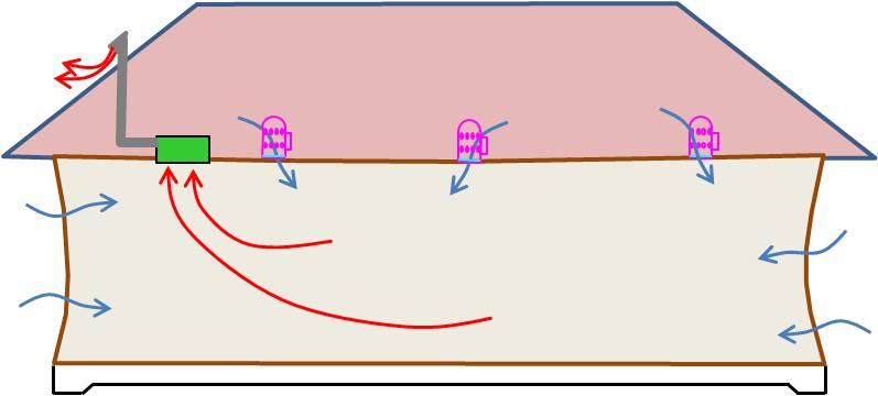
Exhaust-only ventilation is the reverse of supply-only ventilation; stale air leaves the building from a known location (through exhaust fans ducted to the outdoors) and outdoor air enters the building from an unknown location. Exhaust-only ventilation strategies use exhaust fans located in the bathroom, kitchen, laundry room, or some central location to pull moisture and contaminants out of the home. For more information on selecting and installing kitchen and bath fans for local and whole-house ventilation, see the Solution Center guides Bathroom Exhaust Fans and Kitchen Exhaust Fans.
Exhaust fans can depressurize the home (Figure 4). For every cubic foot of air exhausted out of the building, a cubic foot of air has to come into the building from somewhere. Again, that "somewhere" is the many air leaks through the building envelope that connect the conditioned space to unconditioned spaces or directly to the outdoors. With this strategy, the outdoor air entering the building is not directly filtered or conditioned. While a typical new home envelope filters particles roughly equivalent to a MERV 8 filter and provides some heat recovery, this is not done in a controlled manner – particles are filtered out as air is pulled in through cracks in the building envelope, not through filters. The target ventilation rate is met by operating a (quiet) exhaust fan at a specific flow rate for a scheduled runtime each hour.
The exhaust-only strategy works well in cold-dry climates because the air outdoors is generally drier than the air indoors (in tightly built homes). Unlike the older leaky homes built years ago, newer high-performance homes are built to be more air tight so they tend to accumulate more moisture as water vapor in the indoor air from cooking, bathing, clothes washing, etc. Exhaust fans are needed to safely remove this moisture before condensation becomes an issue. This makes the installation and operation of kitchen, bath, and laundry room local exhausts very important in these homes. The pros and cons of exhaust-only dwelling unit ventilation systems are shown in Table 2.
This strategy should be used with caution in humid climates where the dewpoint outdoors is sometimes lower than indoor temperatures for considerable periods of time, for example, vapor-impermeable interior finishings, such as vinyl wallpaper, should not be used.
Once the desired flow rates are known (based on a calculation to meet code-required ventilation rates, like ASHRAE 62.2; see the Codes and Standards section below), it’s usually best to select an exhaust fan that meets these flow rates at pressures of 0.25 inches water column (in. w.c.). Many fans list flow rates at 0.1 in. w.c., but most exhaust duct runs have much higher pressure drops.
ENERGY STAR-rated exhaust fans are recommended for most applications; the most obvious benefit of these fans is lower energy consumption. ENERGY STAR requirements for bathroom exhaust fans (with rated flow rates below 90 cfm) call for fans to deliver a minimum of 2.8 cfm/Watt. For fans with rated flows of 90 to 200 cfm, ENERGY STAR fans must deliver at least 3.5 cfm/Watt. See the Building America Solution Center guides Continuous Supply/Exhaust Fan Ratings and Intermittent Supply/Exhaust Fan Ratings for information on assessing fan ratings. Exhaust-only systems like kitchen and bath fans can provide intermittent local ventilation and/or whole-house ventilation.
While these energy requirements represent great improvements over older fans, many manufacturers now have bathroom exhaust fans with efficacies of more than 10 cfm/Watt. These very efficient fans typically use brushless permanent-magnet motors (BPM motors). These motors are also referred to as DC (direct current) motors, ECMs (electronically commutated motors), or variable-speed motors. In addition to lower energy consumption, the variable-speed capabilities of these motors allow these fans to maintain design flow rates over a wide range of static pressures.
The pros and cons of the exhaust-only ventilation approach are shown in Table 2.
| Exhaust-Only Pros | Exhaust-Only Cons |
|---|---|
| Low cost for fan equipment and operation | May depressurize home |
| Easy to install – most homes already have one or more exhaust fans and ducting so upgrading to a high-performance model is easy | Point-source, does not draw air evenly from all parts of the home so ventilation and air mixing is not likely to be consistent across the home |
| Easy to test and commission | No energy recovery |
| Uses very little energy – 5 to 12 Watts for 50 to 80 cfm flow rate | Intake air may come from infiltration through cracks in building envelope rather than from controlled, filtered sources |
| Highly reliable | Easy for homeowner to override |
| Quiet operation | |
| Adjustable flow rate | |
| Can be timer controlled | |
| Require very little maintenance | |
| Some filtration and tempering provided through the building envelope | |
| Works with ductless heating and cooling |
Balanced Ventilation
Balanced systems intentionally provide both supply and exhaust. The incoming and outgoing air volumes are balanced; thus, the house is neither pressurized nor depressurized.
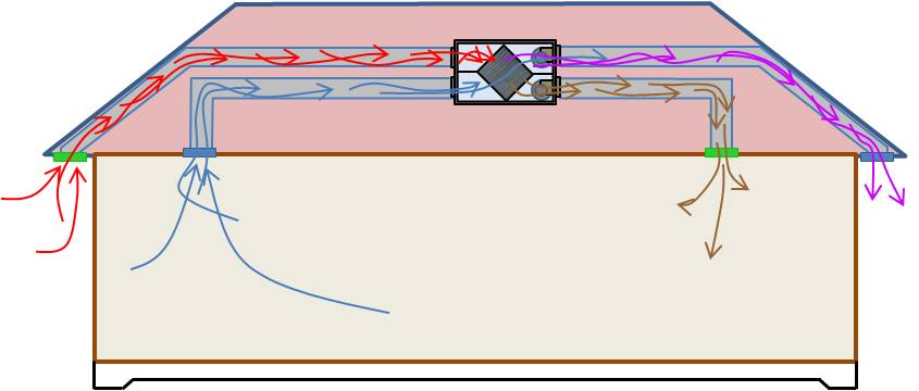
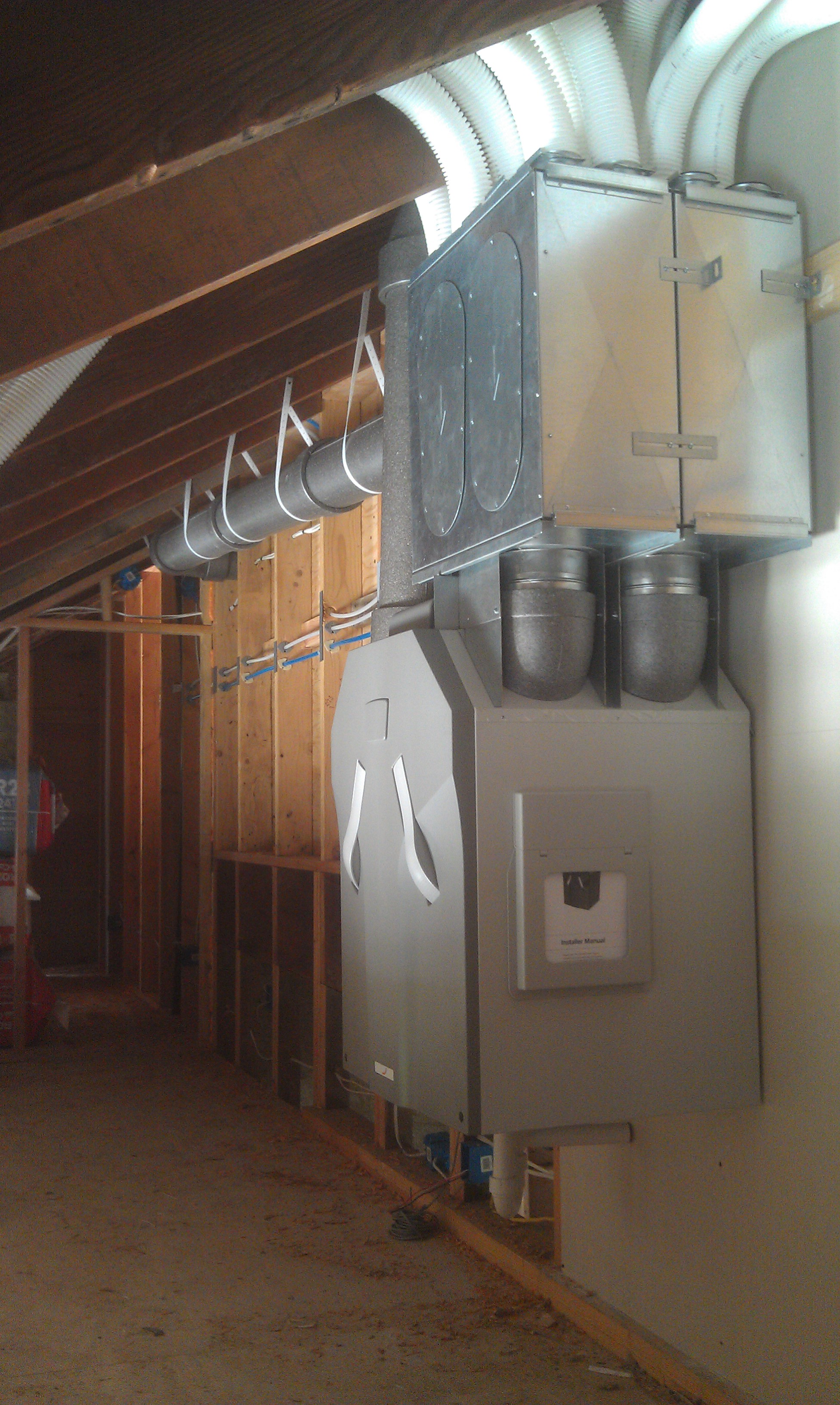
The best means for providing this balanced ventilation is with a heat recovery ventilator (HRV) or an energy (or enthalpy) recovery ventilator (ERV) (Figures 5 and 6). These systems provide a controlled way of ventilating a home while minimizing energy loss. The systems have an incoming duct that brings outside air into the home and outgoing duct that removes stale air from the home. The two ducts cross in a heat exchanger where heat is transferred heat from the warmer duct to the cooler duct. In the winter, heat from the outgoing air is transferred to the incoming cold air; in summer, heat from the incoming air is transferred to the cooler exhaust air. The incoming air can be evenly distributed throughout the house via the central air handler and duct system. Or, ideally, these systems can have their own duct system. The main difference between an HRV and an ERV is that an ERV is able to transfer moisture as well as heat from the more humid air to the drier air.
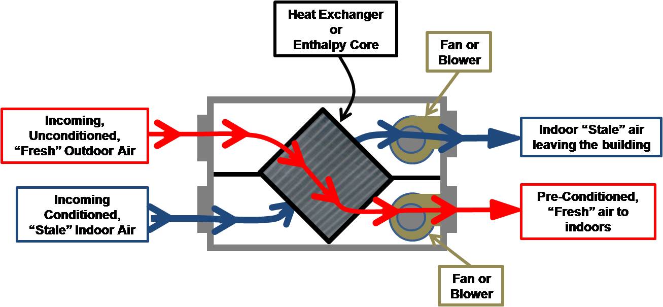
See the manufacturers' specifications for determining which model is best in which climate and install it according to their directions for best performance, especially in regard to ERVs in humid climates. Most ERVs can recover about 70% to 80% of the sensible energy in the exiting air (Rudd 2011). With respect to summertime operation, ERVs seem to perform best during peak outdoor conditions and lose efficiency during low-temperature, high-humidity conditions. The pros and cons of HRV and ERV systems are presented in Table 3.
| HRV/ERV Pros | HRV/ERV Cons |
|---|---|
| Heat and Moisture transfer tempera air | Higher cost |
| Can distribute ventilation air to many parts of home | More maintenance, regular filter replacement |
| Doesn't induce large pressure differences in the homes | Energy savings varies |
| May be difficult to install and commission | |
| Noise |
Intermittently Balanced
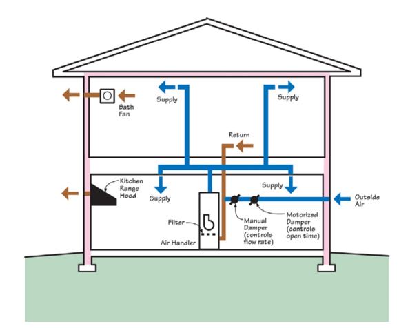
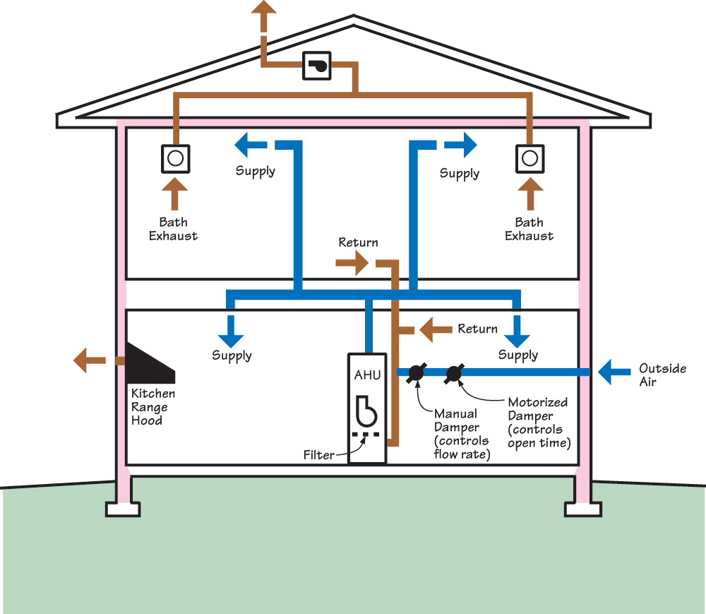
Another ventilation strategy is the "intermittently balanced" system, which combines supply and exhaust but does not include an HRV or ERV (Rudd 2011). Supply and exhaust ventilation systems are combined to make use of the benefits and economies of each system, although the net result may be an alternating unbalanced system (sometimes more supply ventilation, sometimes more exhaust ventilation) or an intermittently balanced system. To fully balance the system requires fans and dampers to be carefully controlled with electronic controllers to provide equal amounts of incoming and outgoing air. An example of this type of system could be central-fan-integrated supply ventilation with simultaneous continuous or intermittent exhaust. Another example would be the use of inline fans in the wall or ducted bring outside air into the home through one or more supply grilles while one or more exhaust fans are operating, ideally in other parts of the house to exhaust air from the home. The fans are operated concurrently at similar air flow rates to provide ventilation while keeping pressures in the home balanced. An example of such a system is shown in Figure 7.
Factors to Consider in Selecting a Ventilation System
There are many different strategies and products for delivering ventilation air to a dwelling. Some of these methods are not appropriate in certain climates, and each has potential benefits and limitations. Efficiencies and performance for various ventilation products can be found in the Certified Home Ventilating Products Directory. Efficiencies for dehumidifiers, room air conditioners, and room air cleaners are tested by independent laboratories and reported by the Association of Home Appliance Manufacturers.
The designer should select a system based not only on its cost but also on its suitability for the climate, ability to filter contaminated outdoor air, compatibility with the heating and/or cooling systems, potential to exacerbate moisture problems, acceptability to occupants, and energy use. Specific factors to consider include codes and standards that are applicable to the project, indoor air quality considerations, the need for humidity control, depressurization issues (especially if combustion appliances with non-sealed combustion chambers are located in the home), and the need or desire for cycling versus continuous ventilation in the home.
Codes and Standards Related to Ventilation
(The following is excerpted from the ASHRAE Residential Indoor Air Quality Guide (Schoen et al. 2018).
The 2012, 2015, and 2018 International Residential Code (IRC) require whole-house mechanical ventilation for relatively air-tight homes. The ventilation flow rates are similar to those required in ASHRAE 62.2-2010. The codes do not have credits for infiltration as do the ASHRAE standards.
The 2015 International Mechanical Code (IMC), which covers most multifamily dwelling units (those not covered by the IRC, discussed below), requires all occupiable spaces to have natural or mechanical ventilation. It also requires mechanical ventilation in dwelling units with an air infiltration rate of less than 5 ACH 50 when tested with a blower door (described in detail in Strategy 1.4). If the jurisdiction also adopts the International Energy Conservation Code (IECC) without amendments, a blower door test of 5 ACH50 or less is required, but the IMC does not require it directly. Even if both codes are adopted, this cross-referencing of the two codes can be easily overlooked or neglected, creating an effective loophole. As a result, many multifamily dwellings still rely in whole or in part on operable windows and doors to provide the code-required ventilation. This is not good practice because people do not open windows often enough to meet ventilation requirements.
The IRC, which covers detached one- and two-family dwellings and townhouses not more than three stories high with their own entrance from the street, has a section on energy efficiency that requires air leakage of 5 ACH 50 or less in all climate zones (Figure 1.2-A) and specifically requires mechanical ventilation. Increasing numbers of jurisdictions continue to adopt requirements for mechanical ventilation for new dwellings. The latest versions of ASHRAE Standard 62.2 (2019) and local codes provide the minimum ventilation rate for a particular dwelling unit.
It can take time for the model codes to adopt rates published in ASHRAE Standard 62.2 and even more time for local jurisdictions to adopt the model codes. Jurisdictions also sometimes edit the model codes before adopting them. Therefore, the ventilation rates in ASHRAE Standard 62.2 are often higher than those required by local codes. ASHRAE recommends that the minimum rates in ASHRAE Standard 62.2 be adopted as a best practice.
Indoor Air Quality
The ASHRAE Residential Indoor Air Quality Guide (Schoen et al. 2018) states that, although building codes and standards have addressed outdoor air ventilation for decades, many dwellings are poorly ventilated, which increases the likelihood of poor indoor air quality (IAQ). The many potential causes of inadequate ventilation include lack of compliance with applicable codes and standards, installation or maintenance problems that prevent delivery of the target ventilation rate, or incorrect use of the installed systems by occupants. ASHRAE Standard 62.2 (ASHRAE 2019) covers the determination of target ventilation rates and fan sizing calculations.
After source control, air changes in a home are the most important factor for decreasing pollution concentrations. In existing homes with natural air change rates above 0.35 ACH, ventilation occurs somewhat naturally through gaps and cracks in the enclosure. In newer homes, with natural air change rates less than 0.35 ACH, additional mechanical ventilation has been shown to help decrease pollutant concentrations of dangerous aldehydes like formaldehyde and acetaldehyde.
Lawrence Berkeley National Laboratory has compiled an extensive guide to ventilation for new and older homes called Ventilate Right: Ventilation Guide for New and Existing California Homes that provides detailed information on options in ventilation equipment, along with a multi-step process for selecting, installing, and commissioning home ventilation equipment.
The ASHRAE IAQ guide also points out issues in addition to ventilation rates that can influence IAQ. These include the following:
- Lack of quality control in the design and installation of heating, air conditioning, and ventilation systems
- Moisture in the enclosure from leaks and humidity
- Poor outdoor air quality
- Moisture and dirt in the ventilation systems
- Indoor contaminant sources such as off-gassing cabinetry, carpet adhesives and carpet, cleansers, paints, and finishes.
- Ineffective filtration and air cleaning
- Poor air distribution which can under-ventilate some portions of the dwelling
- Local radon and exhaust.
Other BASC guides provide best practices for addressing many of these issues, such as the guides linked to the EPA Indoor airPLUS checklist.
Indoor air quality sensors for homes are becoming more readily available. These can be stand-alone sensors or they can sometimes be wired to work with controls to activate or increase ventilation rates in the home to address elevated moisture or contaminant levels due to activities in the home such as cooking or showering or increased occupant levels. These sensors can automatically activate ventilation systems or work with home automation systems to alert occupants to activate more ventilation. Sensors can also be used with controls to shut outdoor air intakes if there are unacceptable air quality conditions outside such as elevated humidity, smoke, or particulates in the air.
Humidity Control
Achieving ASHRAE 62.2 ventilation requirements may increase the moisture content in the indoor space, especially in humid climates. High indoor humidity can have a negative effect on thermal comfort and can contribute to problems with biological growth. (For more on how ventilation impacts humidity rates, see the report Impact of Residential Mechanical Ventilation on Energy Cost and Humidity Control by Martin 2014.) In many dwellings, simply operating a properly sized air conditioner or heat pump to cool the dwelling is enough to adequately control humidity because dehumidification will also occur when indoor air is cooled with a refrigerant air cooling system. However, the cooling system is set to control temperature, not humidity level. When the indoor humidity level rises, the system does not necessarily respond by performing more dehumidification unless the dwelling also happens to need cooling. Proper equipment sizing as described in the Air Conditioning Contractors of America (ACCA) manuals, such as ACCA Manual S - Residential Equipment Selection and ACCA Manual J - Residential Load Calculation can improve dehumidification, but some dwellings need more dehumidification than the cooling system can provide. These dwellings need a dehumidifier.
Dehumidifiers include stand-alone dehumidifiers, which are often installed in sealed basements and crawlspaces; ducted dehumidifiers, which are integrated with a dwelling’s air handler; and dehumidifier-ventilators, which can dehumidify outside air brought into the home for ventilation. Supplemental dehumidification is often necessary for dwellings in humid climates. Very energy-efficient dwellings and below-grade spaces, which are both likely to use less air conditioning, are more likely to need dehumidifiers. Dehumidifiers can use a substantial amount of energy and not every dwelling needs one. However, when additional dehumidification is necessary, the dehumidification is worth the cost according to the ASHRAE Residential Indoor Air Quality Guide (Schoen et al. 2018).
Not all excess humidity problems are best solved with a dehumidifier. As with other air contaminants, the first choice is to control moisture at the source. Houses should be designed with appropriate flashing and weather screens to avoid moisture intrusion, with moisture retarders to avoid vapor transport, and with adequate and continuous thermal insulation, including highly insulating windows, to avoid the formation of condensation and ice. Search the Building America Solution Center to find guides on appropriate envelope measures.
Kitchen and bathroom exhaust fans can control moisture at key points in the home where large amounts of moisture may be produced.
Dwellings in climates that can have very cold outdoor temperatures can also experience very dry conditions where a humidifier is desired for occupant comfort. However, humidification can threaten IAQ when the system malfunctions, is operated at a higher humidity setting than appropriate, or is allowed to develop biological growth. See the ASHRAE Residential Indoor Air Quality Guide (Schoen et al. 2018) for strategies, case studies, and other information on humidity control.
Depressurization and Other Issues with Ventilation Systems
Ventilation systems, including exhaust-only systems and improperly balanced ERVs and HRVs, can depressurize a home, pulling more air from the home than is brought into the home. Wind and stack pressure can contribute to house depressurization. Large range hood fans, clothes dryers, and fireplaces also contribute to house depressurization of the home if makeup air is not provided.
Depressurization can contribute to indoor air quality issues as follows:
- Depressurizing the home can interfere with any natural-draft combustion appliances located in the home. A home energy rater or HVAC contractor can perform standardized test procedures to assess this issue. Best practice is to remove and replace natural-draft combustion appliances with direct-vent sealed-combustion appliances or noncombustion appliances.
- In a home with an attached garage, depressurization could pull garage air into the home. The wall separating the house from the garage should be completely air sealed and HVAC ducts should not be located in the garage. House pressurization testing can be conducted to confirm the air tightness of the wall between the house and the garage. An exhaust fan can be installed in the garage to exhaust garage air directly to the outside, and to keep the garage at negative pressure with respect to the living space of the home.
- Depressurization of the home has the potential to bring in air and contaminants from basements, crawlspaces, attics, or attached dwelling units if the building envelope is not well sealed; however, if outside air is coming into the home through a leaky building envelope it would likely dilute incoming contaminants. A radon mitigation system should be installed if radon testing shows unacceptable levels of radon. (See the Building America Solution Center guides Radon Fan and Vertical Radon Ventilation Pipe for more information on radon mitigation systems.)
- Any existing ventilation system, whether exhaust fans, ERVs, HRVs, or central fan integrated supply systems, should be assessed for effectiveness and any new systems that are installed should be commissioned by a trained HVAC technician or energy rater to verify performance.
Cycling versus Continuous Ventilation
(The following is excerpted from the ASHRAE Residential Indoor Air Quality Guide (Schoen et al. 2018).)
The ventilation rates in most codes and standards are for continuously operating systems. Sometimes, it is desirable to operate the system for less time at a higher airflow rate. There are several reasons to cycle systems. For example, when the fan used for ventilation is also used for heating or cooling, it can consume significant amounts of energy. Cycling the system to turn on for 20 minutes or less per hour is a good energy-saving strategy, particularly when it is combined with a smart controller that accounts for system runtime when the system is heating or cooling the dwelling. A smart controller set for 20 minutes per hour will only add system runtime if the system doesn’t operate for at least 20 minutes per hour to provide heating or cooling. Another reason to cycle a system is that stand-alone ventilation fans (e.g., exhaust fans and energy recovery ventilators) are available in discrete size increments, and cycling allows use of larger fans than are needed, without over-ventilating the dwelling.
Most mechanical ventilation systems that use cycling operate for a designated number of minutes each hour at a proportionally higher flow rate. For example, a dwelling unit that needs 50 CFM (23.6 l/s) of continuous ventilation could be served by 150 CFM (70.8 l/s) of ventilation air for 20 minutes each hour. Fan-cycling controllers are readily available for both supply and exhaust fans. Most controllers are designed for one-hour cycles and the occupant can adjust the number of minutes the fan is on each hour. Some controllers also allow occupants to increase the length of the cycle to more than one hour.
Mechanical ventilation systems that are designed to operate in cycles must be designed to move more air than those that run continuously. One benefit of this extra capacity is that the fan can temporarily run continuously when a highly polluting activity, such as painting or cleaning, is done indoors.
Cycle times longer than one hour can be used in locations with a significant energy or IAQ penalty associated with operating the ventilation system at certain times of the day. For example, a large energy advantage can be associated with ventilating a dwelling in a desert climate at night, when the air is cooler. In some locations, outdoor ozone or PM concentrations can be elevated at certain times of day and ventilating the dwelling at other times can be beneficial (Strategy 3.1). Because longer cycles can raise short-term contaminant concentrations, ASHRAE Standard 62.2 (ASHRAE 2016b) requires more total ventilation when the cycle is longer than three hours. The standard includes a calculation that accommodates a variety of approaches.
How to Calculate the Target Ventilation Rate for a Whole-House Ventilation System
Calculate the target ventilation rate for the home based on the square footage of floor area and number of bedrooms, using Formula 4.1a in ASHRAE 62.2-2010, shown in Figure 8 below. Note, in ASHRAE 62.2-2013 through 2019, the 0.01A is replaced with 0.03A.
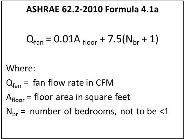
Figure 8. Formula for Calculating Target Ventilation Rate. (Source: ASHRAE 62.2-2010.) - Once the target ventilation has been identified, select a ventilation strategy that will best do the job given the climate.
- Determine the operating time - how long will the fan have to run to supply the target ventilation for each 24-hour period?
- Install the system according to the manufacturer's specifications.
Example: For a 3-bedroom, 2,000-sq.ft. home with an exhaust-only ventilation strategy and a target ventilation rate of 50 CFM, you would need to install a 50-CFM fan with an adjustable-speed DC motor for continuous operation. If you wanted to install a 100-CFM fan instead, you could determine what the run time would need to be using the formula below (Figure 9), from ASHRAE 62.2-2010. See the Compliance tab of this guide and see ASHRAE 62.2-2019 for a newer versions of this formula.
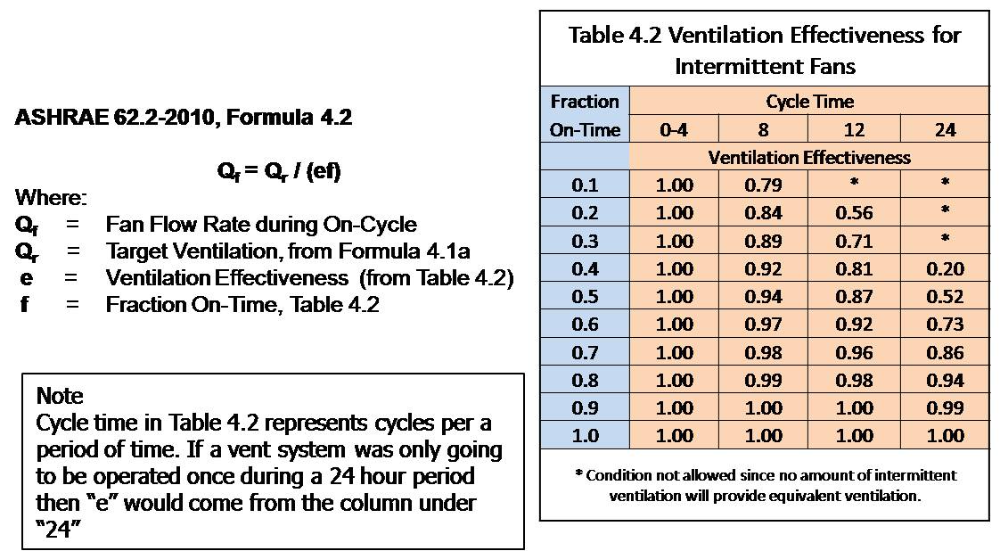
Considering that we want the fan to run at least once in a four-hour period, our Ventilation Effectiveness (e) is 1.0 (see Table 4.2, which shows 1.0 for a cycle time of 0-4 meaning that the fan would run at least once in each four-hour period or six times in a day. Also, the designer has determined that the Fraction On-Time will be 0.5 or 50% of the time. So to calculate the required fan airflow (Qf) to meet the target ventilation rate (Qr) based on an intermittent run time, the calculation would look like this:
Qf =  Qr / (ef)

Qf = 50 CFM / (1.0 x 0.5)

Qf = 50 / 0.5

100 = 50 / 0.5
So, 100 CFM is the size of the fan that is required if we are going to run the fan at least once every four hours for 50% of the time to meet the target ventilation rate. The fan could be set with a controller on any timer schedule that would meet the 50% run time, for example, 10 minutes on-10 minutes off, or 30 minutes per hour, etc.
Ensuring Success
A whole-house ventilation system should be installed in all new homes. The system should be commissioned after installation to verify that it works as planned. The system should be controlled to operate continuously or intermittently to provide desired or code-required ventilation rates. Humidity sensors and indoor air quality sensors that trigger additional ventilation levels to respond to conditions within the home are recommended. The energy rater will verify that the installed ventilation system meets code requirements and matches the whole-house mechanical ventilation design specified in the ENERGY STAR HVAC Design Report, if ENERGY STAR certification is sought.
Region
Supplemental dehumidification is often necessary for dwellings in humid climates, e.g., IECC Climate Zones 1A, 2A, and 3A.
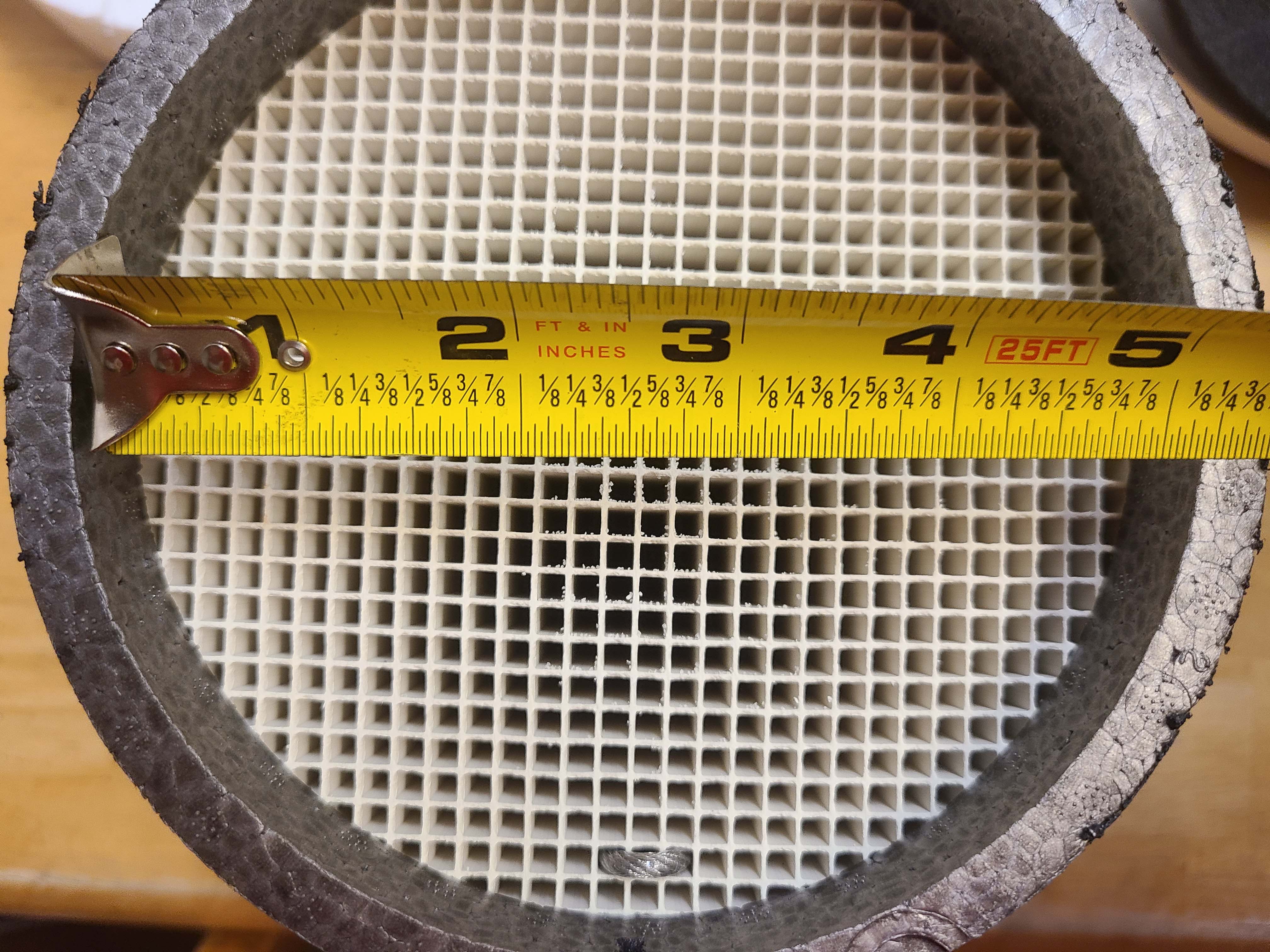
For whole-house ventilation systems that use outdoor air intakes, the intake grille should be covered with ≤ 0.5-inch mesh screen to keep out rodents and birds and should be located in an accessible place for maintenance, which includes cleaning to remove debris. Sensors and controls that trigger closure of outdoor air intakes during periods of high humidity are recommended in very humid climates. Similarly, sensors and controls that automatically trigger closure of outdoor air intakes or enable manual closure during periods of poor outdoor air quality, for example, if wildfires are occurring nearby, are also recommended.
Training
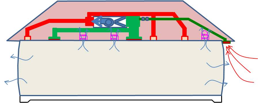
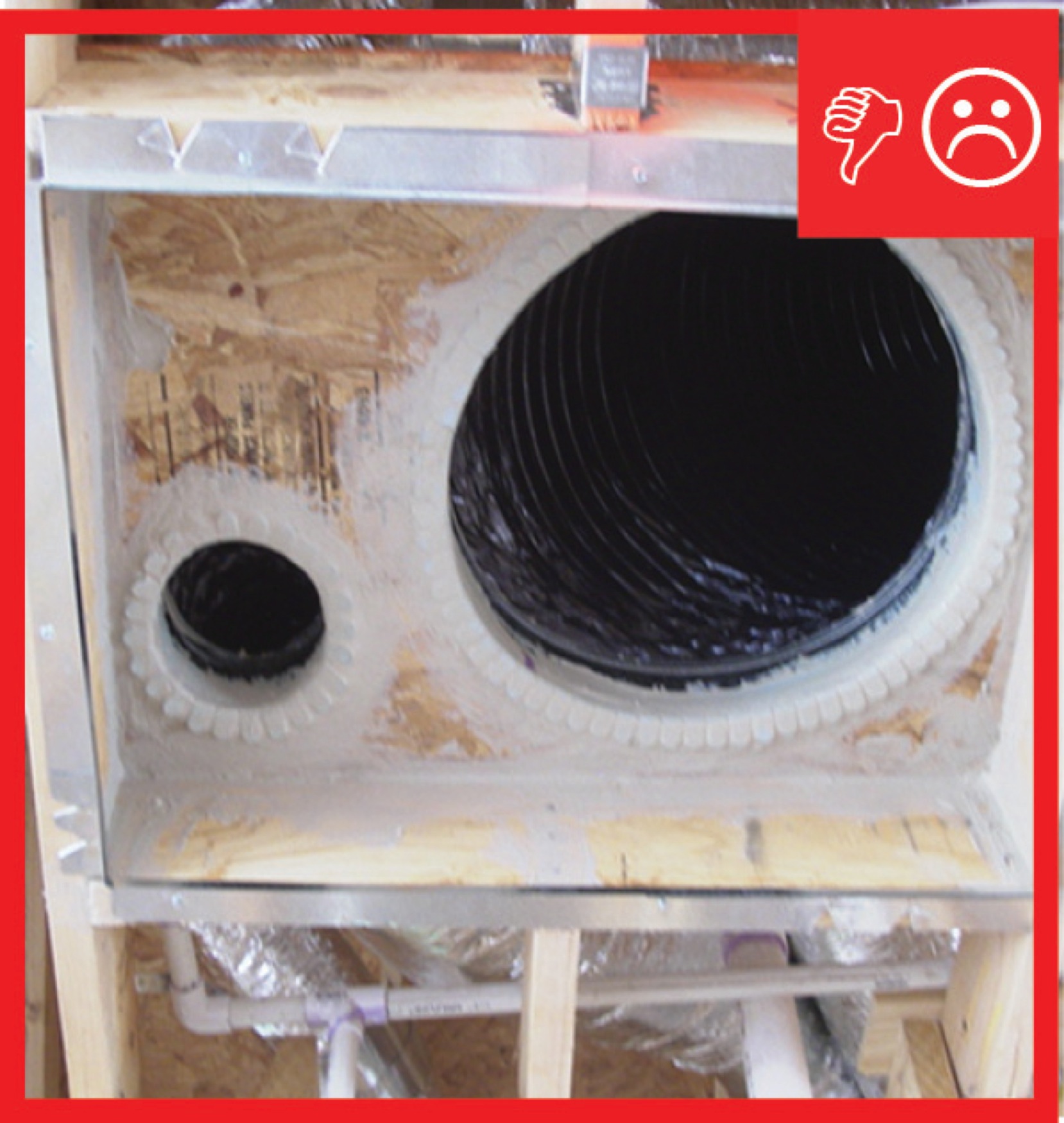
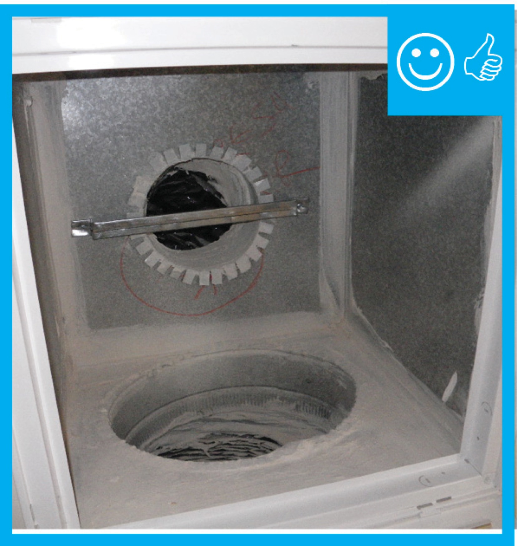
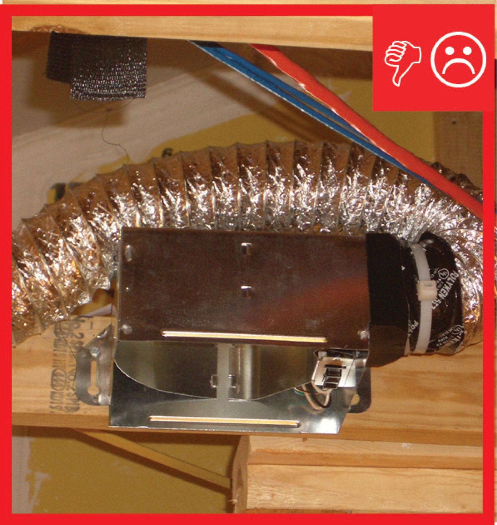
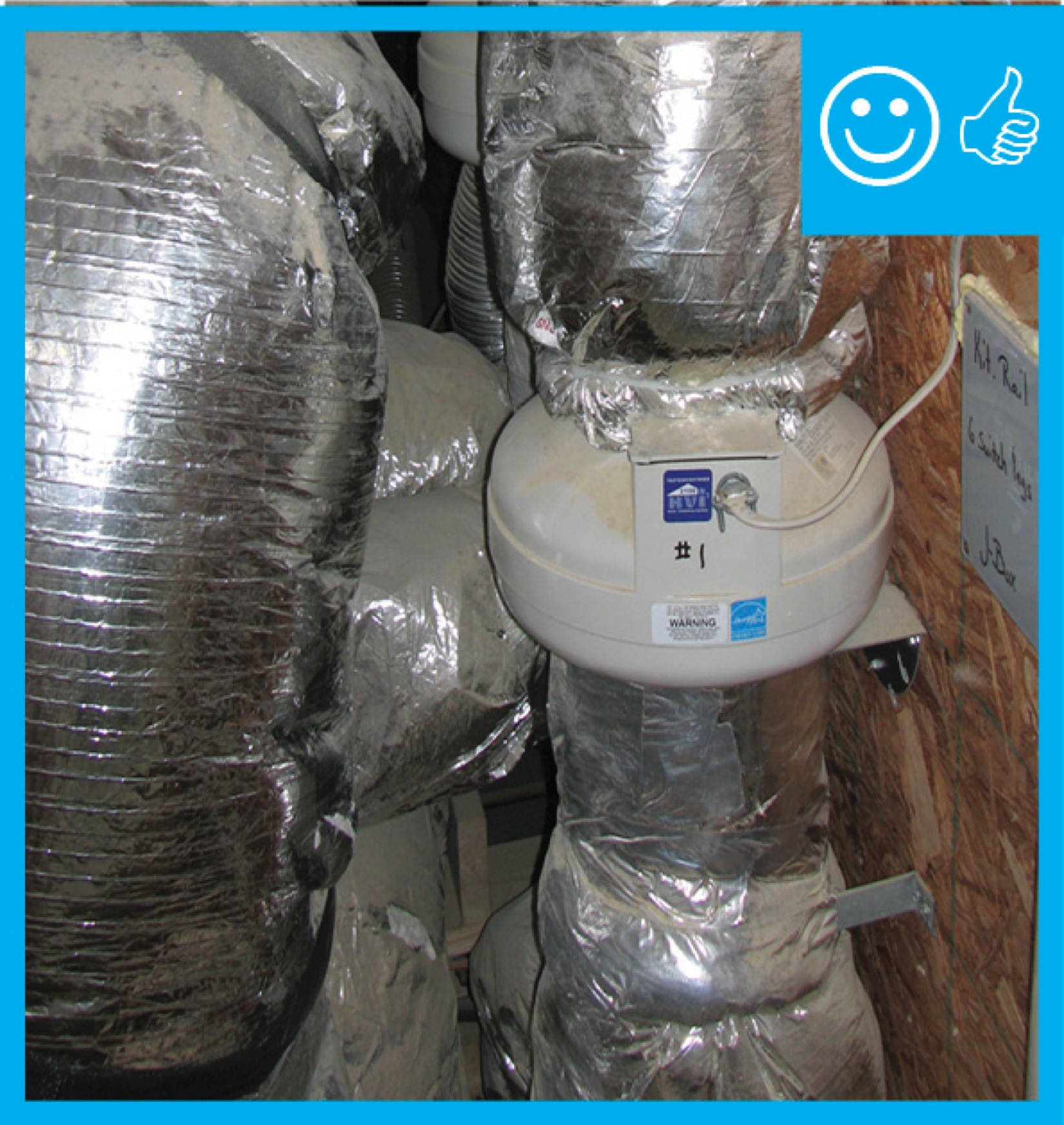
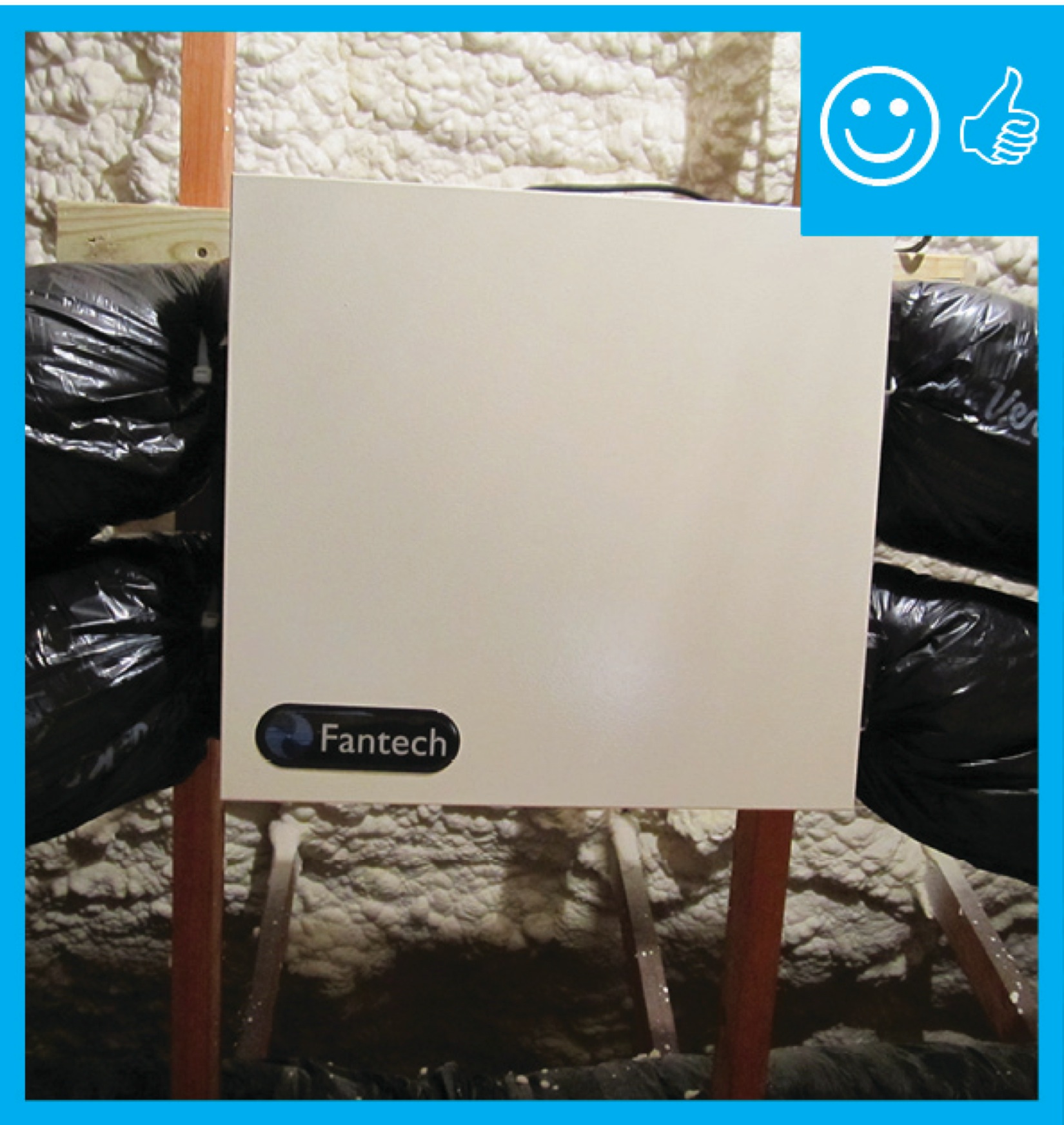
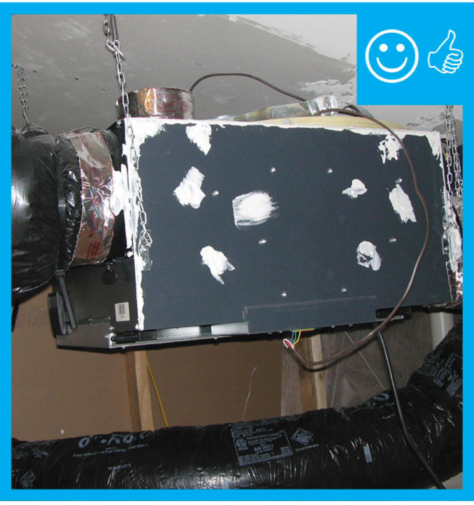
Right and Wrong Images
Source
Source
Source

Source
Source
Source
Source
Source
Source
Source

Source
Source

Source

Source
Source
Source
Source
Source
Source
Source
Source
Source
Source
Source

Source
Source
Presentations


Videos


Compliance
ENERGY STAR New Homes and Apartments
International Energy Conservation Code (IECC)
International Residential Code (IRC)
Associated Air Balance Council (AABC) National Standards for Total System Balance
National Environmental Balancing Bureau (NEBB) Section 15990
American Society of Heating, Refrigeration and Air-Conditioning Engineers (ASHRAE) Standard 62.2
Retrofit
SCOPE
If the existing home has no whole-house ventilation system, then install one of the options described in the Description tab - exhaust, supply or balanced ventilation.
For more on ventilation, see the U.S. Department of Energy’s Standard Work Specifications.
DESCRIPTION
(The following is excerpted from the ASHRAE Residential Indoor Air Quality Guide (Schoen et al. 2018).)
ASHRAE Standard 62.2 applies to all dwelling units, unlike the I-codes, which usually apply only to new dwellings and to existing dwellings undergoing substantial renovation. The ASHRAE standard is frequently applied to dwellings and other dwelling units that are undergoing weatherization, and it should be considered an important strategy for optimizing IAQ in any dwelling. Because existing dwellings are often less airtight than new ones, a best practice is to arrange for a blower door test (Strategy 1.4) on the dwelling so that the ASHRAE Standard 62.2 ventilation rate can be reduced based on infiltration. Doing so also provides the opportunity to identify and air seal large sources of leakage in the building enclosure.
Some people believe that it is better not to air seal an existing dwelling to avoid the need for mechanical ventilation. The consensus among building science and air quality experts is that a tightly sealed dwelling with a properly designed and operated mechanical ventilation system is always the best choice. In addition to the large differences in infiltration in extreme versus mild weather, existing dwellings are more likely than new ones to receive contaminated infiltration air from attached spaces, such as attics, crawlspaces, and garages.
For an extensive discussion of ventilation in existing guides, see the Solution Center guide Whole House Ventilation Strategies for Existing Homes.
See the Building America report Selecting Ventilation Systems for Existing Homes for more discussion on the distribution of outdoor air in existing homes.
COMPLIANCE
See Compliance tab.
More Info
Case Studies
References and Resources
*For non-dated media, such as websites, the date listed is the date accessed.
Contributors to this Guide
The following authors and organizations contributed to the content in this Guide.
Building Science Corporation, lead for the Building Science Consortium (BSC), a DOE Building America Research Team
Calcs-Plus
Pacific Northwest National Laboratory
U.S. Environmental Protection Agency
Sales
Balanced Ventilation = Fresh Air Balanced System
Technical Description
Fresh air balanced systems supply and filter outdoor air while exhausting an equal amount of indoor air. This type of system maintains a neutral balance in air pressure that minimizes moisture risks and optimizes mixing. These systems are often equipped with heat and moisture exchangers that optimize efficiency and comfort. This is achieved by exchanging heat and moisture between the incoming and outgoing air streams. This captures heat before it leaves the home in winter, heat before it enters the home in summer, moisture before it enters the home in summer, and moisture before it leaves the home in winter.
Questions? Comments? Contact our webmaster.