

Scope
Install taped insulating sheathing to serve as the drainage plane to keep water out of the wall cavity and to direct water down and away from the wall.
- Integrate the insulating sheathing drainage plane with any flashing installed around doors, windows, and wall penetrations and any flashing installed at the top or base of walls.
- Use extruded polystyrene (XPS) or foil-faced polyisocyanurate insulation following the manufacturer’s installation instructions.
- Thoroughly tape all seams in the insulation, using a manufacturer-recommended tape. Install the sheathing panels vertically to minimize horizontal seams as much as possible.
- Before taping seams, the foam surfaces must be clean and dry, seams should meet without large gaps, exterior temperature should be above 15°F. See the Success Tab for more information on related activities.
See the Compliance Tab for links to related codes and standards and voluntary federal energy-efficiency program requirements.
Description
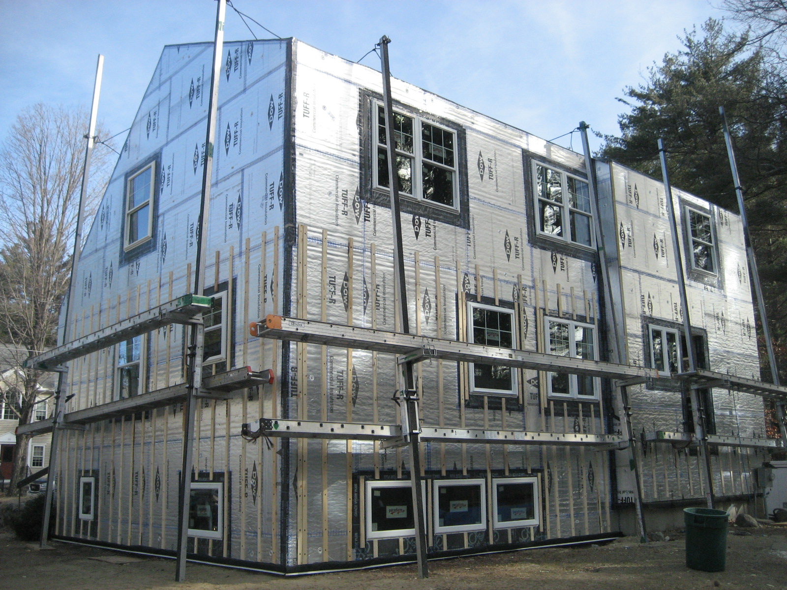
When rigid foam insulating sheathing is installed on the exterior walls of a home, the foam can serve as a drainage plane, taking the place of house wrap for time and cost savings. To serve as a drainage plane, the seams in the foam sheathing must be properly taped with sheathing and flashing tapes to provide continuity of the drainage plane at joints between panels. The tapes must be durable enough to prevent ingress of water at panel joints for the life of the system. Sheathing tapes and sometimes flashing tapes are also needed to integrate the top edge of diversion flashings (head flashings, flashings over penetrations, step flashings, kick-out flashings, etc.) with the drainage plane.
In addition to an effective drainage plane, a water control system also requires proper flashing at openings, penetrations, and connections to other assemblies. Note that this guide is not intended as a comprehensive reference for proper flashing methods. Rather, it addresses issues specific to the use of rigid foam insulation panels to create a drainage plane in an exterior wall system. Refer to other guides in the Building America Solution Center and the resources listed for specific flashing guidance. For more on weather-resistant barriers in wall assemblies, see the guide Drainage Plane Behind Exterior Wall Cladding. For more on rigid foam used as a continuous thermal barrier in wall systems, see the guide Continuous Rigid Insulation Sheathing/Siding. It is important to understand that a drainage plane or water control system is not the same thing as an air control (or air barrier) system. While components of the water control system might also serve as part of the air control system, the detailing for air control is different than detailing for water control. Air control detailing is not addressed in this guide.
Material Recommendations
Insulating sheathings used for a drainage plane must be approved for this application (check with the manufacturer). These insulating sheathings will have a smooth, non-capillary-active surface that is sturdy enough to allow application and repositioning of tapes. Many extruded polystyrene and foil-faced polyisocyanurate boards are approved for use as drainage planes. Some expanded polystyrene products are too porous to serve as a drainage plane. In order to effectively support implementation of a drainage plane, the insulating sheathing must be
- smooth or not significantly textured
- clean
- dust free
- warm (ideally).
A superior sheathing tape for use with an insulating sheathing drainage plane is
- acrylic adhesive-based
- available in wide widths up to 4 inches
- shown through jobsite experience to be able to adhere to almost any substrate with high reliability in a range of climatic situations
- a product with good temperature and UV resistance
- available nationwide at a competitive price.
Although foil-faced insulating sheathings can serve as a drainage plane, foil tapes are not recommended as these tend to rip easily and are more prone to wrinkling or creasing during installation. Over time, foil tapes can have the tendency to "walk-off" their substrates due to differential thermal expansion.
A superior flashing tape is
- butyl adhesive-based
- not more than 20 mil thick (ensures overlaps do not build up too much thickness)
- available in 6- to 9-inch widths
- backed with a facer that is very expansion/contraction compatible with its adhesive substrate
- backed with a facer that is no wider than the adhesive so it does not trap water
- shown through jobsite experience to be able to adhere to almost any substrate with high reliability in a range of climatic situations
- a product with good temperature and UV resistance
- available nationwide at a competitive price.
Some rubberized asphalt adhesives provide adequate adhesion on insulating sheathing; however, care must be taken to ensure compatibility with foam plastic substrates.
Flashing tape should not be confused with an ice and water protection membrane such as is typically used on roofs. Ice and water membranes typically do not adhere as well as flashing tapes or flashing membranes and also tend to have a thickness that causes excessive build up at overlaps.
General Implementation Recommendations
- Horizontal joints present a greater risk than vertical joints. Minimize the occurrence of horizontal joints as much as possible.
- Z-flashings should be used on any high-risk horizontal joint
- Where thicker tapes (20-30 mil) are installed horizontally, a termination strip of thin tape should always be used over the top edge of the thicker tape.
- On horizontal joints, the tape should be offset favoring more tape and hence more adherence to the upper sheet of substrate. In general 2/3 of the tape should be on the top sheet and the remainder lapped over the bottom sheet.
- The top edge of the thin tape must have full contact with the substrate without “fish mouths,” wrinkles, or interruptions by fasteners.
- Vertical joints should be taped with a minimum 3” wide acrylic tape and gravity lapped with the horizontal joint.
High-risk horizontal joints are those that are subject to significant incident rain (or other liquid water) and pressure. For example, the horizontal joints on the windward side of a house on the ocean in a wet climate (greater than 40 inches average rainfall per year) would be high-risk.
A termination strip is needed at the top edge of horizontal thick butyl-adhesive tapes or membranes because the thicker profile can hold water and because, over time, the different thermal expansion between the adhesive layer and the backing can cause thicker tapes to curl away from the substrate at the edges. Caulk could also be used to terminate this horizontal edge but a tape termination strip is simpler to implement properly and completely.
If the insulating sheathing is installed directly over the framing:
- Backup wood blocking should be installed behind horizontal joint locations to provide a backup and stiffness, allow the perimeter of the sheet to be fastened properly, and provide support for when the tape is installed
- Vertical joints should land on framing members.
Construction Sequencing Details
The construction sequencing details below show installation of an insulating sheathing drainage plane on a wall. Job supervisors must be able to identify proper materials and be familiar with proper implementation techniques. Job supervisors must also make sure that construction crews understand proper implementation techniques.
The construction sequences below demonstrate three recommended methods to effectively seal the joints in exterior insulating sheathing to create a simple, long-term, and durable drainage plane. The three methods are designated GOOD, BETTER, and BEST as follows:
GOOD – The basic exterior insulation drainage plane uses 3- or 4-inch-wide acrylic tape to cover joints in the insulating sheathing.
BETTER – The improved exterior insulation drainage plane uses 4- to 6-inch-wide butyl tape with 2-inch-wide acrylic termination tape at horizontal joints. This approach combines an aggressive adhesive with the advantage of a self-sealing membrane.
BEST – This approach improves on the “BETTER” approach by using a butyl z-flashing at horizontal panel joints to protect the assembly from liquid water that may be at the back of the panel joints.
The progression from GOOD to BETTER to BEST represents increasing protection against water ingress as well as greater tolerance for installation imperfections.
The sequencing details show installation of insulating sheathing directly over framing. The sequences can be easily adapted to installation over structural sheathing. In most cases, horizontal blocking is not needed behind joints in the exterior insulation where the exterior insulation is installed over structural sheathing.
How to Install a Drainage Plane using Rigid Foam Insulation - GOOD – Basic Exterior Insulation Drainage Plane – 3- or 4-inch-wide acrylic tape
Install framing in the exterior wall and include blocking for attaching the rigid foam. See Figure 1.
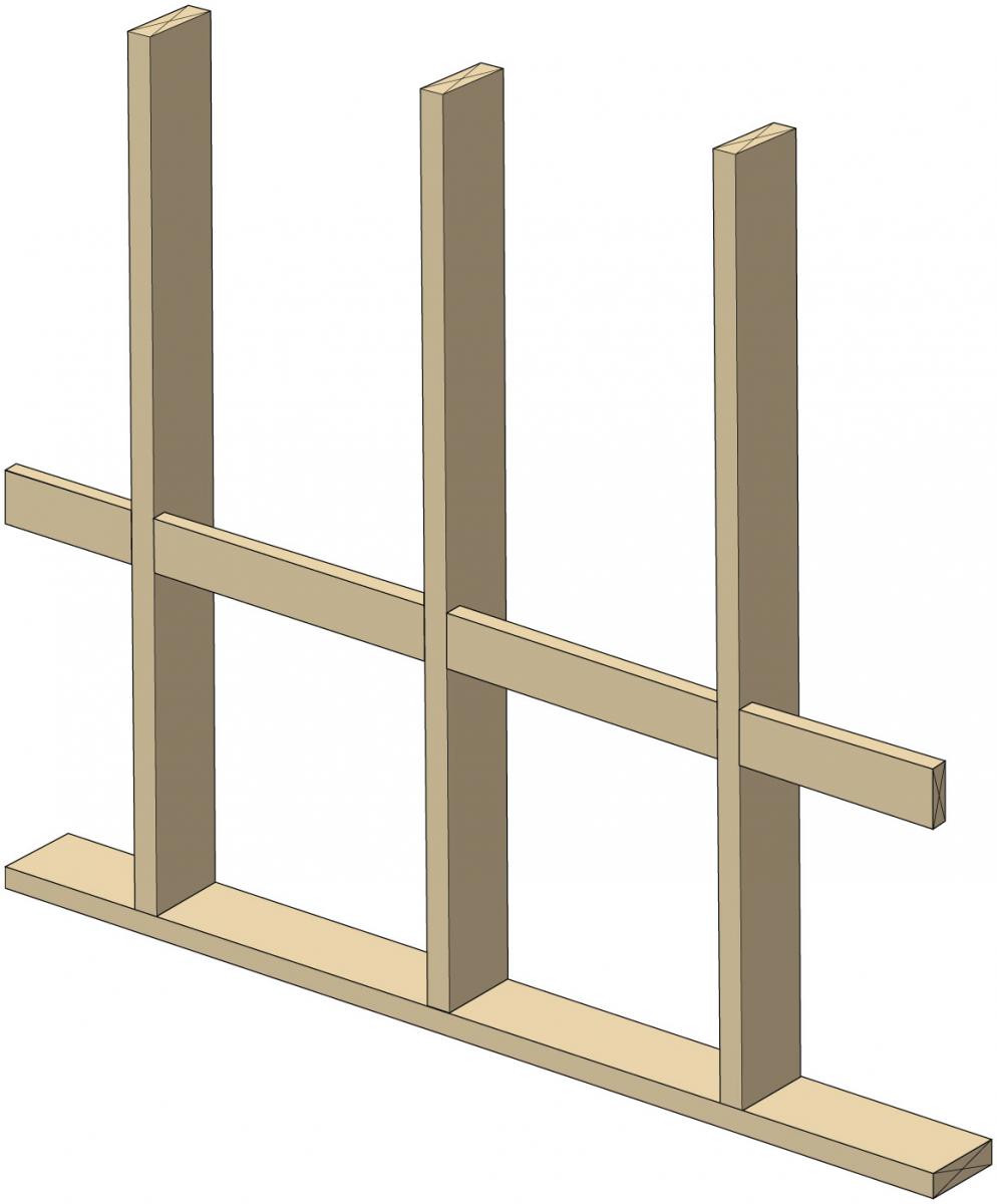
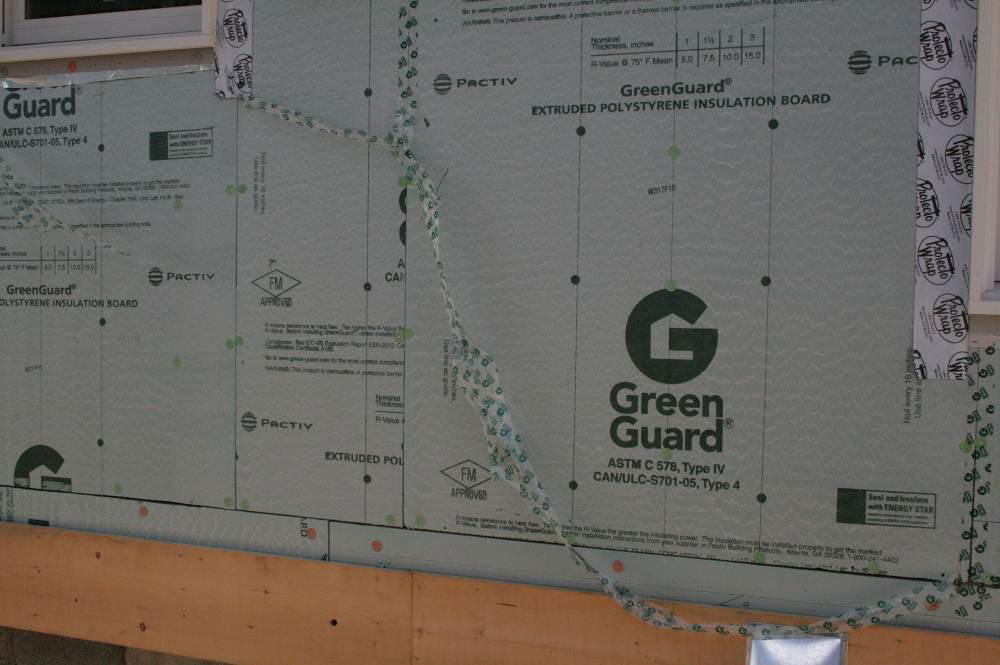
Figure 1. Construct an exterior framed wall and install blocking for attaching rigid foam sheathing. (Source: Grin and Lstiburek 2014.) Install rigid foam sheathing on the exterior wall. Use the fasteners and fastener schedule recommended by the manufacturer. To minimize holes in the foam, do not overdrive fasteners. See Figure 2.
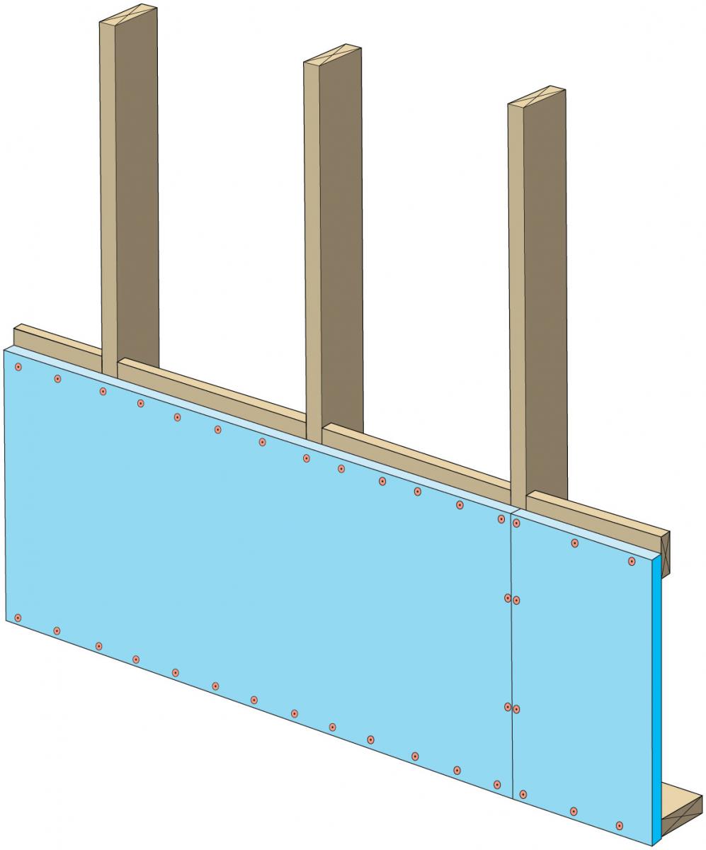
Figure 2. Install rigid foam insulation sheathing on the exterior walls per manufacturer's instructions. (Source: Grin and Lstiburek 2014.) - Wipe down foam panels along seams to remove dust and debris.
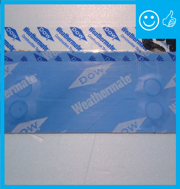
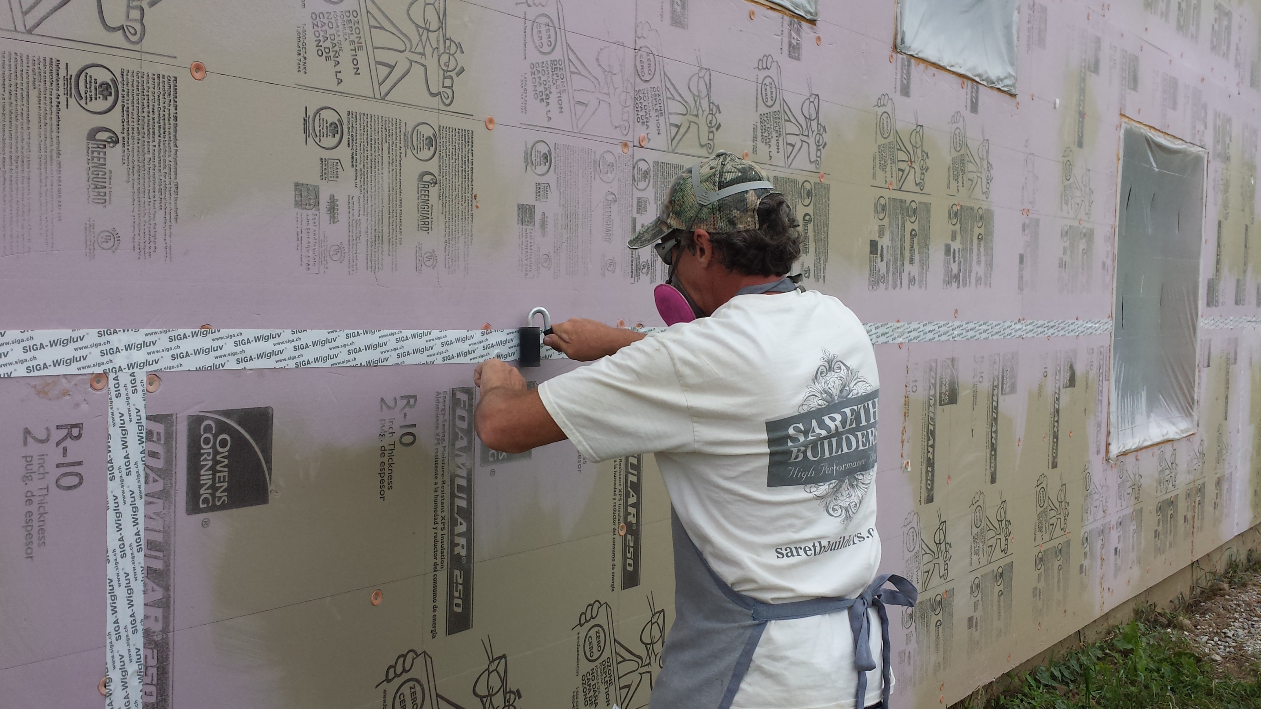
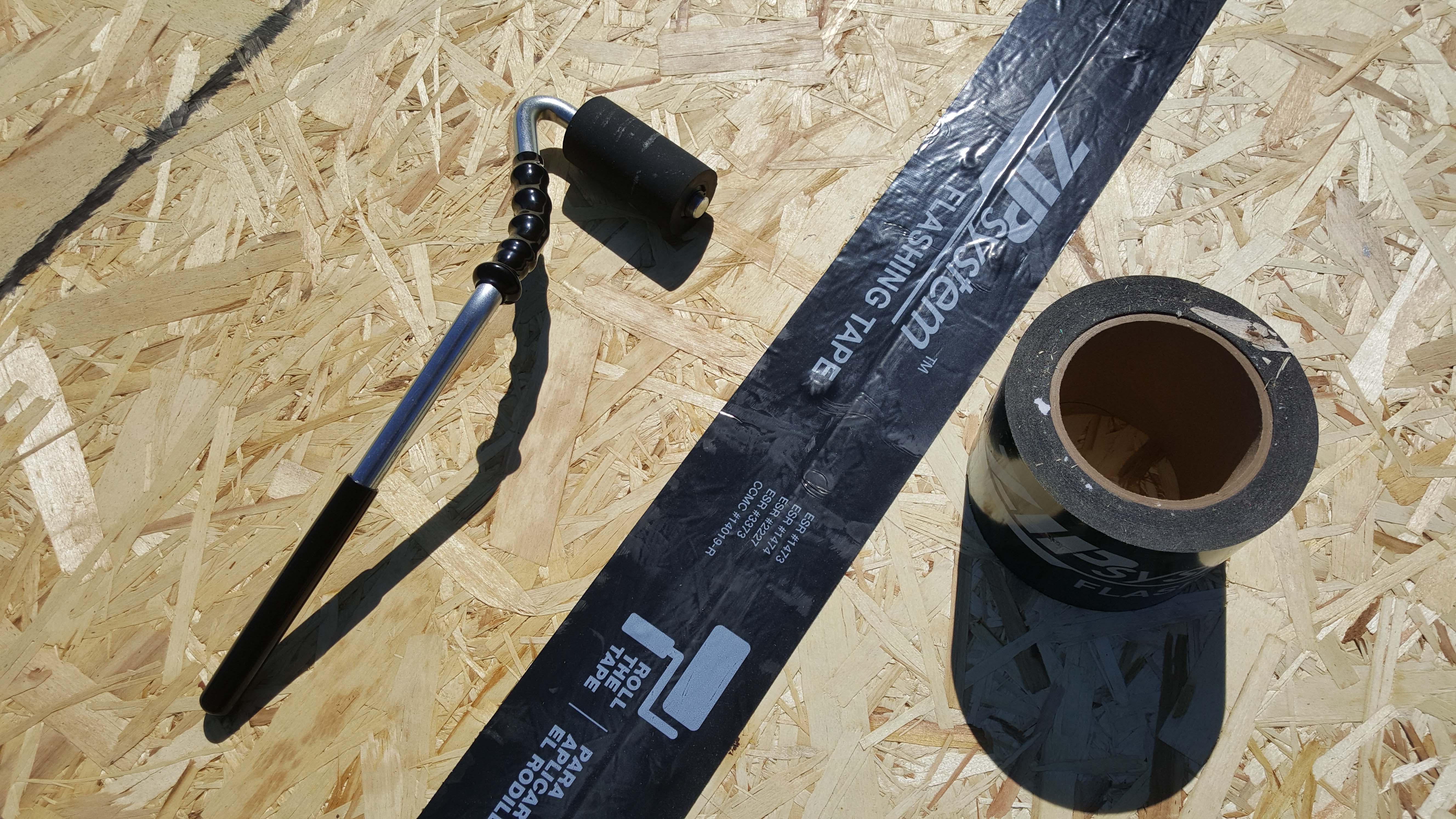
Install tape along all vertical seams. Press firmly or use roller to ensure a strong adhesion. See Figure 3.
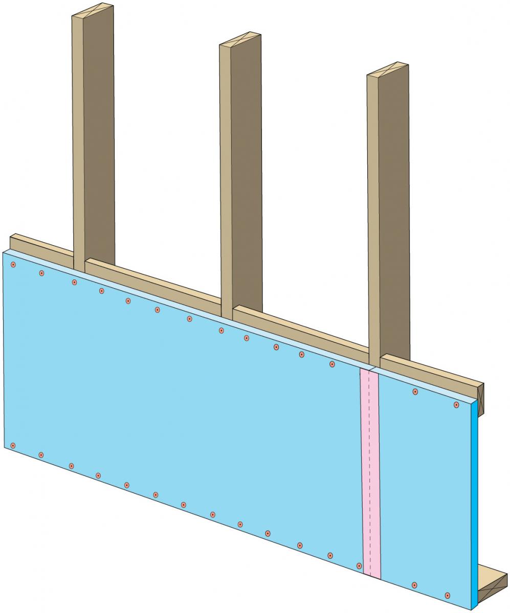
Figure 3. Tape vertical seams in rigid foam sheathing and press firmly to ensure adhesion. (Source: Grin and Lstiburek 2014.) Install upper insulation panels per manufacturer's instructions. See Figure 4.
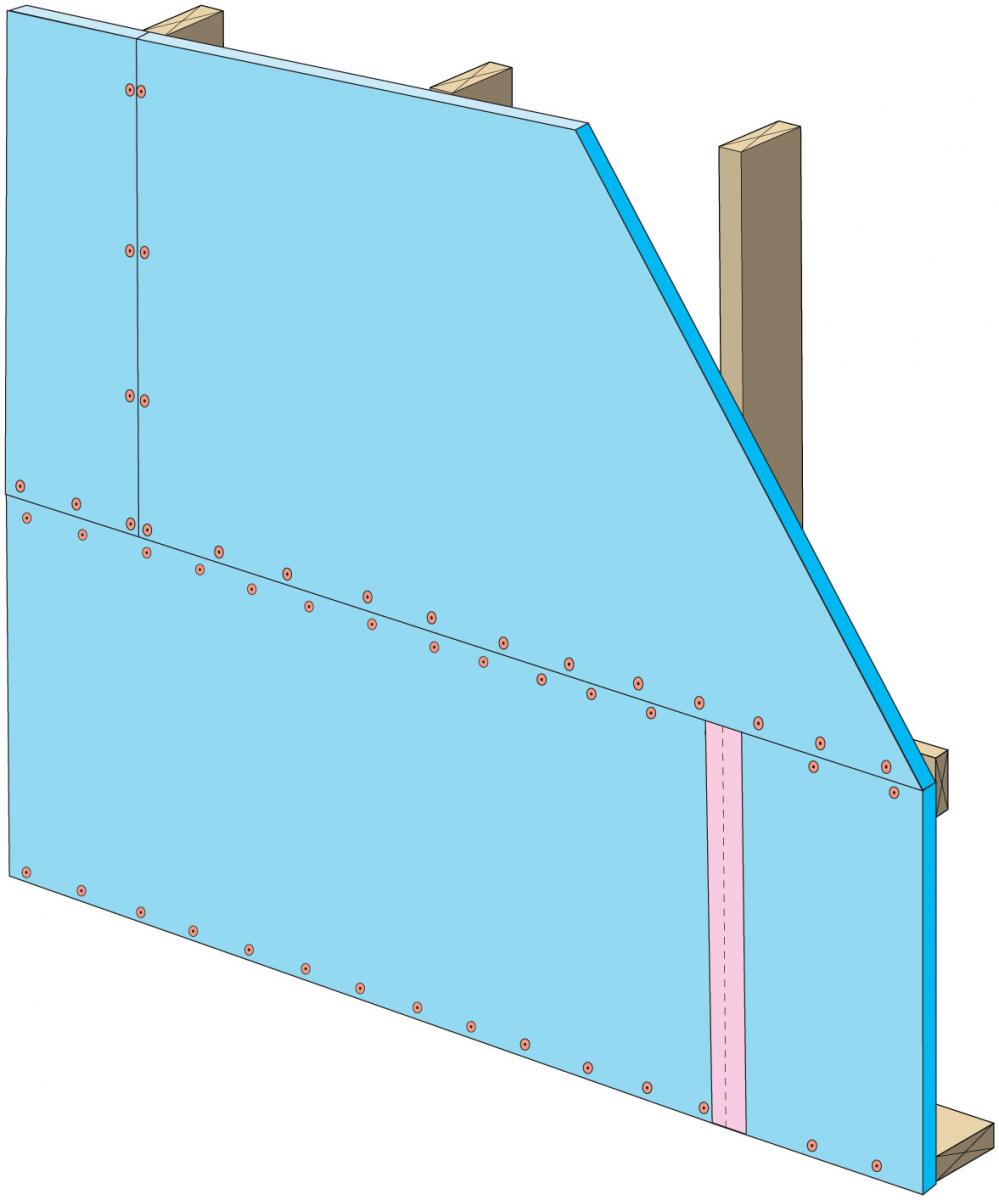
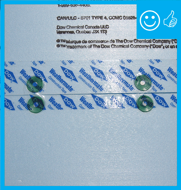
Figure 4. Install upper foam insulation panels per manufacturer's instructions. (Source: Building Science Corporation.) Clean foam along seams and tape horizontal joints with minimum 3" wide tape placing tape offset so that 2/3 of the tape is on the upper panel and 1/3 extends onto the lower panel, with the tape covering the fasteners if possible. The top edge of the tape must adhere continuously to the upper sheet without wrinkles, fish mouths, or interruptions by fasteners. Press or roller tape firmly to ensure adhesion. See Figure 5.
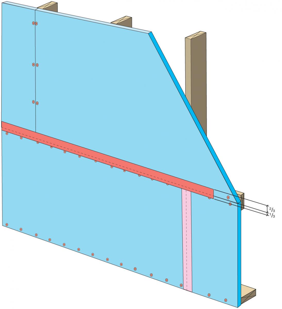
Figure 5. Tape horizontal joints in rigid foam sheathing with tape that is at least 3" wide and offset so that 2/3 of the tape is on the upper panel and 1/3 is on the lower panel. (Source: Grin and Lstiburek 2014.) Clean foam board along vertical seams and tape the seams. Press or roller firmly to ensure adhesion. See Figure 6.
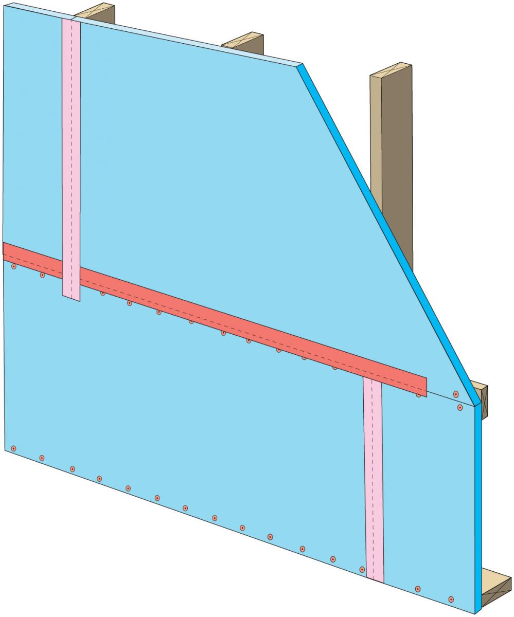
Figure 6. Install tape on vertical joints of upper foam panels insulation, pressing firmly to ensure adhesion. (Source: Grin and Lstiburek 2014.) - Install flashing around windows and door openings and install flashing at all penetrations through the drainage plane. See the guides Fully Flashed Window and Door Openings; Flashing at Bottom of Exterior Walls; and the fact sheet Weather Resistive Barriers.
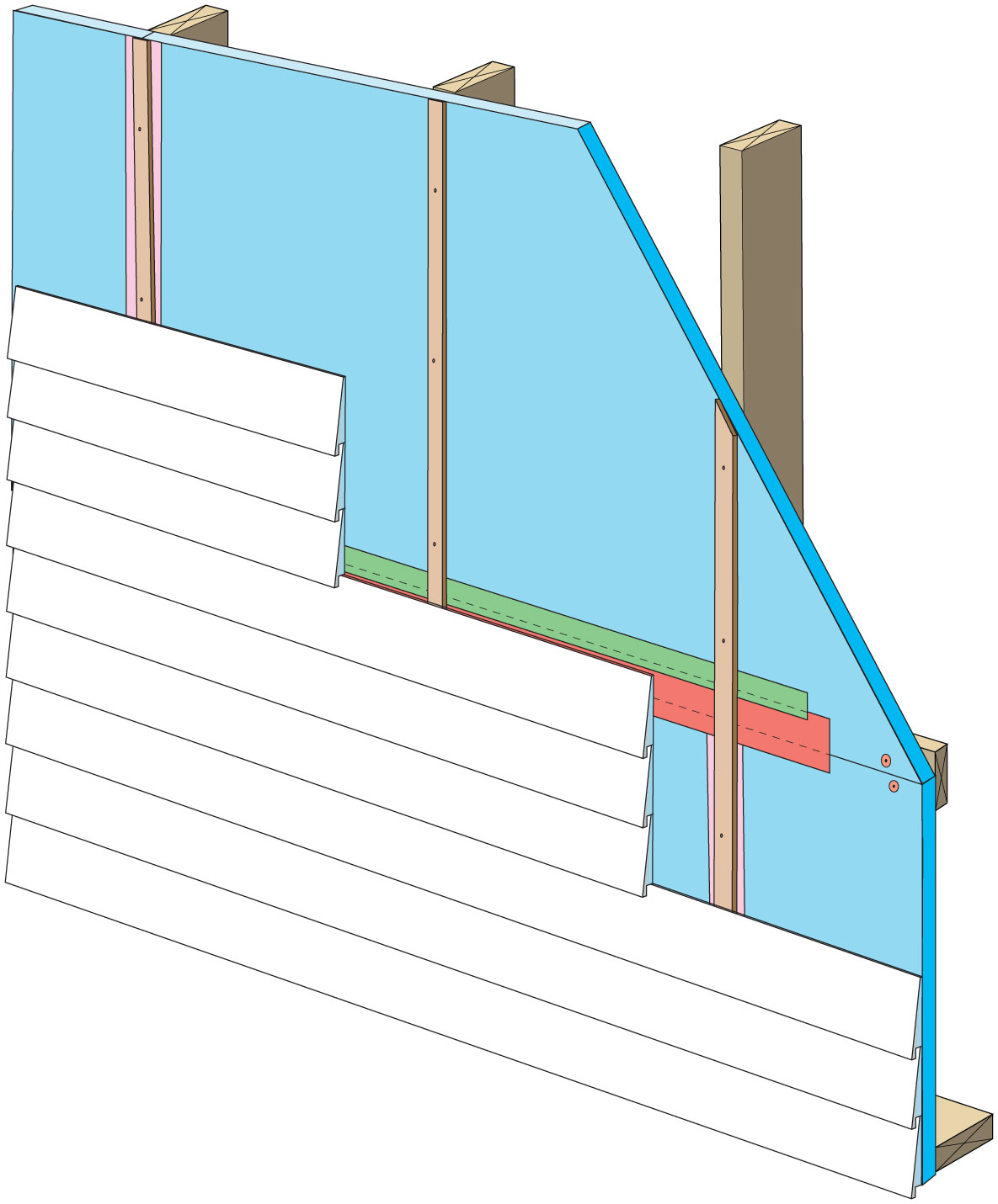
Install rain screen material or provide an air gap behind the cladding. For wood or fiber cement siding this can be accomplished by installing furring strips over the foam as shown in Figure 7. These furring strips also provide a secure fastening surface for the siding. Install insect screening. For more information about installing rain screens and ventilation gaps behind cladding, insect screening with furring strips, weep screeds for stucco siding, and weep holes in brick, see the guides Flashing at Bottom of Exterior Walls and Drainage Plane behind Exterior Wall Cladding.

Figure 7. Exterior cladding is installed over furring strips installed over rigid foam sheathing. (Source: Grin and Lstiburek 2014.)
How to Install a Drainage Plane using Rigid Foam Insulation - BETTER – Improved Exterior Insulation Drainage Plane – 4” – 6” wide butyl tape with 2” wide acrylic termination tape
Follow the first four steps described above for the "Good" installation: Frame the wall, install horizontal blocking where joints in the exterior insulation will exist, install lower insulation per manufacturer's recommendations and tape vertical seams, install upper insulation per manufacturers' instructions and tape horizontal seams as shown in Figure 8.
Figure 8. Tape horizontal joints in rigid foam sheathing with 4-inch-wide butyl tape placing tape offset with 2/3 of the tape above the joint and 1/3 of the tape below the joint. (Source: Grin and Lstiburek 2014.) Add a second layer of 2-inch-wide tape, offsetting the tape so that 2/3 is above the edge of the 4-inch tape and is adhered directly to the insulation. Press or roller firmly to ensure adhesion. See Figure 9.
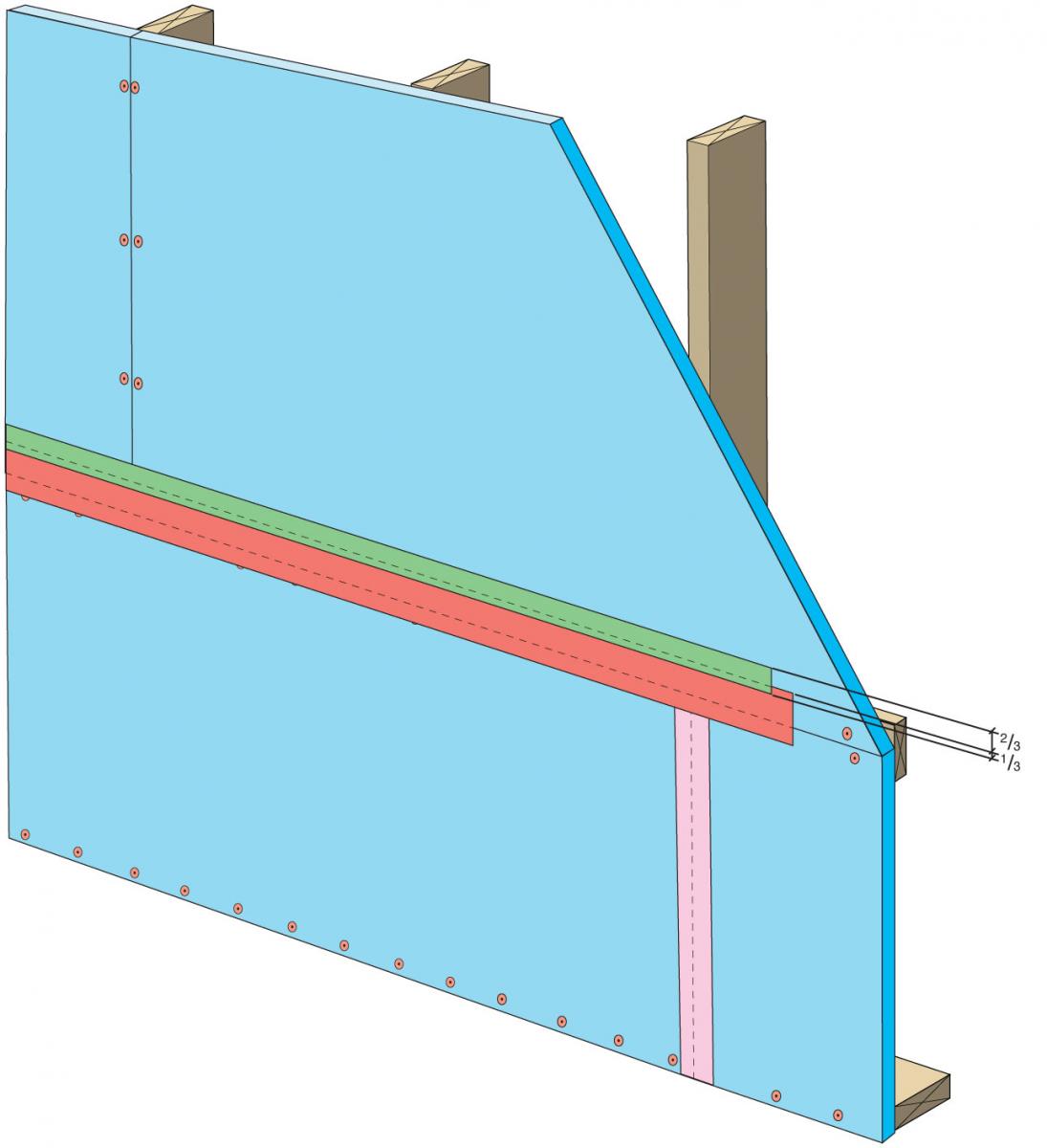
Figure 9. For better sealing of foam sheathing joints, install 2-inch tape over the top edge of the 4-inch tape with the tape offset so that 2/3 of the 2-inch tape is adhered to the insulation. (Source: Grin and Lstiburek 2014.) Clean the foam along the vertical joints and install 3-inch tape on the vertical joints of upper insulation panels overlapping the horizontal joints. Press or roller the tape firmly to ensure adhesion. See Figure 10.
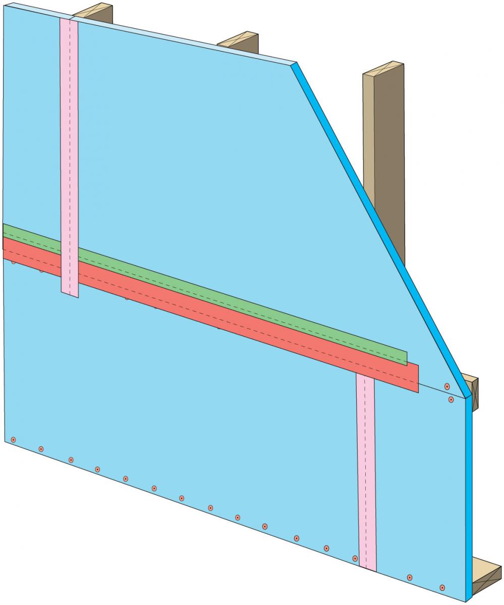
Figure 10. Seal the vertical joints in the rigid foam sheathing with 3-inch tape that extends down to overlap horizontal joints. (Source: Grin and Lstiburek 2014.) - Install flashing, rain screen, and exterior cladding as described in Steps 8 and 9 above.
How to Install a Drainage Plane using Rigid Foam Insulation - BEST – Z-Flashed Exterior Insulation Drainage Plane – Butyl z-flashing with 2-inch-wide acrylic termination tape
- Follow the first three steps described above for the "Good" installation: Frame the wall, install horizontal blocking where joints in the exterior insulation will exist, install lower insulation per manufacturer's recommendations and tape vertical seams.
Install self-adhered butyl Z-flashing that is at least 6 inches wide. See Figure 11.
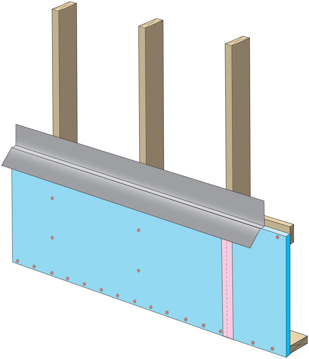
Figure 11. For the best water management seam detail, install a 6-inch-wide self-adhered butyl Z-flashing between the horizontal panels of rigid foam sheathing. (Source: Grin and Lstiburek 2014.) Install upper insulation panels over the top portion of the flashing. Fasten the panel using the fasteners and fastener schedule recommended by the manufacturer. Take care not to overdrive the fasteners. See Figure 12.
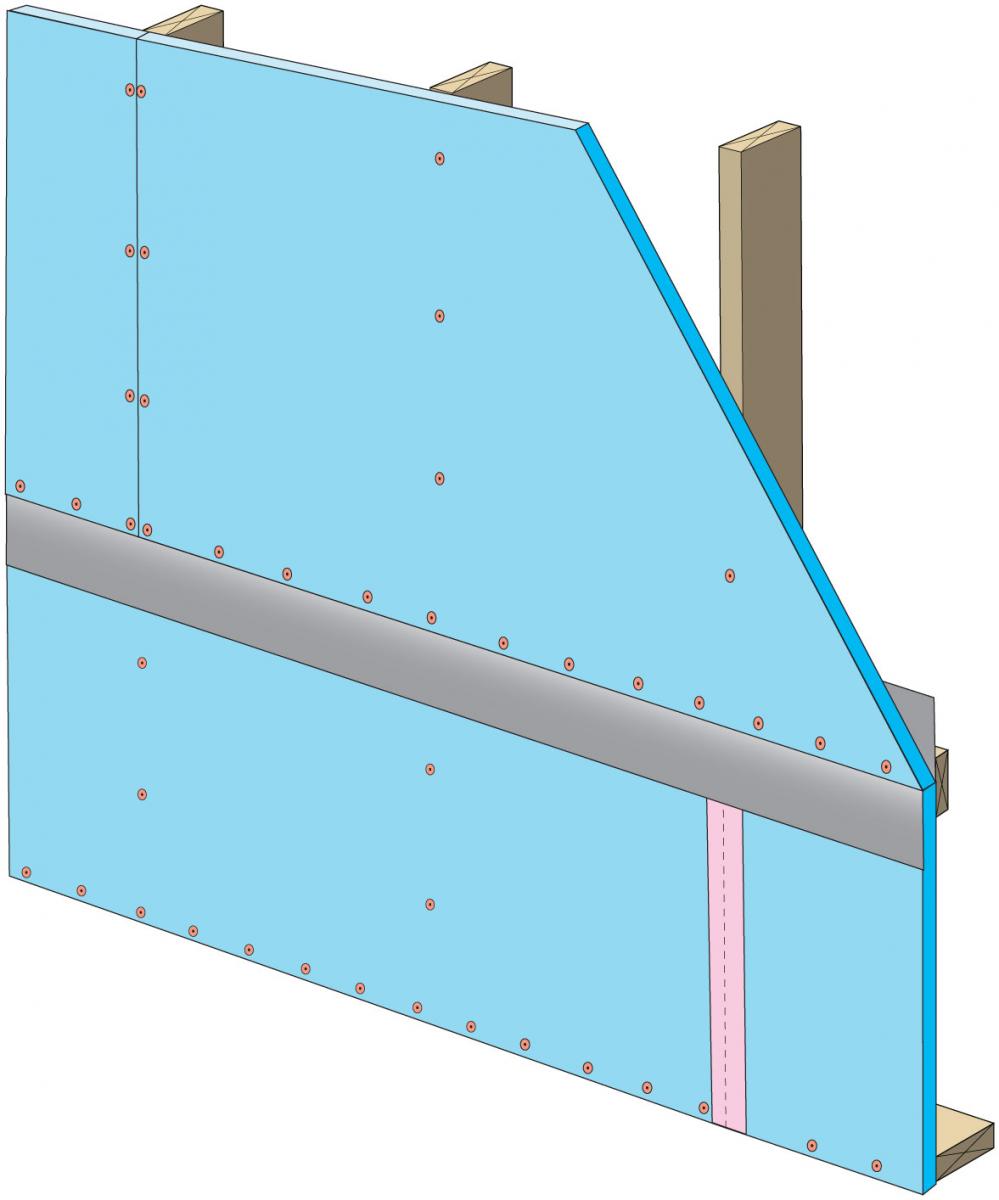
Figure 12. Install upper foam insulation sheathing over the self-adhered butyl Z-flashing. (Source: Grin and Lstiburek 2014.) Clean the foam along the horizontal seams and install 2-inch tape above and below the Z flashing to improve air sealing. Press firmly to ensure adhesion. See Figure 13.
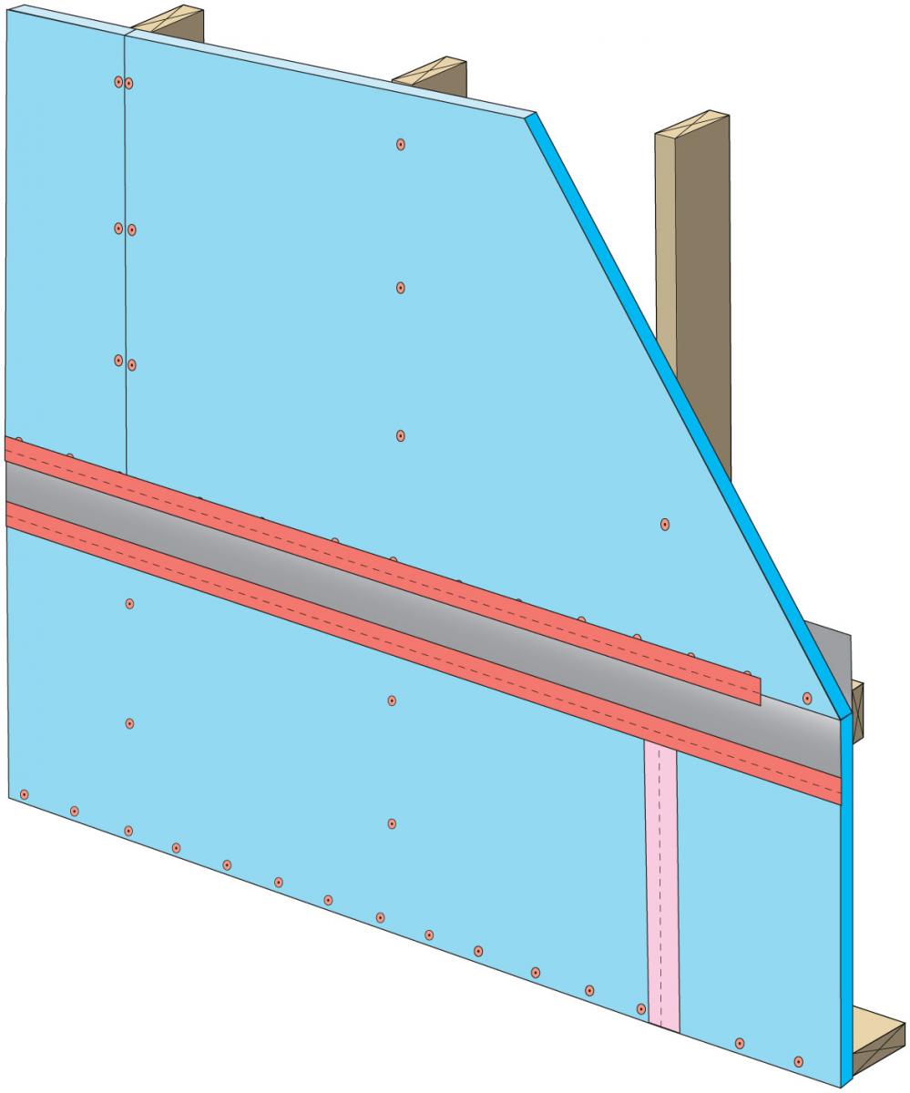
Figure 13. Use 2-inch tape to air seal the joint above and below the self-adhered butyl Z-flashing in the horizontal joint of the rigid foam sheathing. (Source: Grin and Lstiburek 2014.) Clean foam surfaces along the vertical seams and install 3" tape to seal the joints and overlap the horizontal tape. Press tape firmly to ensure adhesion. See Figure 14.
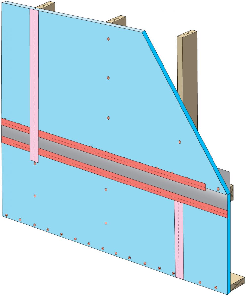
Figure 14. Install 3-inch tape on vertical joints of rigid foam insulation overlapping the horizontal joints. (Source: Grin and Lstiburek 2014.) - Install flashing, rain screen, and exterior cladding as described in Steps 8 and 9 of the "Good" installation instructions above.
Ensuring Success
Do Not Proceed if:
- Surfaces are wet or icy
- Exterior temperature is below 15°F
- Insulating sheathing is not XPS or foil-faced polyisocyanurate specifically approved for use as a weather-resistive barrier.
Clean surfaces that are dusty or dirty prior to taping.
Verify that insulation panels fit together snuggly with no large gaps in the insulation layer.
In addition to the seam-sealing steps described in this guide, follow the flashing recommendations described in these guides to ensure a continuous drainage plane: Fully Flashed Window and Door Openings; Flashing at Bottom of Exterior Walls; and Drainage Plane Behind Exterior Wall Cladding.
Interviews with builders implementing taped insulating sheathing drainage planes have yielded the following recommendations regarding making taped insulating sheathing a simple, long-term, and durable drainage plane:
- Horizontal joints should be limited or eliminated wherever possible
- Where horizontal joints do exist, special attention to methods and materials is needed
- Frequent installation inspection and regular trade training are required to maintain proper installation.
Region
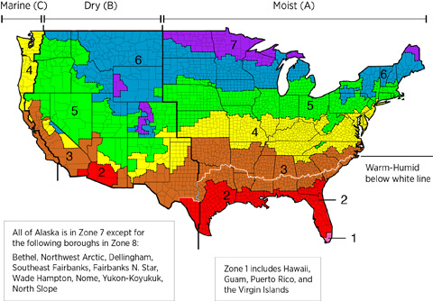
The exterior wall assembly should be designed for the specific hygrothermal region, rain exposure zone, and interior climate where the home is located.
The map in Figure 1 shows the climate zones for states that have adopted energy codes equivalent to the International Energy Conservation Code (IECC) 2009, 12, 15, and 18. The map in Figure 2 shows the climate zones for states that have adopted energy codes equivalent to the IECC 2021. Climate zone-specific requirements specified in the IECC are shown in the Compliance Tab of this guide.

The insulation levels should be based on the minimum requirements for vapor control in the current adopted building code and the minimum requirements for thermal control in the current energy code. Additional insulation can be added above these minimums to create high R-value exterior wall assemblies. The minimum insulation requirements for ceilings, walls, floors, and foundations in new homes, as listed in the 2009, 2012, 2015, 2018, and 2021 IECC and IRC, can be found in this table.
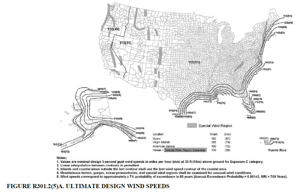
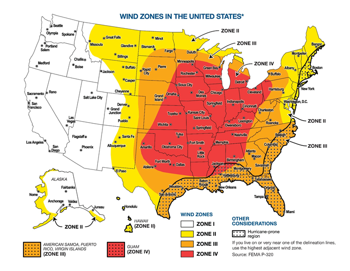
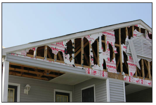
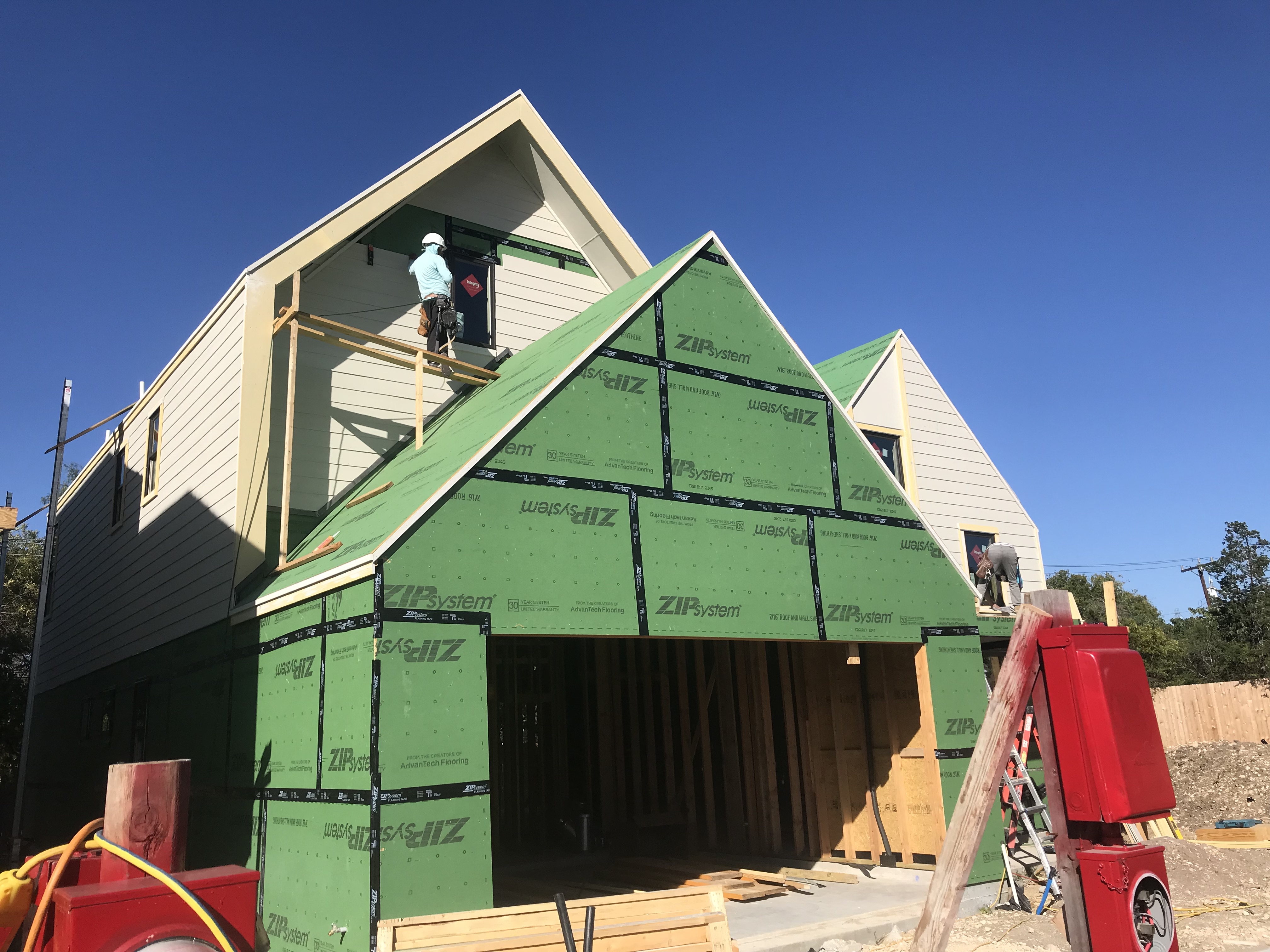
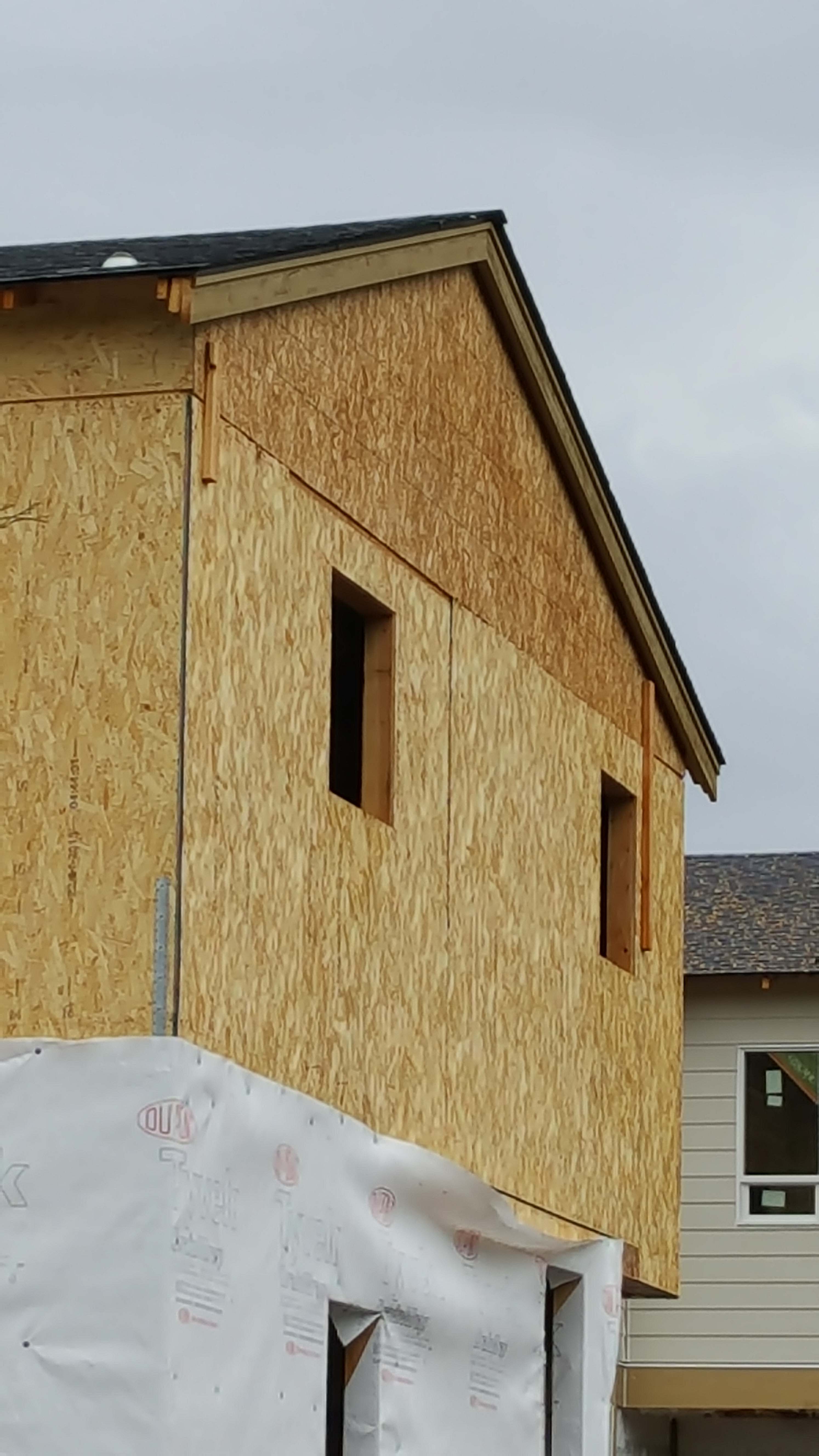
High Wind Zone: If your home is located in one of the designated high-wind zones shown in Figures 3 and 4, ensure that the siding is wind resistant to minimize the risk of damage to the rigid foam sheathing layer.
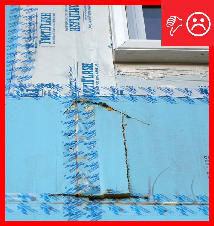
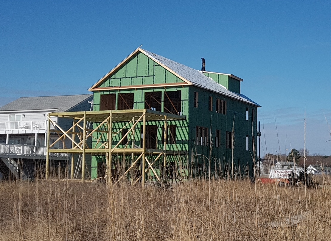
Rigid foam should not be used as the sole sheathing material in gable end walls in high-wind areas; it should be supported by plywood or OSB. In the house shown in FIgure 5, the vinyl siding at the gable end wall was installed over plastic foam insulation with no plywood or OSB wood sheathing behind it. The foam insulation and vinyl siding alone were not able to withstand wind pressures which caused the wall to fail allowing wind-driven rain to freely enter the attic and saturate the ceiling insulation, causing collapse of the ceiling.
Fire Safety - With limited exceptions, International Building Code Section 2603.5.5, Vertical and lateral fire propagation, requires wall assemblies in Type I, II, III and IV construction using foam plastic insulation to pass the National Fire Protection Association (NFPA) 285 testing requirements. Despite stating “non-load bearing” in its title and scope, NFPA 285 applies to both non-load bearing and load-bearing walls. There are many polyiso, EPS, and XPS rigid foam products that have passed the NFPA 285 wall assembly test for fire resistance; some fireproofing installation details may be required. Consult the manufacturers’ instructions (Walls & Ceilings 2017).
See the Solution Center guide Moisture-, Impact-, Fire-, and Pest-Resistant Exterior Siding for more information.
Training
Right and Wrong Images
Source
Measure Guideline research report providing simple, long term, and durable solutions when using tapes and flashing membranes in conjunction with the exterior face of rigid polymeric foam sheathing to create the drainage plane of a wall system.
Source
Measure Guideline research report providing simple, long term, and durable solutions when using tapes and flashing membranes in conjunction with the exterior face of rigid polymeric foam sheathing to create the drainage plane of a wall system.
Source
Source
Source
Report summarizing current research, summarizes issues that have been experienced with current best practices, and recommends ways in which the best practices can be improved for water managing sheathings.
Source
Source
Guide describing details that serve as a visual reference for each of the line items in the Water Management System Builder Checklist.
Source
Source
Source
Source
Source
Source

Source
Source
Source
Source
Videos


Compliance
Retrofit
SCOPE
Retrofit existing exterior walls by installing sheathing, which can serve as a drainage plane and insulation layer.
- Remove the existing cladding.
- Leave the existing water control layer (house wrap or building paper) in place.
- If the windows are also being replaced, install the foam sheathing first then install the windows and flash to the sheathing.
- If the windows are not being replaced, use the existing house wrap as the drainage plane (if in good condition) and install the foam over it.
For more information on conditions that may be encountered when working with walls in existing homes, see the assessment guide on walls, windows, and doors.
See the U.S. Department of Energy’s Standard Work Specifications for more on sealing walls to keep out moisture, air, and pests. Follow safe work practices as described in the Standard Work Specifications.
DESCRIPTION
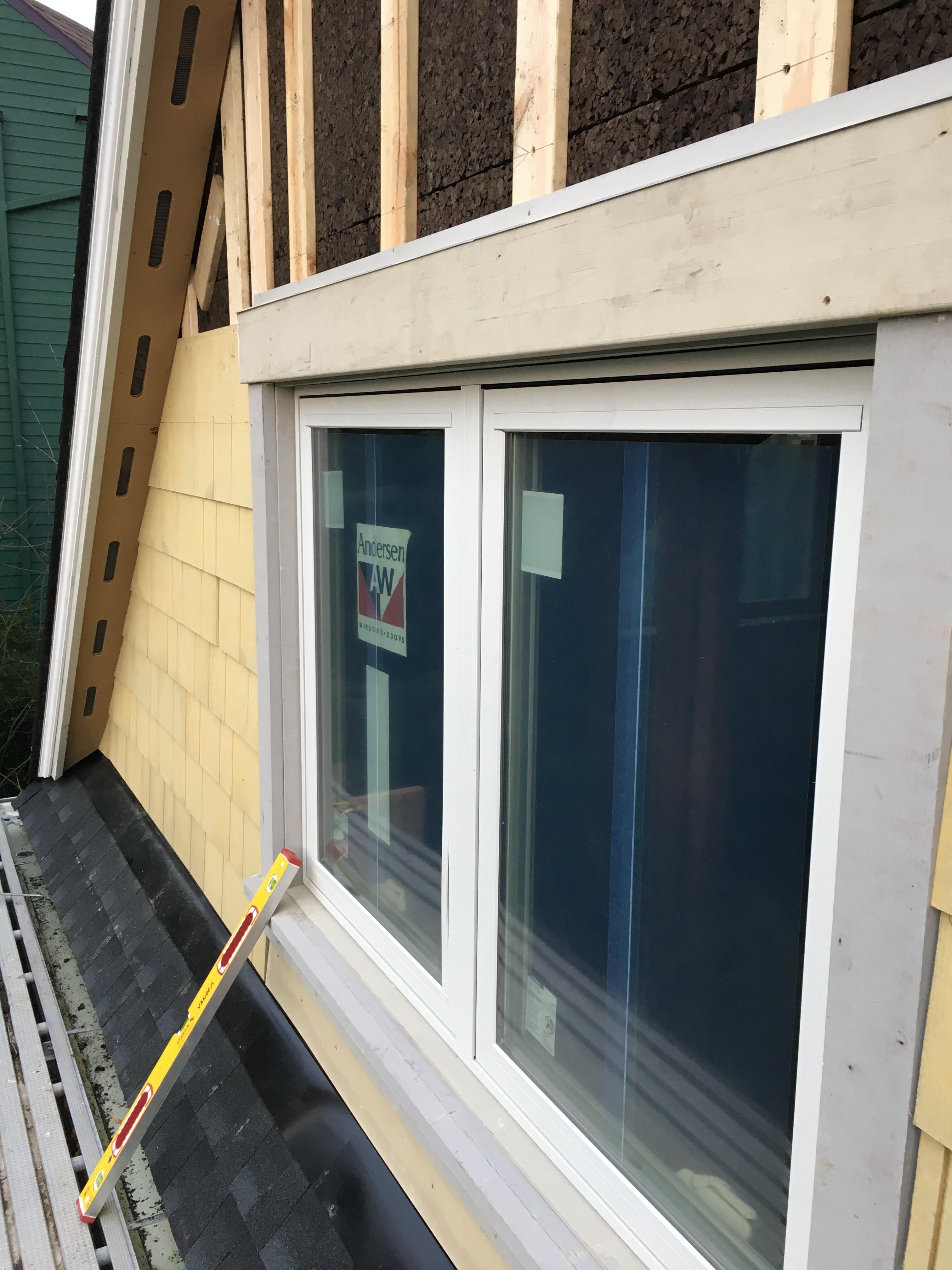
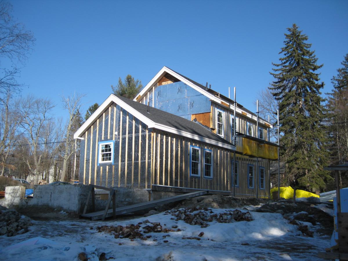
When existing houses are retrofitted to add continuous exterior insulation as part of a deep energy retrofit typically the drainage plane is moved to the face of the new insulated sheathing. This is especially true if the windows will be replaced. (For more on replacing windows, see the guide Complete Window and Frame Replacement.) If the windows are not being replaced and are not leaking, continuous exterior insulation may be added without re-flashing the windows; in this case, the location of the drainage plane can be maintained over the existing exterior sheathing.
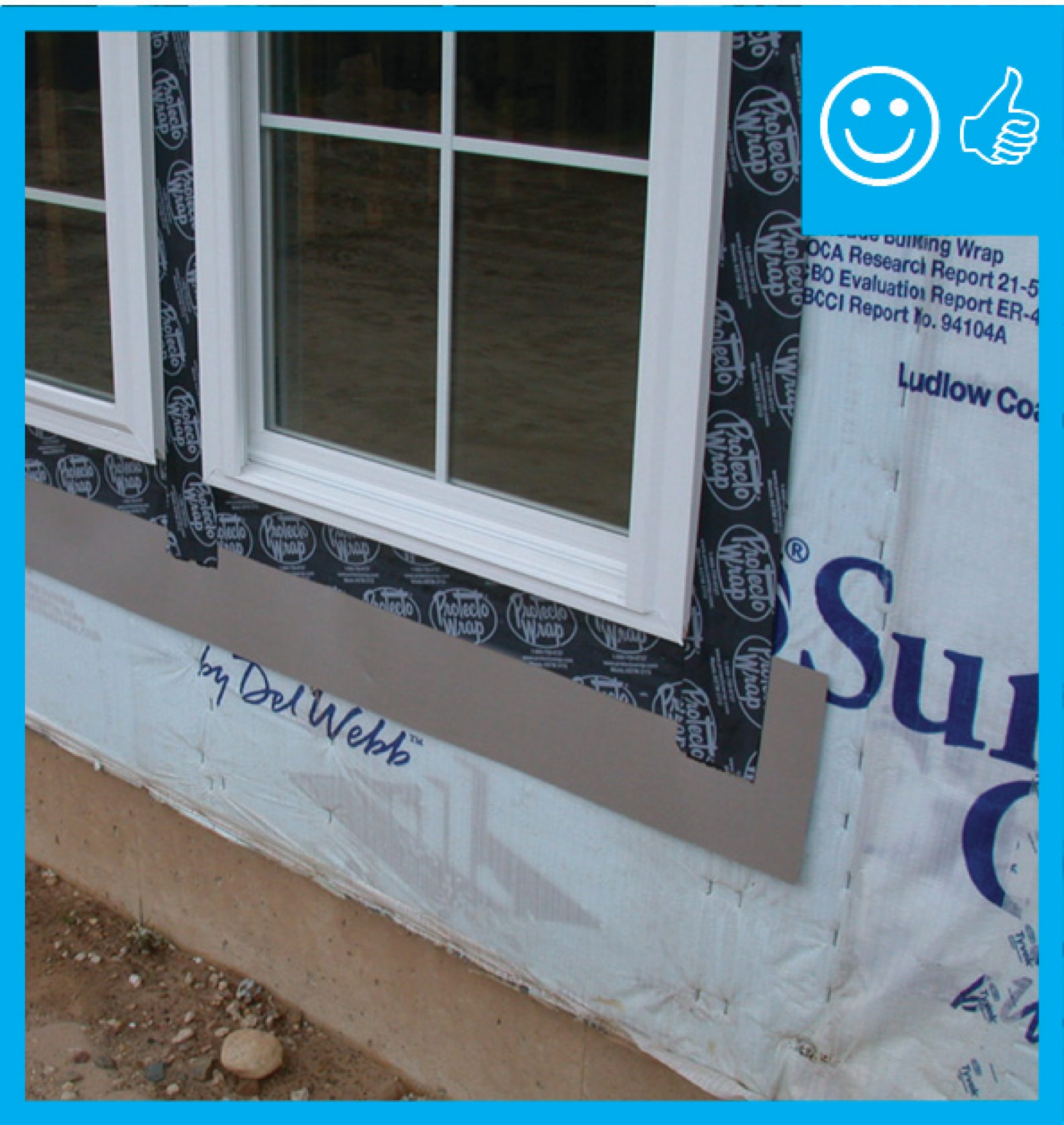
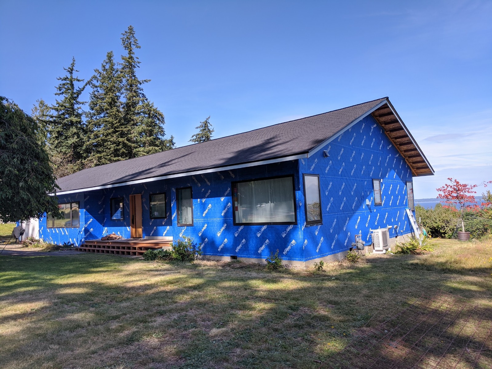
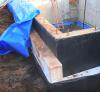
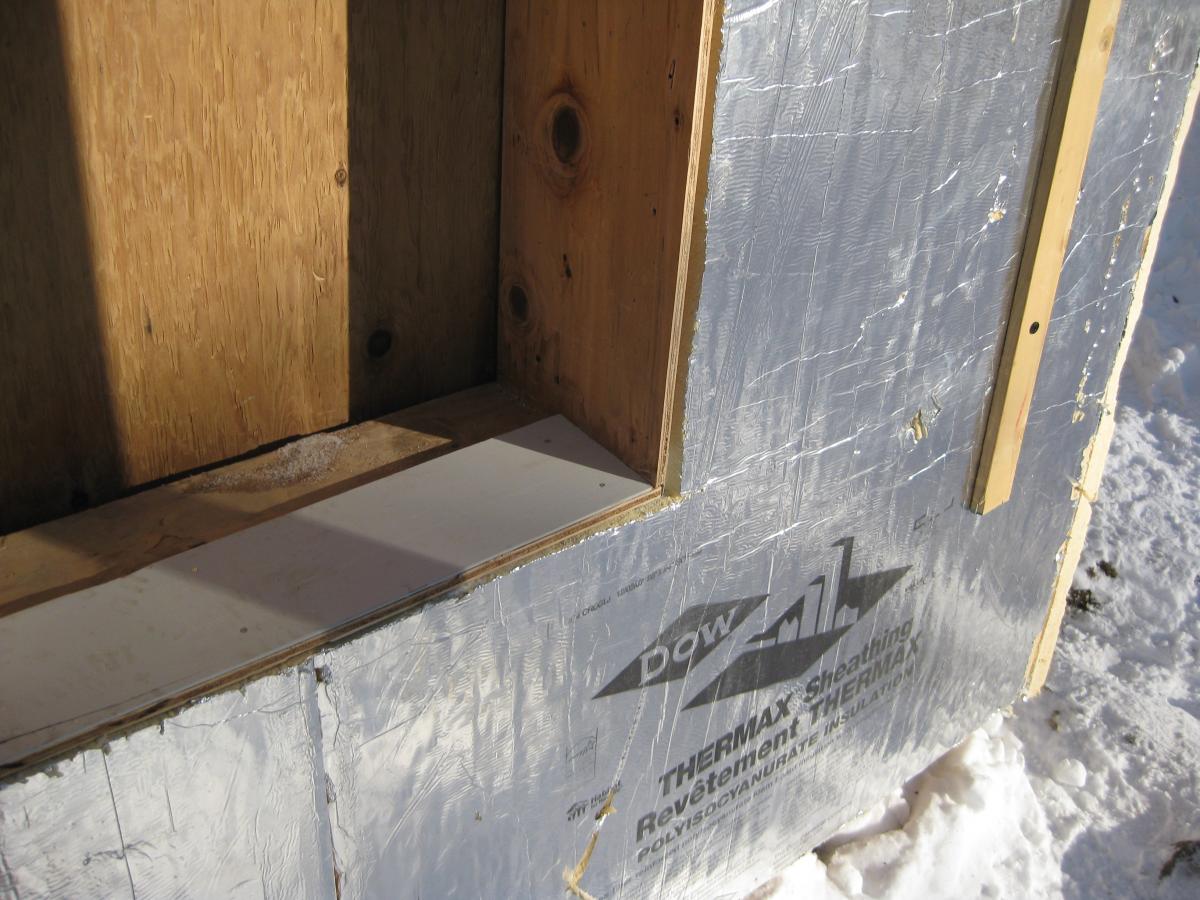
The new insulated sheathing should be installed as outlined in the Scope and Description tab. Figure 1 shows a house being retrofitted with taped insulated sheathing. Note that the windows and doors have been modified so that they are flashed to the face of the new insulated sheathing. A sill extension is often required to accommodate the build-up of the new insulation. Figure 2 shows a piece of siding providing this extension as well as a slope to the exterior to promote drainage. Good window flashing and water management practices should be followed here (see the guide Fully Flashed Windows and Doors). Caulk the sides of the sill extension to reduce the water load on the sheathing behind it, and alter the profile of the head flashings as necessary to accommodate the build-up of the new insulation.
Balconies, porches, and decks may require additional kick-out flashings to accommodate the increased wall thickness due to the addition of the insulation.
How to Add Insulated Sheathing
- Remove the existing cladding.
- Leave the existing water control layer (house wrap or building paper) in place.
- If the windows are also being replaced, flash the window framing to the face of the new taped foam sheathing, which will serve as the new drainage plane. Add framing lumber if needed to extend the sill to account for the added wall thickness.
- If the windows are not being replaced and the existing water control membrane (house wrap, building paper, fluid-applied membrane) is in good condition, it is not necessary to move the drainage plane to the face of the new insulated sheathing. The drainage plane can remain as is (behind the new foam sheathing, which does not need to be taped since it is not serving as the drainage plane) and, provided they are not leaking, the windows can remain flashed to the face of the existing water control membrane. In this case, create a small (1/16-inch to 1/8-inch) gap between the new insulated sheathing and the existing drainage plane by installing it over spacers, shims, or vertically run sill gaskets used as furring.
- Follow the recommendations outlined in the Scope and Description tabs.
COMPLIANCE
See Compliance tab.
More Info
Case Studies
References and Resources
*For non-dated media, such as websites, the date listed is the date accessed.
Contributors to this Guide
The following authors and organizations contributed to the content in this Guide.
Sales
Water Managed Walls = Wall Moisture Control System
Technical Description
Most exterior wall cladding systems leak. Wind pressure and capillary action can drive rainwater through the many cracks, joints, and small gaps in a building's exterior. With typical residential siding systems, it is nearly impossible to seal all those holes. Even if a builder succeeds in sealing a majority of the holes, using caulk on the exterior of the wall is not a long-term solution; the caulk will need to be reapplied fairly often. A more practical way to protect building exteriors from rainwater relies on a drainage approach. With this approach, any water that leaks through the cladding will run into a water-resistant surface and safely drain down and out of the wall. The water-resistant surface could be house wrap or rigid foam that is securely taped or sealed at all seams. . House wrap should be lapped over any exterior wall flashings installed around window and door openings or where roofs intersect walls. Any holes through the wall, such as for water spigots, exhaust vent outlets, HVAC line sets, or wiring for outdoor light fixtures and receptacles, should be carefully sealed or gasketed.
Questions? Comments? Contact our webmaster.