

Scope
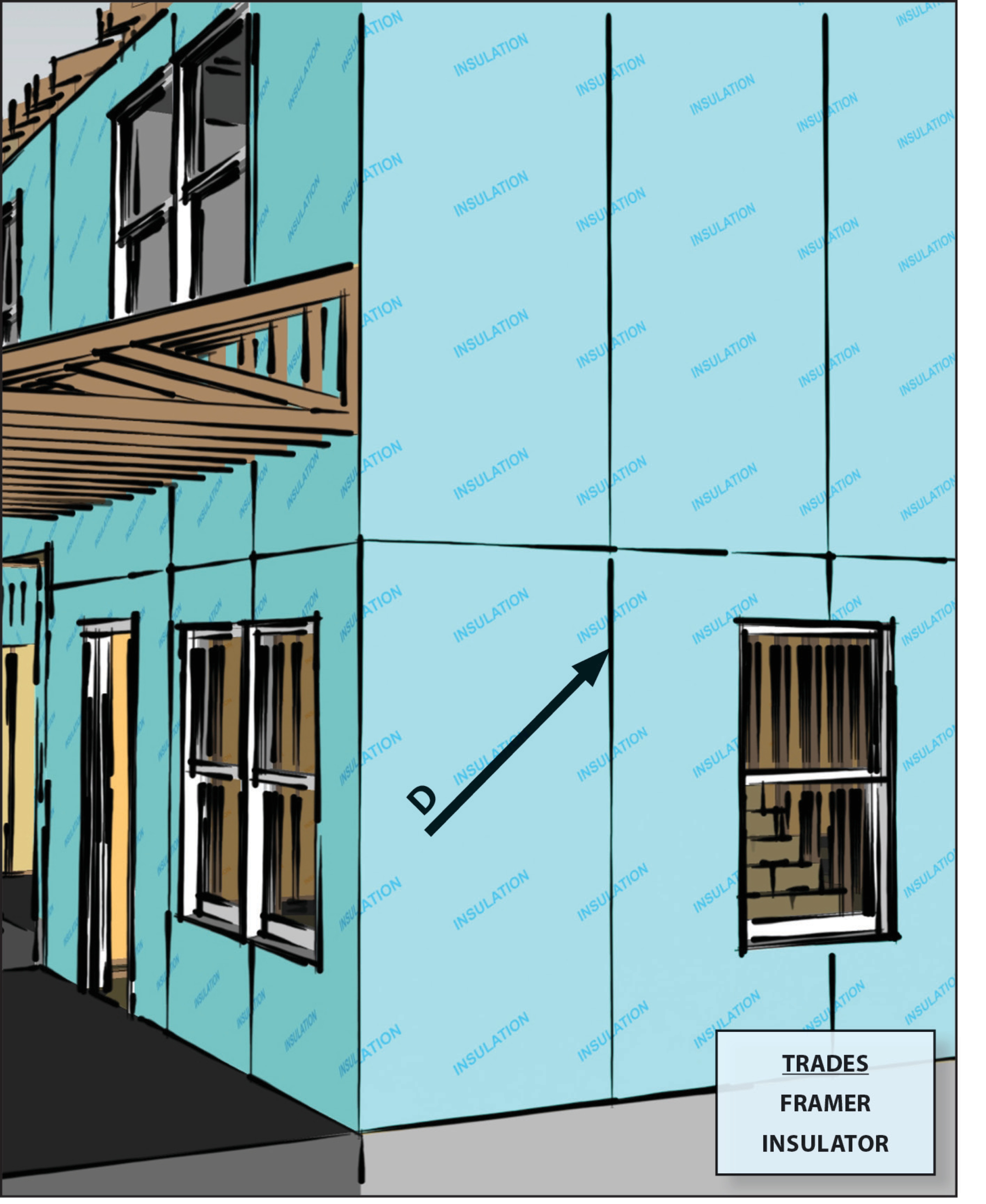
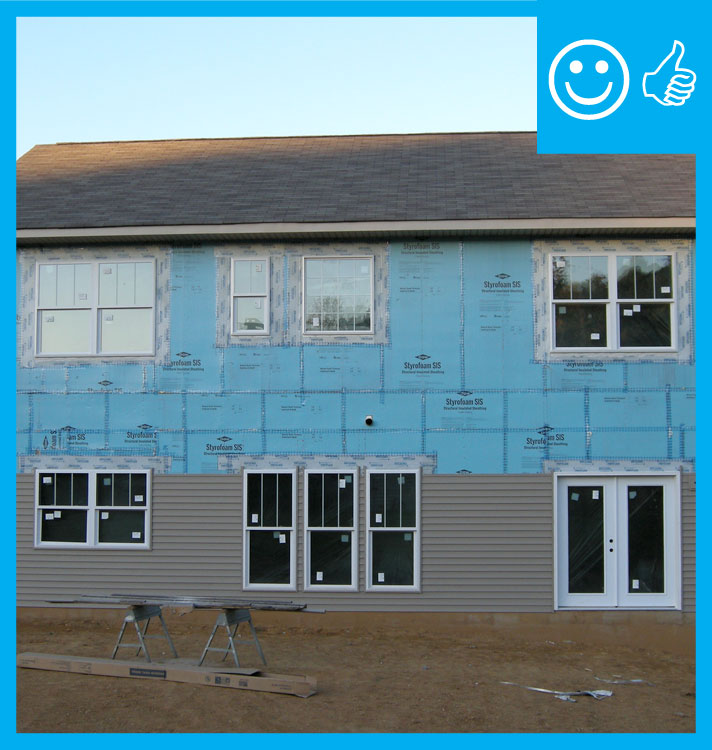
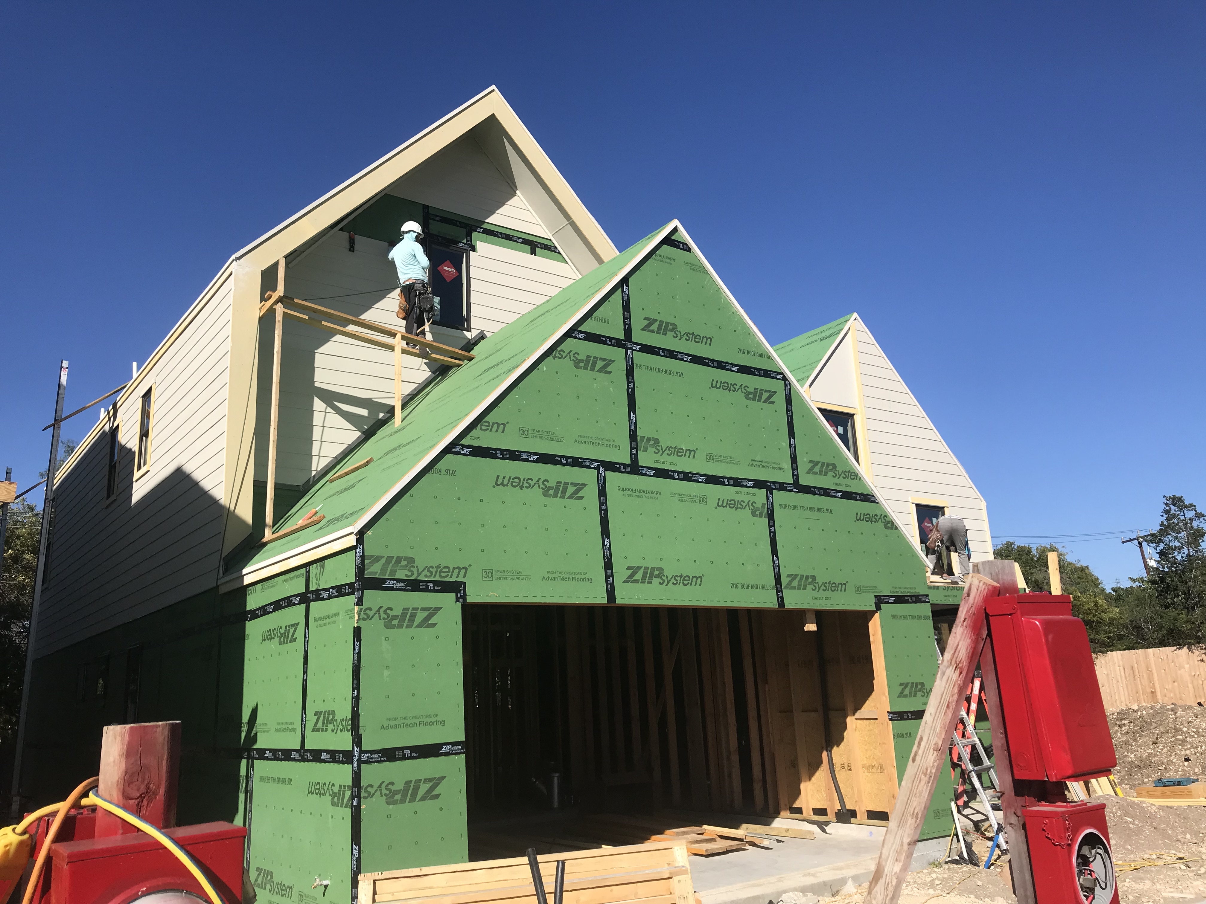
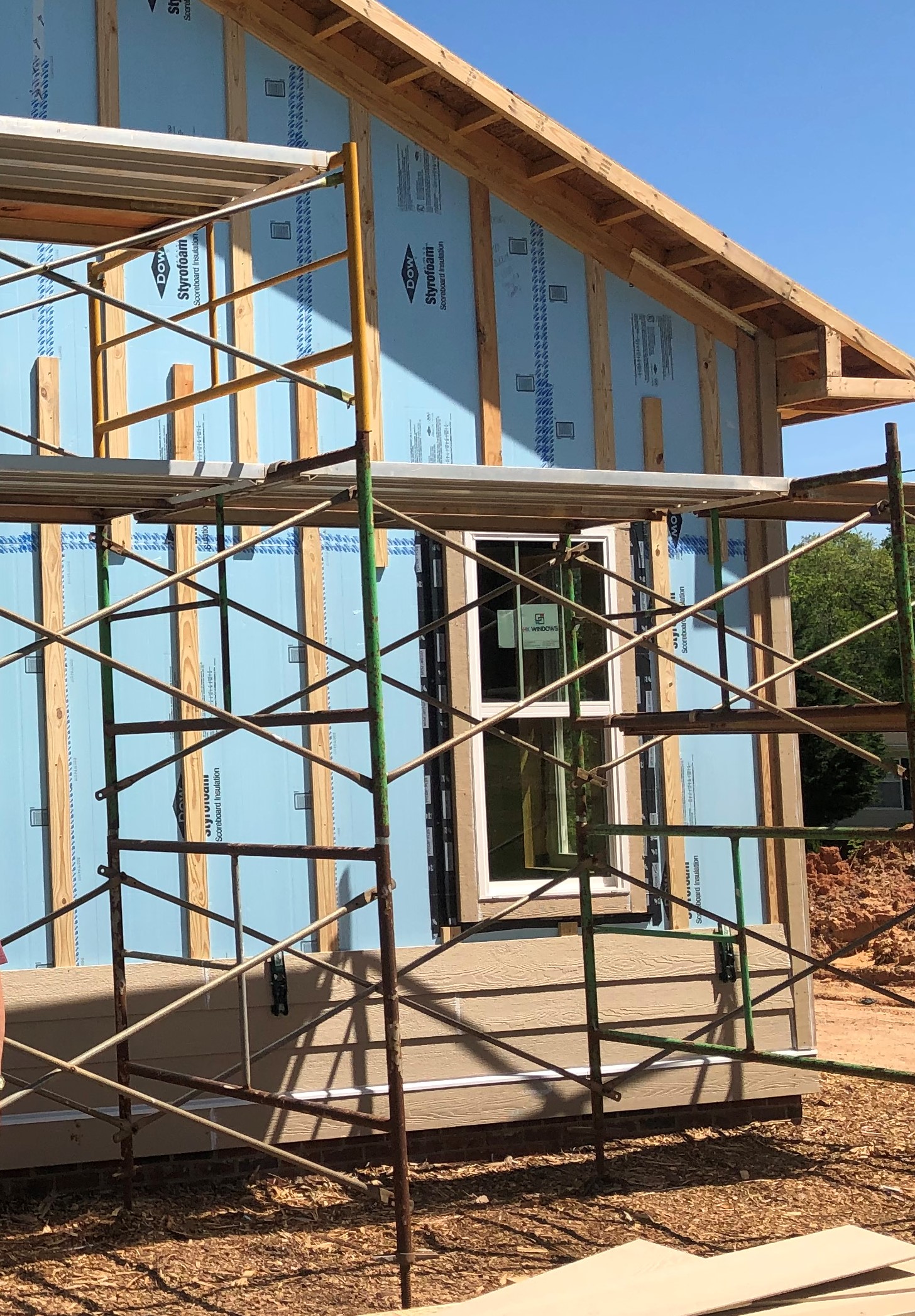
Install continuous rigid insulation or insulated vinyl siding to help reduce thermal bridging through wood- or metal-framed exterior walls.
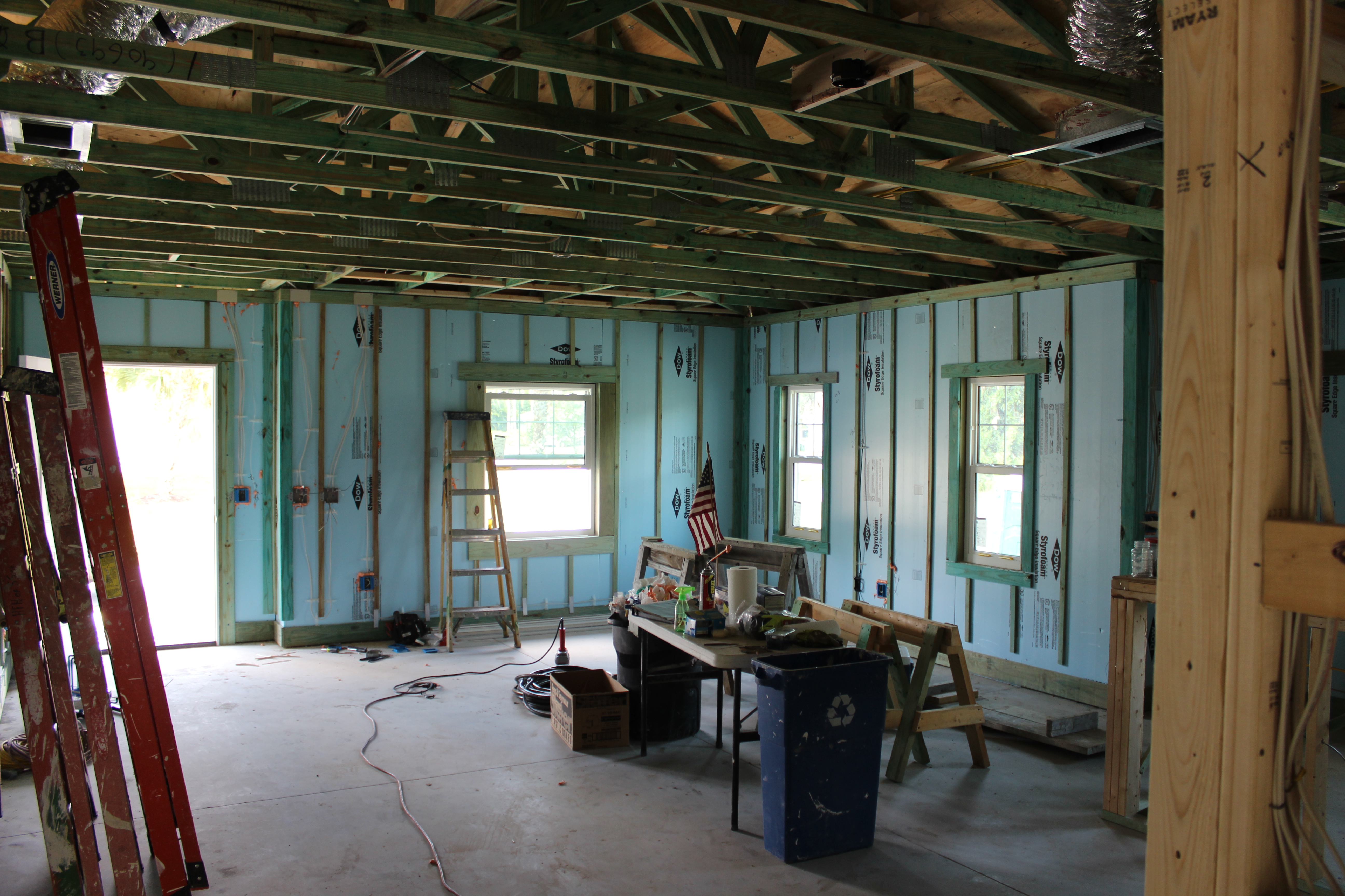
- Install rigid insulation over or in place of plywood, OSB, or other wall sheathing.
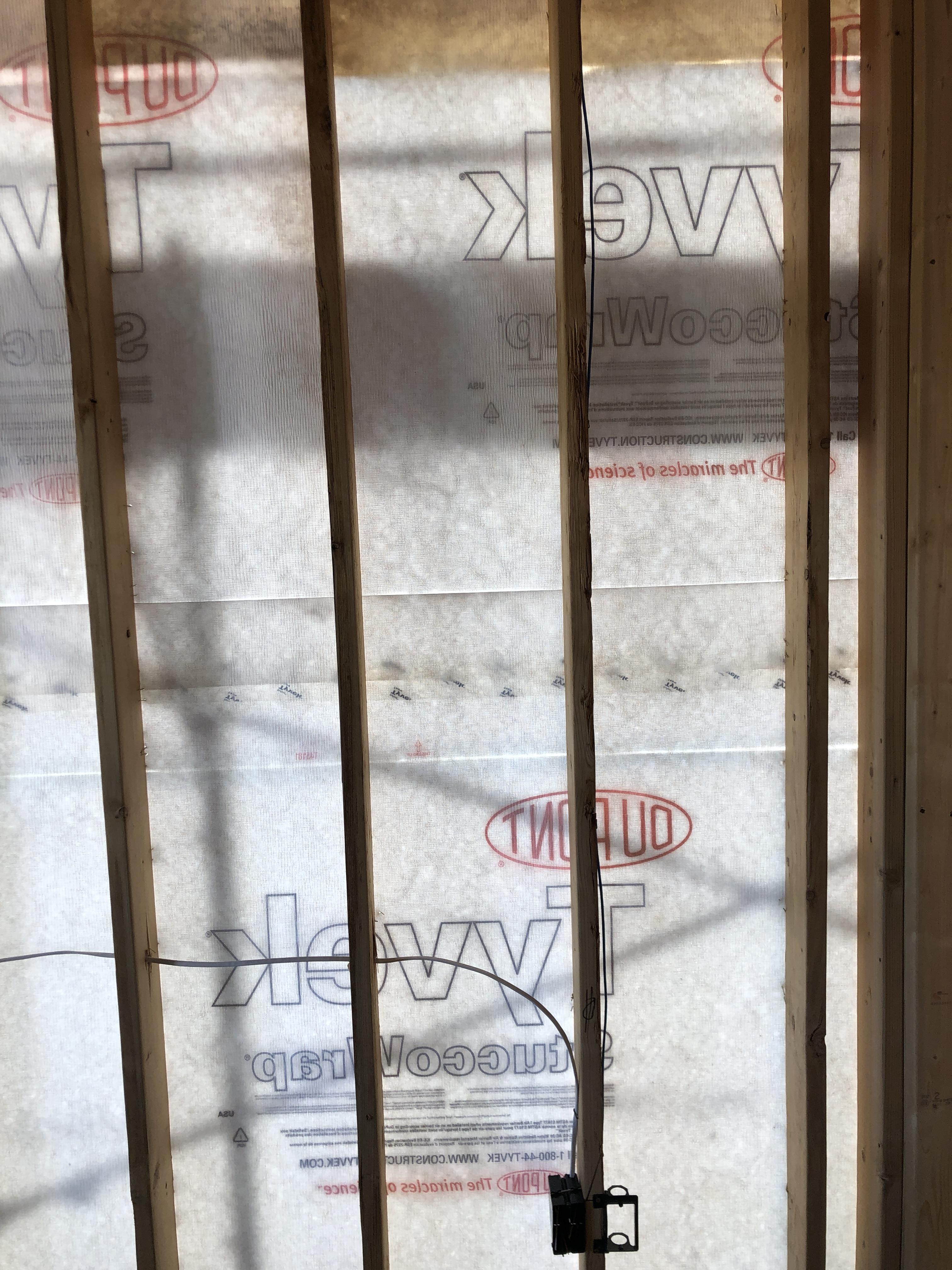
- Install over a water-resistant barrier. If rigid foam is rated for water resistance, no other water-resistant barrier is required, if seams in foam layer are sealed.
- Seal all seams in the rigid insulation with a compatible tape; apply tape to clean, dry surfaces.
- Install rigid foam or insulated vinyl siding over walls if they are metal framed.
See the Compliance Tab for links to related codes and standards and voluntary federal energy-efficiency program requirements.
Description
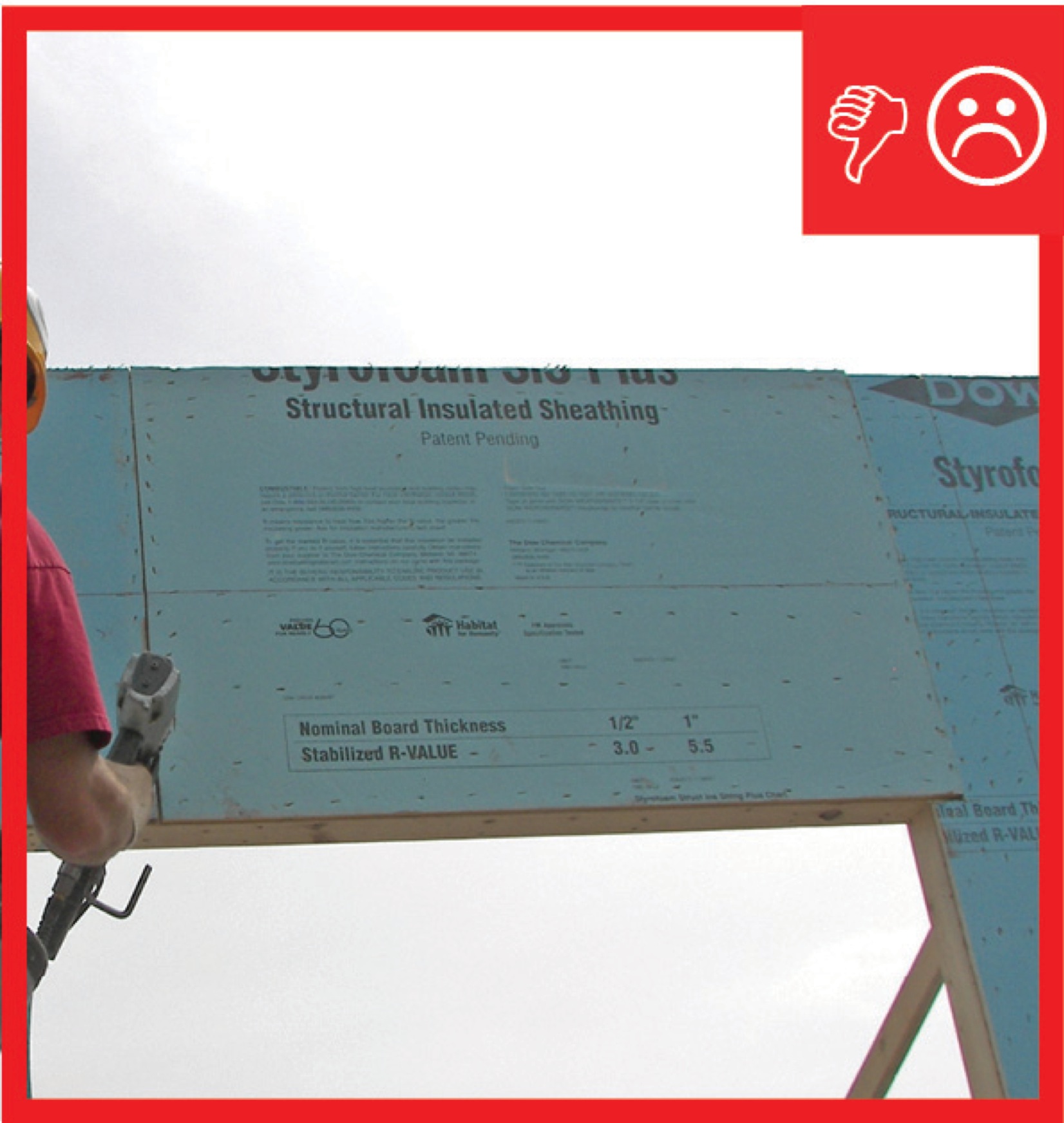
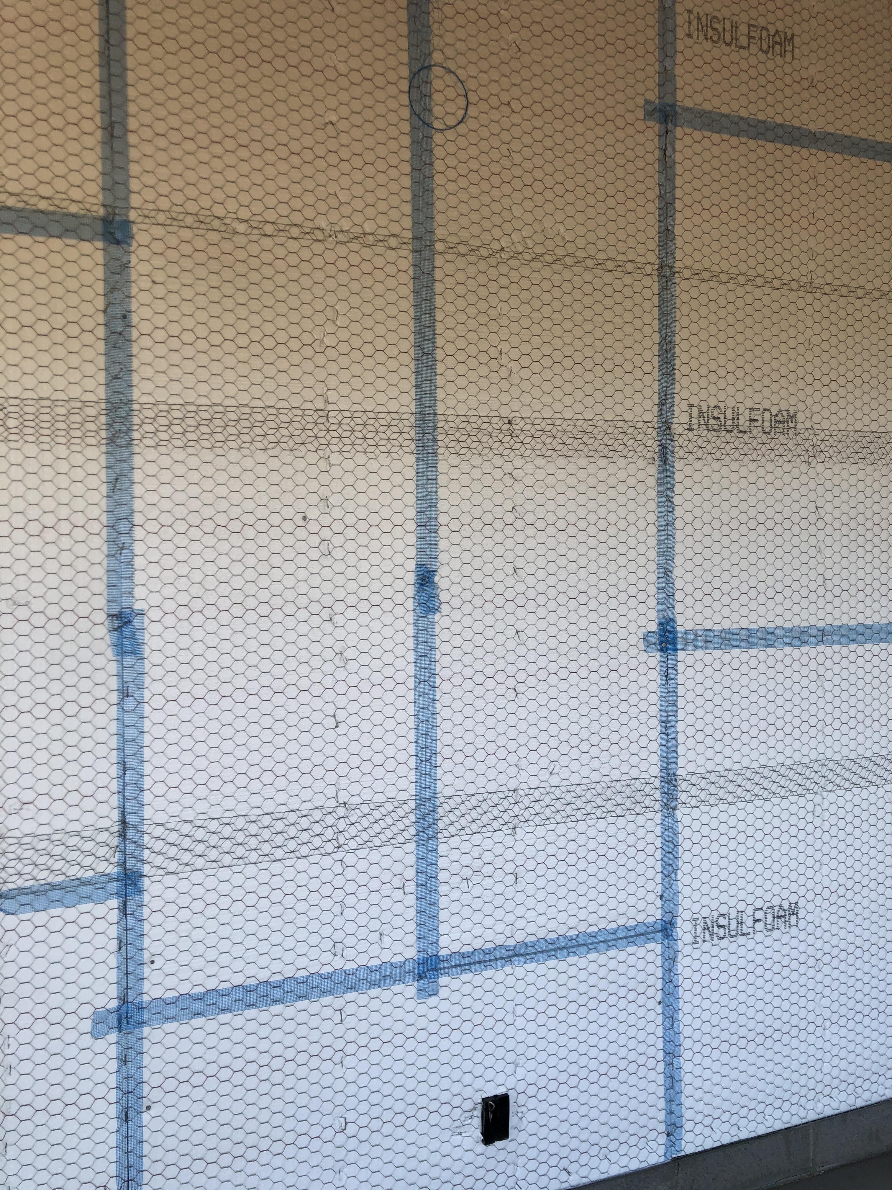
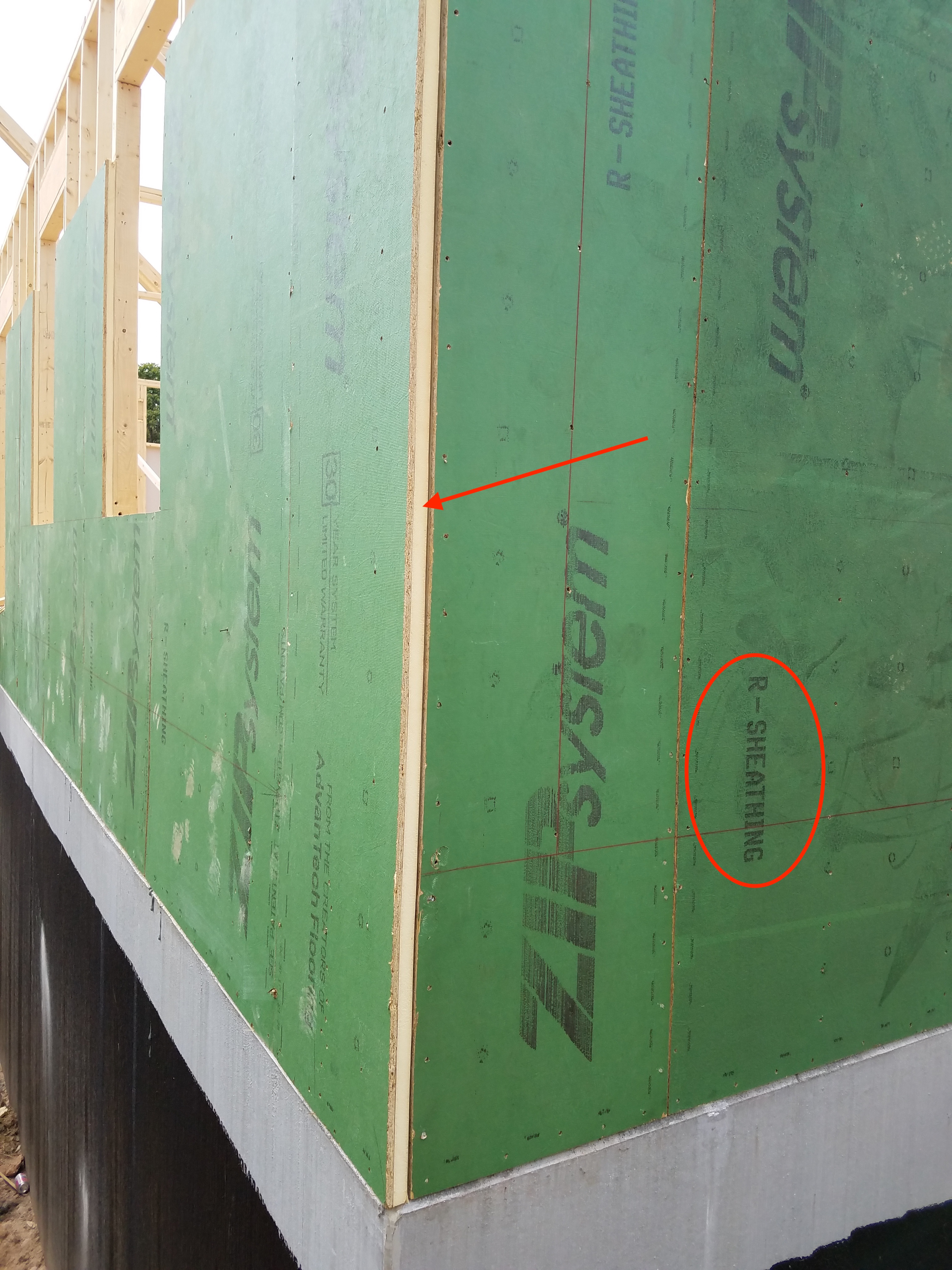
Continuous rigid insulation is a construction solution that provides a thermally efficient building enclosure. Rigid insulation sheathing is typically made of a rigid plastic foam that is sold in 4x8- or 4x10-foot boards. The boards are available in several thicknesses and R-values; 1-inch and 2-inch are common thicknesses. Rigid insulation provides thermal protection and it can also serve as an air and moisture barrier. This guide primarily describes rigid foam insulation products. Continuous rigid insulation boards are also available that are made from spun and compressed mineral fibers like glass wool or stone wool, or natural chopped and bonded fibers like wood or hemp.
Continuous rigid insulation provides an effective solution to thermal bridging. Thermal bridging occurs wherever assembly components with low R-values (such as wood or steel) span from the interior to the exterior of the building. Steel framing has an R-value of 0.04 per inch and wood has an R-value of 1 per inch. In comparison, rigid insulation has an R-value 3.2 to 6.5 per inch, depending on whether it is low-density or high-density (BSC 2007). In traditional building construction, while the wall cavities are filled with insulation, there is no insulation at the window frames, door frames, studs, top plates and bottom plates; together this framing comprises nearly one-fourth of the wall area. Rigid insulation can be attached to the exterior side of the framing to provide a continuous insulating layer that reduces thermal losses through thermal bridging.
Rigid insulation can also function to mitigate moisture problems in building construction. Rigid insulation can act as an integral part of the wall’s wind-driven rain screen and vapor and condensation management systems (see climate-specific factors).
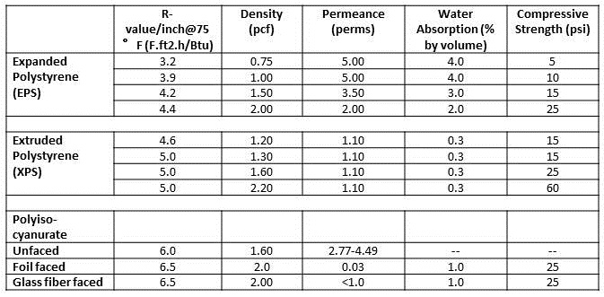
There are three types of rigid foam insulation: expanded polystyrene (EPS), extruded polystyrene (XPS), and polyisocyanurate (polyiso). EPS and XPS are thermoplastics, which are non-cross-linked polymers so they are susceptible to deterioration in high temperatures (BSC 2007). Polyiso is a thermoset, which is made up of cross-linked polymers so it has a much higher melting temperature. While properties can vary among specific products, XPS and polyiso tend to be higher density, higher R-value, and lower permeance than EPS (see Table 1).
When using foam insulation, you’ll need to decide whether you intend to use OSB in addition to the rigid foam to serve as the building sheathing or if the rigid foam layer will itself serve as the sheathing, and you’ll need to determine what will serve as the drainage plane and where this layer will be. These decisions are determined somewhat by climate.
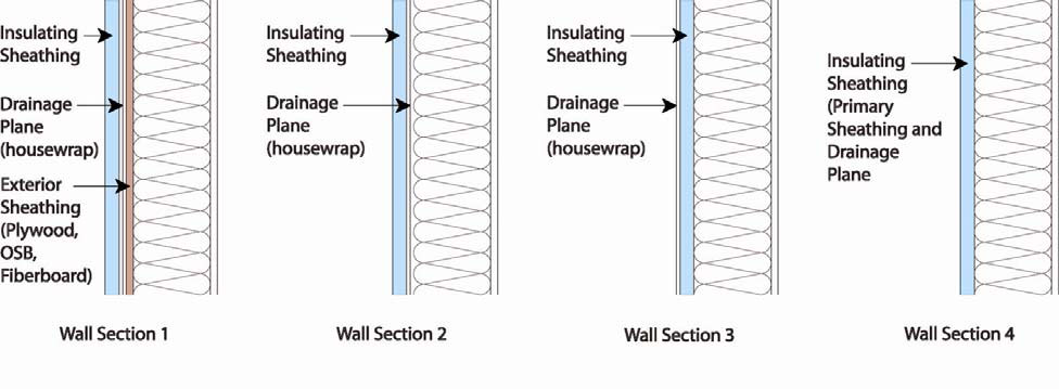
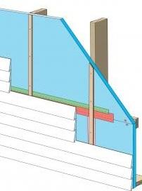
The wall sections in Figure 1 (BSC 2007) show four options for the drainage plane based on climate factors:
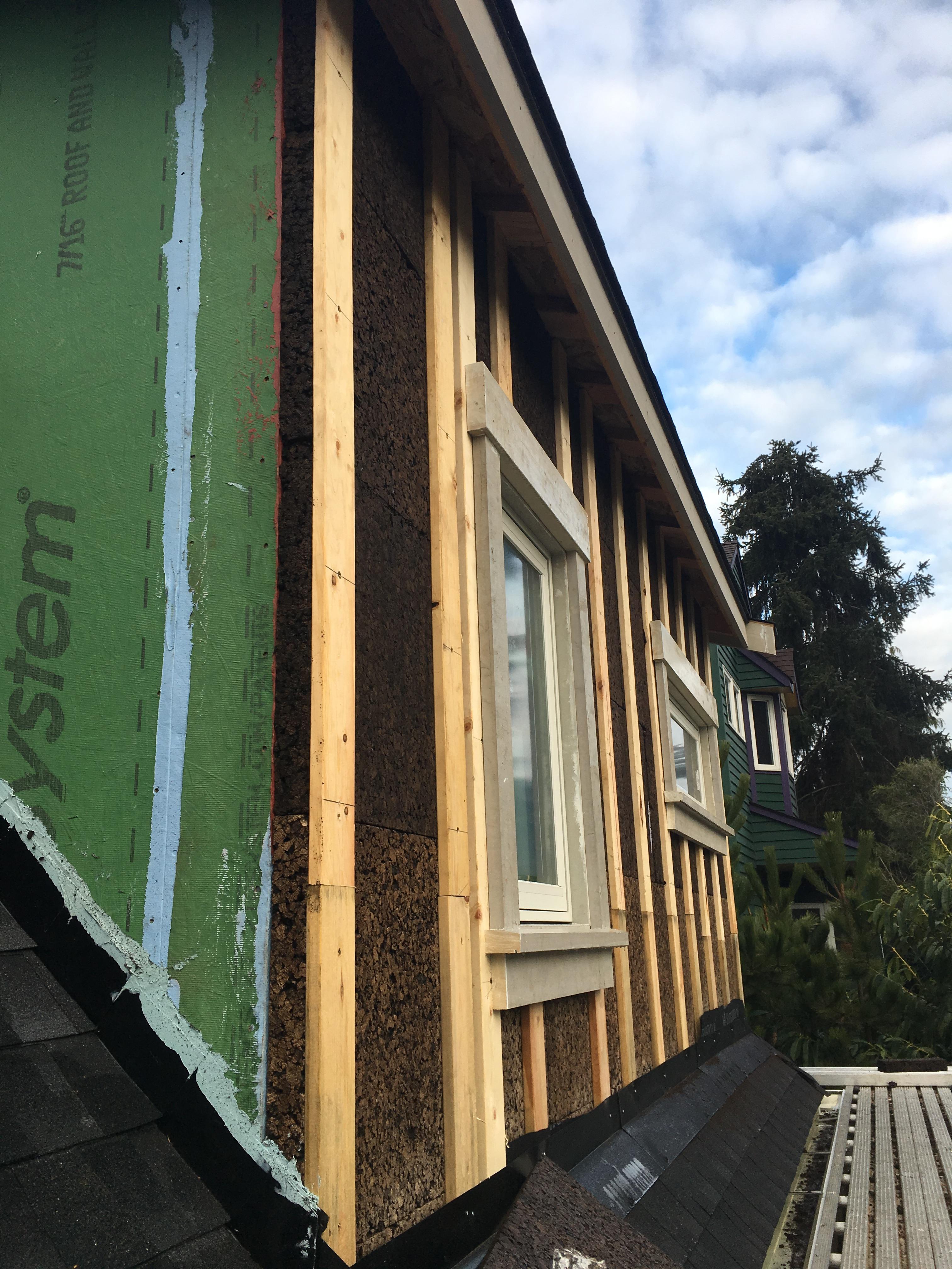
- Wall Section 1 - Insulating sheathing over house wrap over plywood or OSB – for regions with high winds and high rainfall. This strategy is the most durable assembly because the drainage plane (building paper or house wrap) is supported by the plywood sheathing and is protected against wind loading and other environmental factors by the insulating sheathing.
- Wall Section 2 - Insulation sheathing over house wrap over studs – for most rainfall zones but not best in high-wind regions.
- Wall Section 3 – House wrap installed over insulating sheathing over wood studs – ok for most rainfall zones but don’t use in high-wind regions. Fasteners used to install house wrap must reach through foam into studs.
- Wall Section 4 - Insulating sheathing as the drainage plane – ok in areas of limited rainfall and exposure. All vertical joints and penetrations must be sealed.
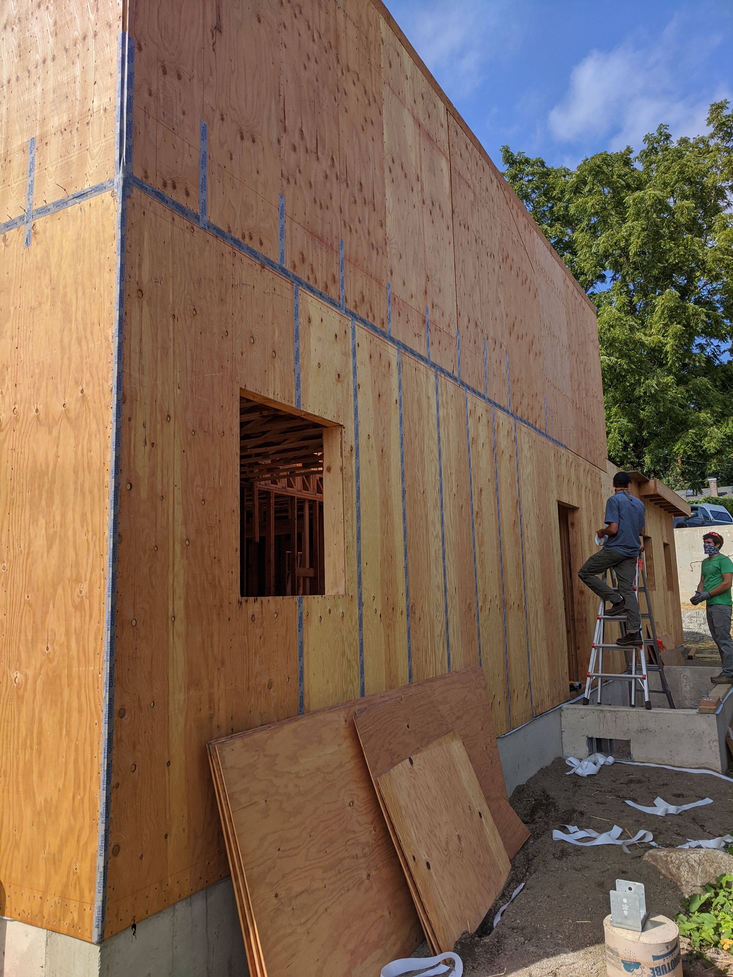
If rigid foam insulation will be used without OSB or plywood wall sheathing, determine what approach will be taken to meet local wind and earthquake code requirements. A common approach is to install exterior structural wood sheathing at the corners and at regular intervals as needed to meet code requirements for lateral load resistance. However, because the wood takes the place of the foam sheathing, it can create problems with drainage plane continuity and it leaves opportunities for thermal bridging.
Three recommended alternatives are allowed: metal cross bracing, inset shear panels, or structural insulated sheathing products. With metal cross bracing, the metal braces are thin straps that do not interfere with the installation of the insulating sheathing, for example, diagonal 1x4 let-in braces or diagonal T profile steel strapping. The capacity of the metal cross bracing, however, may not be adequate for areas with high-wind loads and/or seismic activity. In these locations, a more robust form of lateral load resistance may be needed. Inset shear panels can provide for high levels of lateral load resistance and can be used in all wind and seismic zones. Inset shear panels are wood-framed panels that fit within the stud spacing of the wall assembly, so the exterior face of the panel is flush with the exterior face of the wood studs. Another option is to use a structural insulated sheathing. It must be installed following the manufacturer’s installation recommendations and certified to meet structural requirements. When using any of these options, check the plans with local code officials before finalizing wall-sheathing layout.
Extruded polystyrene (XPS) and foil-faced polyisocyanurate (polyiso) are high-density rigid-foam insulations that can be used as exterior insulation and are generally approved to be used as a drainage plane if the joints are sealed. Insulation sheathing membranes rely on tape to complete the air barrier; the tapes should be applied on a clean, dry, warm surface. For the rigid insulation to be used as a water-resistive barrier, the vertical plane of the exterior face of the sheathing must be as smooth and continuous as possible.
One of the complications of foam plastic insulation is that it typically is less thermally stable and will expand and contract more than standard structural sheathing. This is why two layers of foam are often specified with joints offsetting, so if gaps open up they do not span the entire thickness of the foam insulation.
If you are using a structural insulated sheathing, then following the nail schedule provided by the manufacturer is very important to obtain the structural properties such as racking resistance that are mandated by codes. If a nonstructural insulated sheathing is used, nailing patterns become less important because the exterior cladding will be fastened through to the framing. Button cap nails are recommended by most sheathing manufacturers to maintain the holding strength and to avoid blow off during high winds before cladding installation.
Furring strips can adequately support the weight of the cladding and resist wind and seismic forces if the right fasteners and spacing are used. The following is recommended:
- Furring – wood 1x4s or 20-gauge steel
- Fasteners - long enough to penetrate studs by at least 1½ inch if wood, by three threads if steel.
- Foam Density. Use one of the following foams or foam with a greater density than these: Type II EPS or Type X XPS (per ASTM C578); Type 1 polyisocyanurate (per ASTM C1289) or Type IVB mineral fiber board (per ASTM C 612).
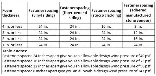
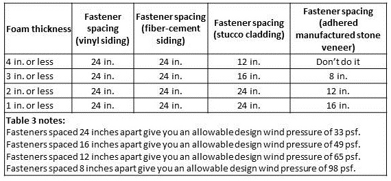
- Fastener Schedule – as specified by the foam manufacturer, see examples in Table 2 for walls with studs spaced 16 in. on center and Table 3 for walls with studs spaced 24 in. on center (Holladay 2012).
Installing siding over rigid foam resembles standard installation, yet requires longer fasteners if fastening to the framing. With thicker insulating sheathing, longer and stronger fasteners will be needed to avoid cladding creep.
Stainless steel nails are the best choice, especially if the siding is to be finished with transparent or semitransparent stain. Use No. 304 stainless for general siding applications and No. 316 for seacoast exposures. Hot-dipped galvanized steel (per ASTM A 153), aluminum, and stainless steel fasteners are all corrosion-resistant and are acceptable. Electroplated and mechanically galvanized fasteners are not recommended. For best results, use “splitless” ring shank siding nails. These have thin shanks and blunt points to reduce splitting. Textured heads should be used to reduce the glossy appearance of the nail head. Hand nailing is preferred. The size of nails to use depends on the type and thickness of the siding. Use nails long enough to penetrate solid wood (sheathing and blocking or studs) a minimum of 1.5 inches. However if you use ring shank rather than smooth shank nails, ¾ in. penetration into solid wood should be adequate, unless you are building in high-coastal wind areas (Holladay 2012).
Insulated Siding
Some brands of vinyl siding are manufactured with a layer of rigid foam adhered to the back. In order for insulated siding to qualify as home insulation, it must be installed directly over a water-resistive barrier and sheathing. When insulated siding is installed over furring strips, the space between the furring strips must be filled in with rigid insulation or another appropriate building material. Insulated siding installed over furring strips alone would not be considered home insulation.
How to Install Rigid Insulation
Lay Out
- Lay out the insulating sheathing panels so that vertical joints do not occur at the corners of window and door openings or over window heads if possible (BSC 2007).
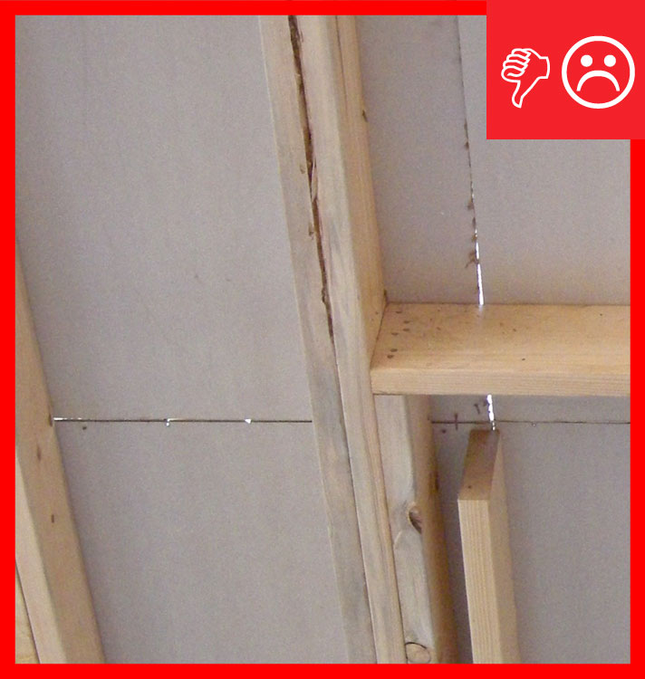
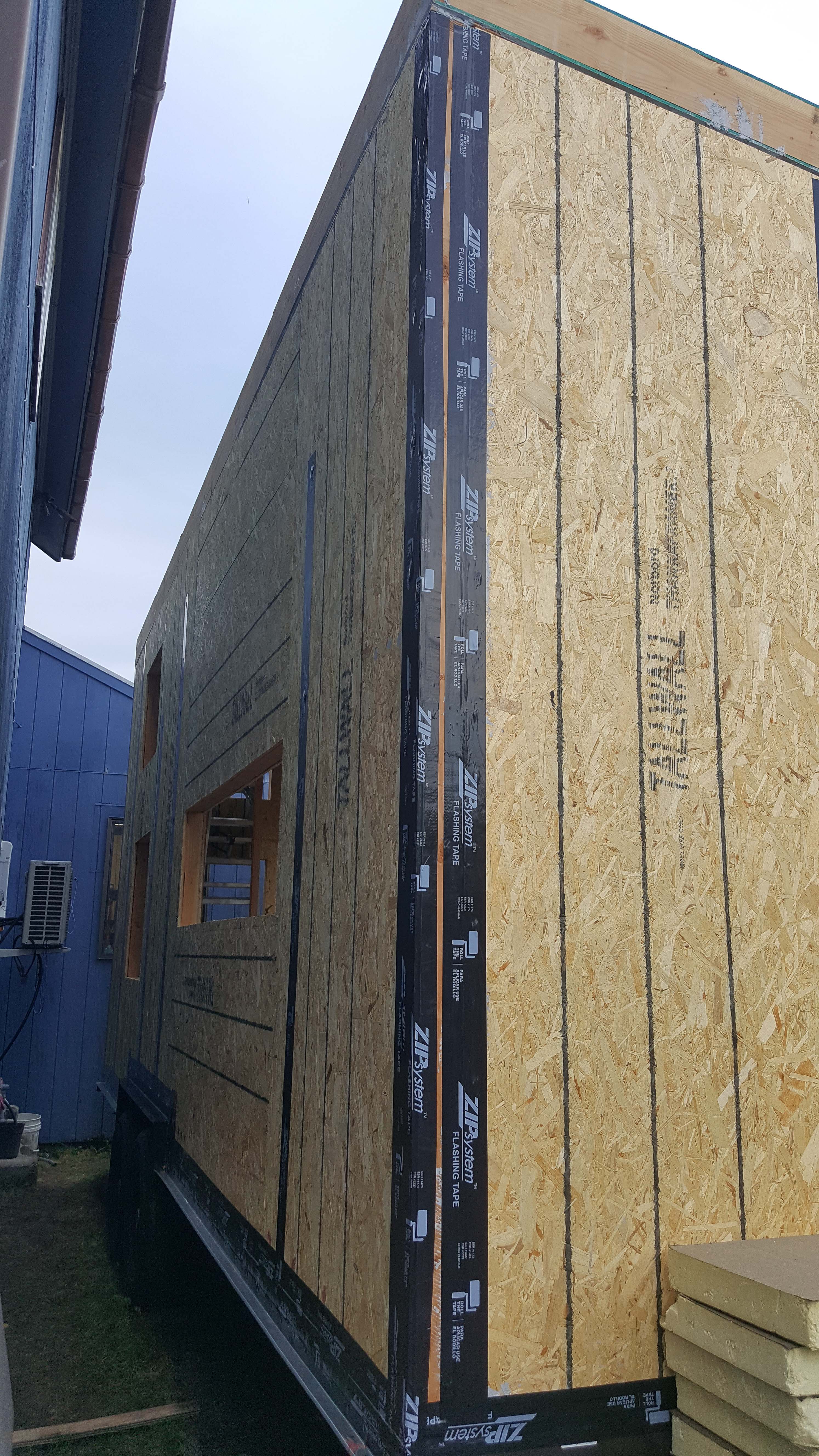
- Install rigid insulating sheathing vertically with long joints in contact with one another per manufacturer’s specifications. This is particularly important when the sheathing is structural.
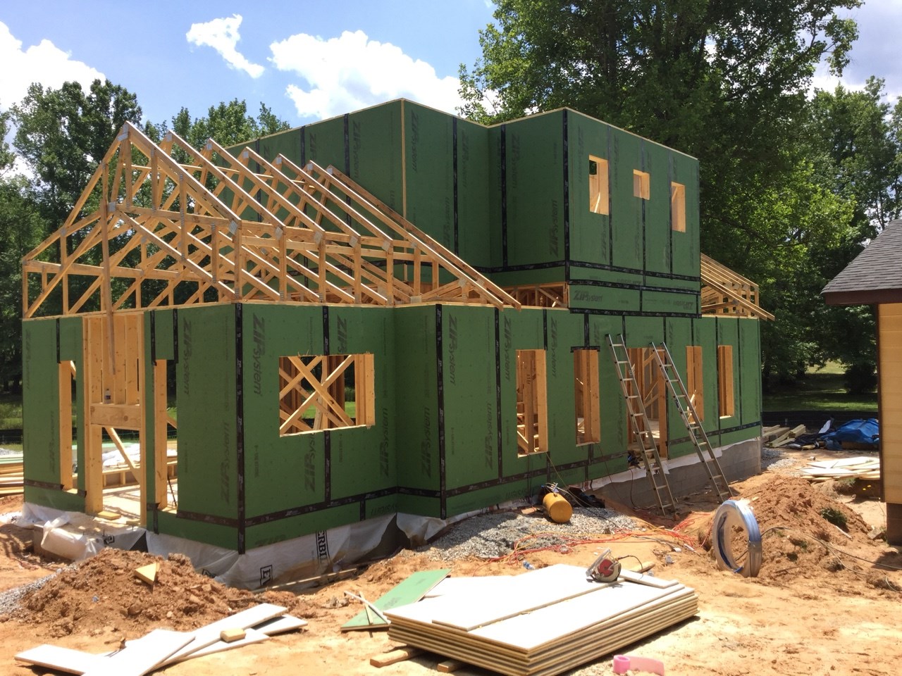
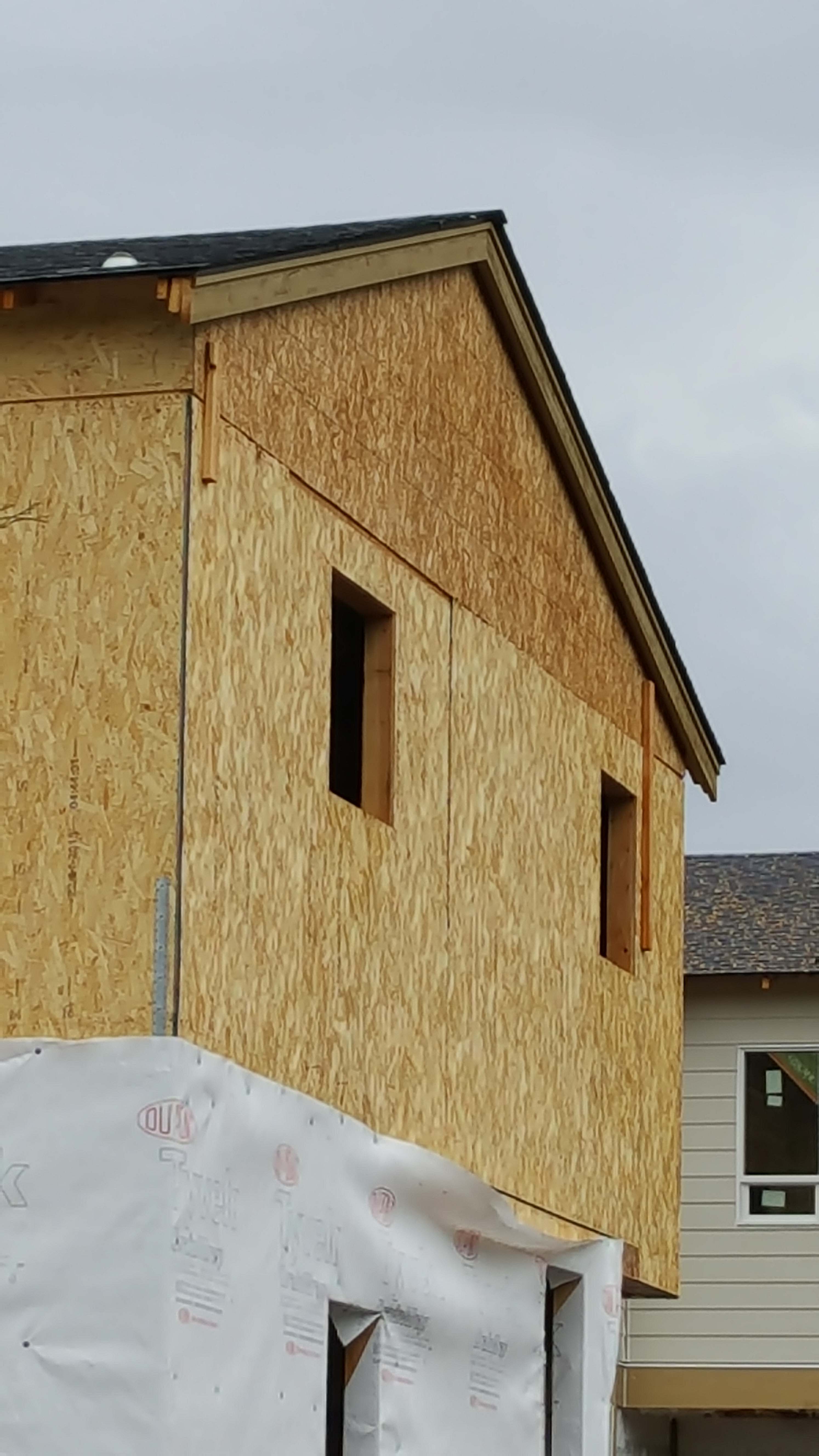
- Install the rigid insulation so that it extends down to cover the sill plate on the foundation wall and up to the underside of the roof truss. If desired, the insulating sheathing can extend above the top plate (notch around the roof trusses) to act as a wind shield for the attic insulation (BSC 2007).
- When rigid insulating sheathing is installed directly on the framing, apply a continuous bead of manufacturer-approved caulk sealant (solvent-based sealants are typically not approved by the sheathing manufacturer) to the top and bottom plates to reduce air leakage into the wall cavity.
- If you are installing more than one layer of rigid foam, then stagger the seams of the second layer to improve airtightness and reduce the chance of thermal bridging. Seams between foam sheets should be sealed with caulk, canned foam, or a compatible tape (Smegal and Lstiburek 2012).
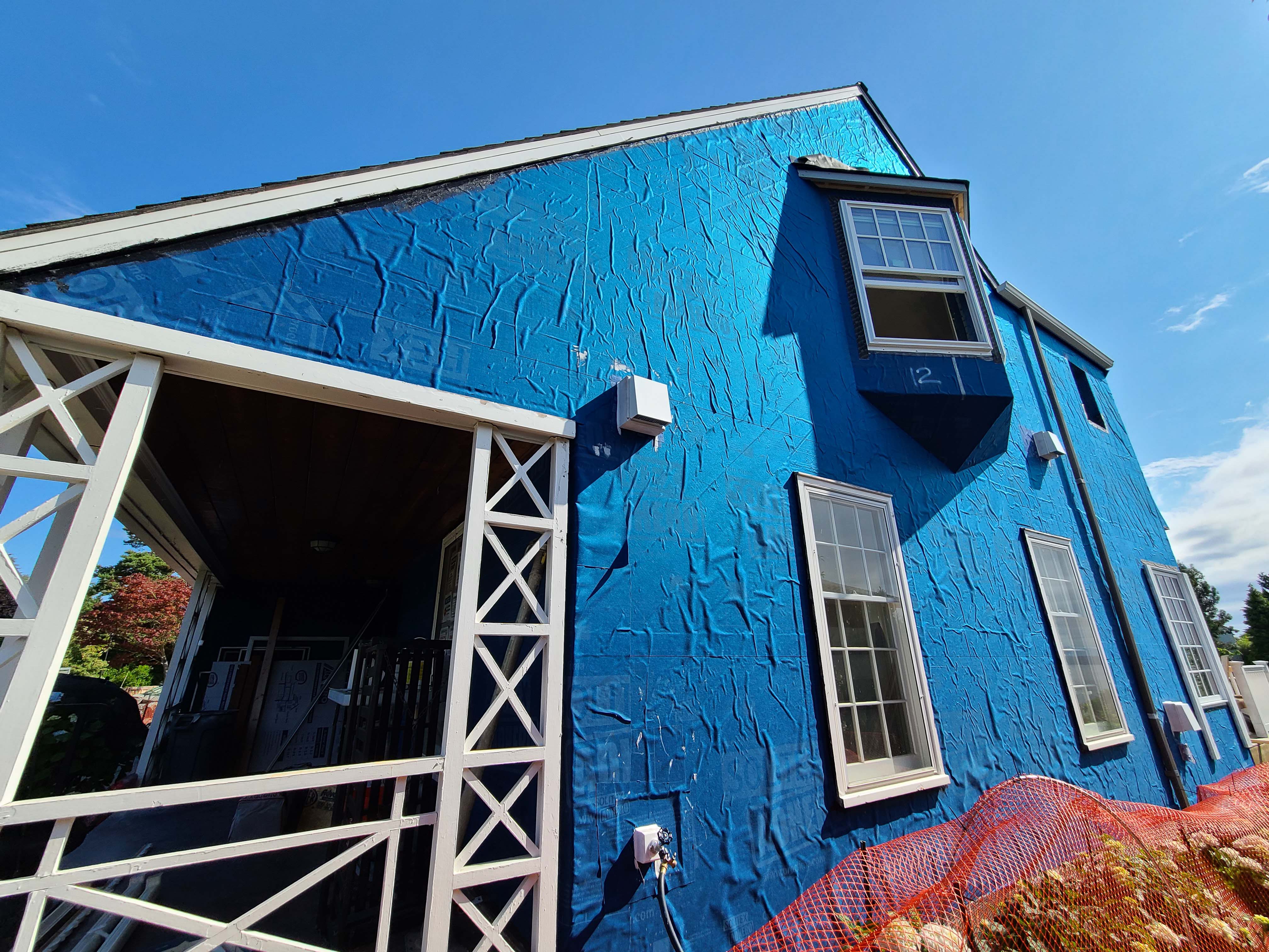
- If house wrap is installed, it is preferable to install it to the exterior of the rigid foam insulation.
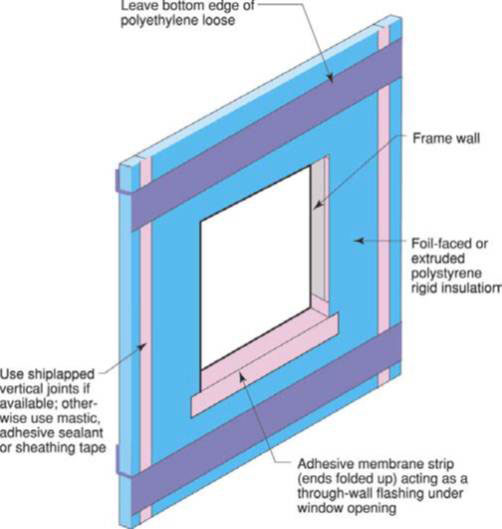
Figure 2. Lay out the rigid foam sheathing joints so they do not align with the window and door edges. - Fastening
- Follow the nail schedule provided by the manufacturer.
- Drive the nail through the foam board and into a stud until the nail's cap rests flush against the foam board's exposed surface. Fasteners should penetrate framing at least three-quarters of an inch.
- If furring strips are not specified, then drive nails every 12 inches around the foam board's edges.
- Drive nails every 16 inches into studs that run through the center of the board.
- Measure and cut subsequent rigid foam boards to precisely fit against previous boards.
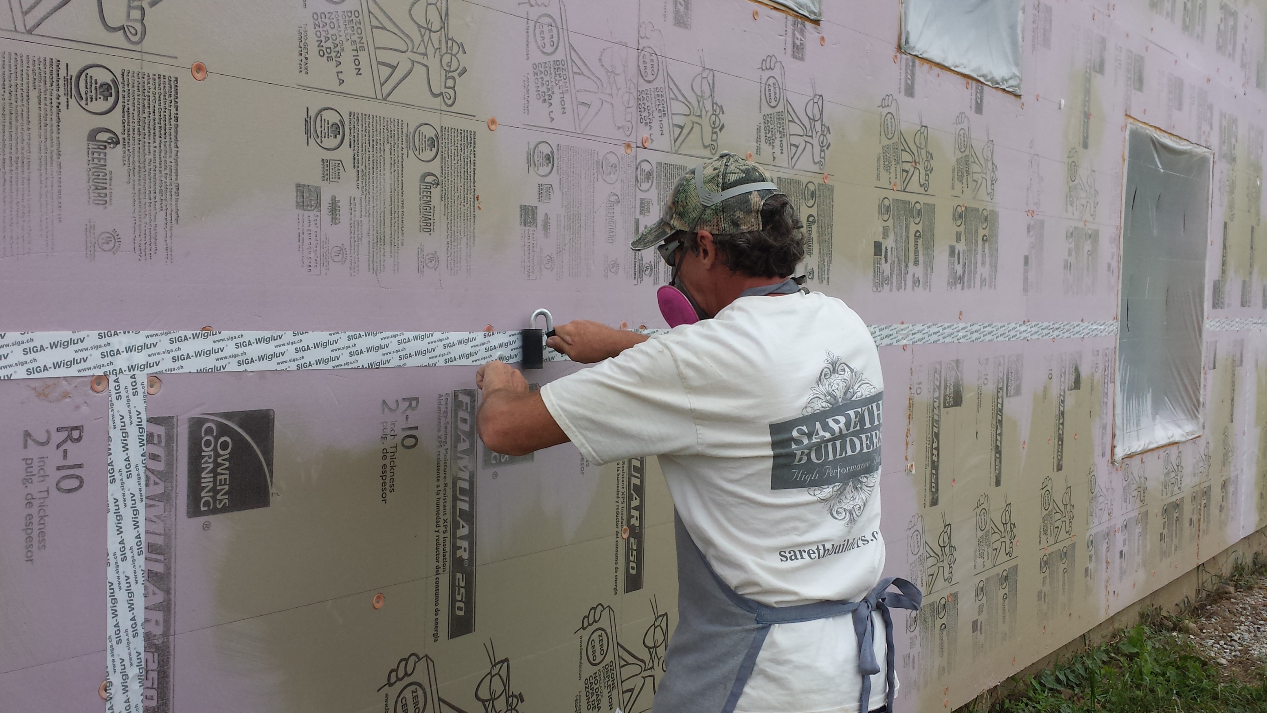
Taping
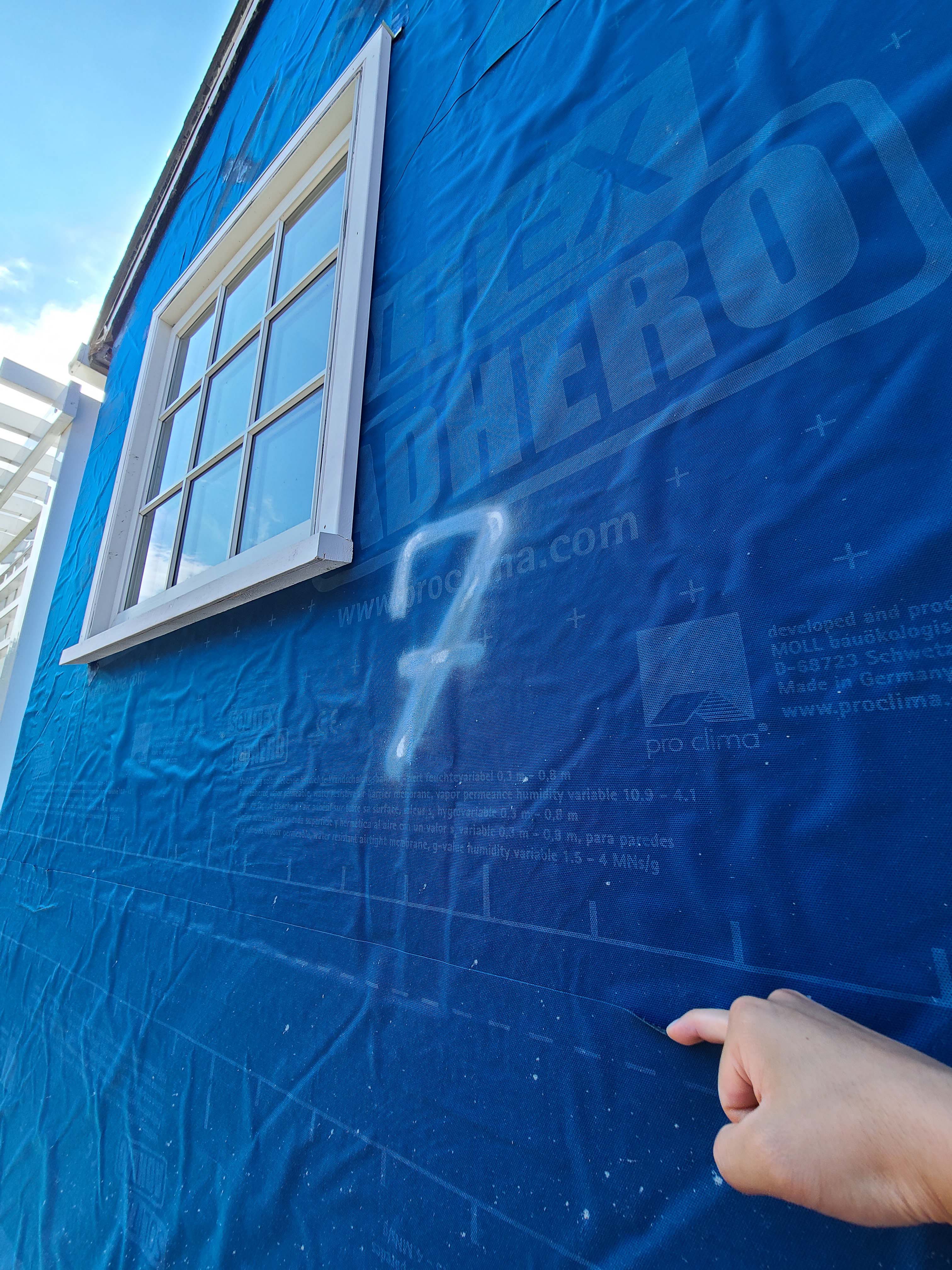
- When rigid foam is used as the weather-resistive barrier and/or the air barrier, tape all seams using manufacturer-recommended tape per the manufacturer’s instructions. Wipe the surface of the foam with a clean dry cloth before taping to ensure good adhesion by removing dirt or oil residue which is common on foil-faced polyiso (Smegal and Lstiburek 2012).
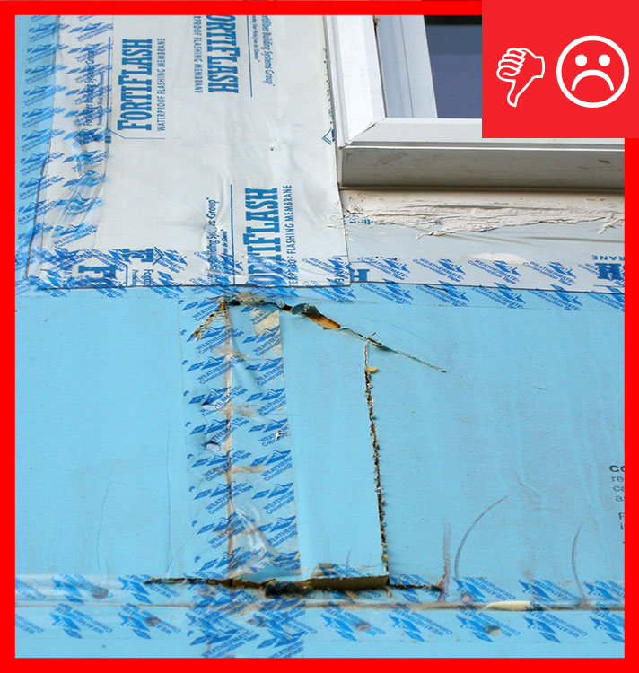
- When rigid foam is used as the weather-resistive barrier, apply flashing shingle fashion around all openings for doors, windows, etc., to reduce bulk moisture intrusion and air infiltration.
- Center the tape over the joint to cover the fasteners. Fasteners located in the center areas of the boards do not need to be taped. Use a shingle fashion technique when taping joints. Avoid taping during extremes in temperature; install tape per the manufacturer’s instructions, which is generally between 15°F and 120°F.
- Apply pressure along the entire surface for a good bond. Remove all wrinkles and bubbles by smoothing the surface and, if necessary, repositioning.
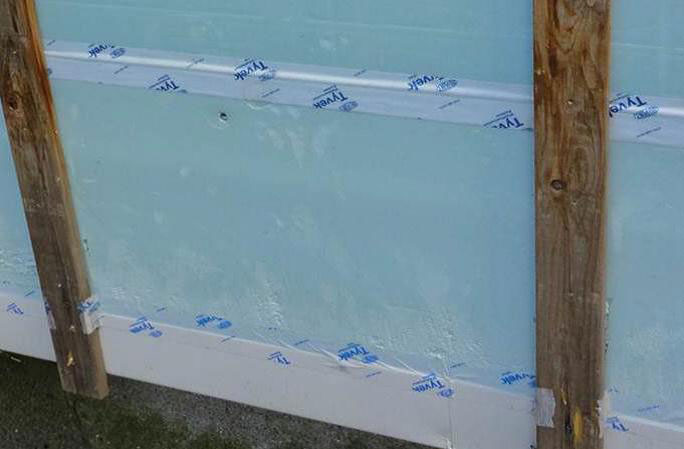
Figure 3. With a quality installation, tape can last a long time. This sheathing tape was applied 15 years ago. Flashing
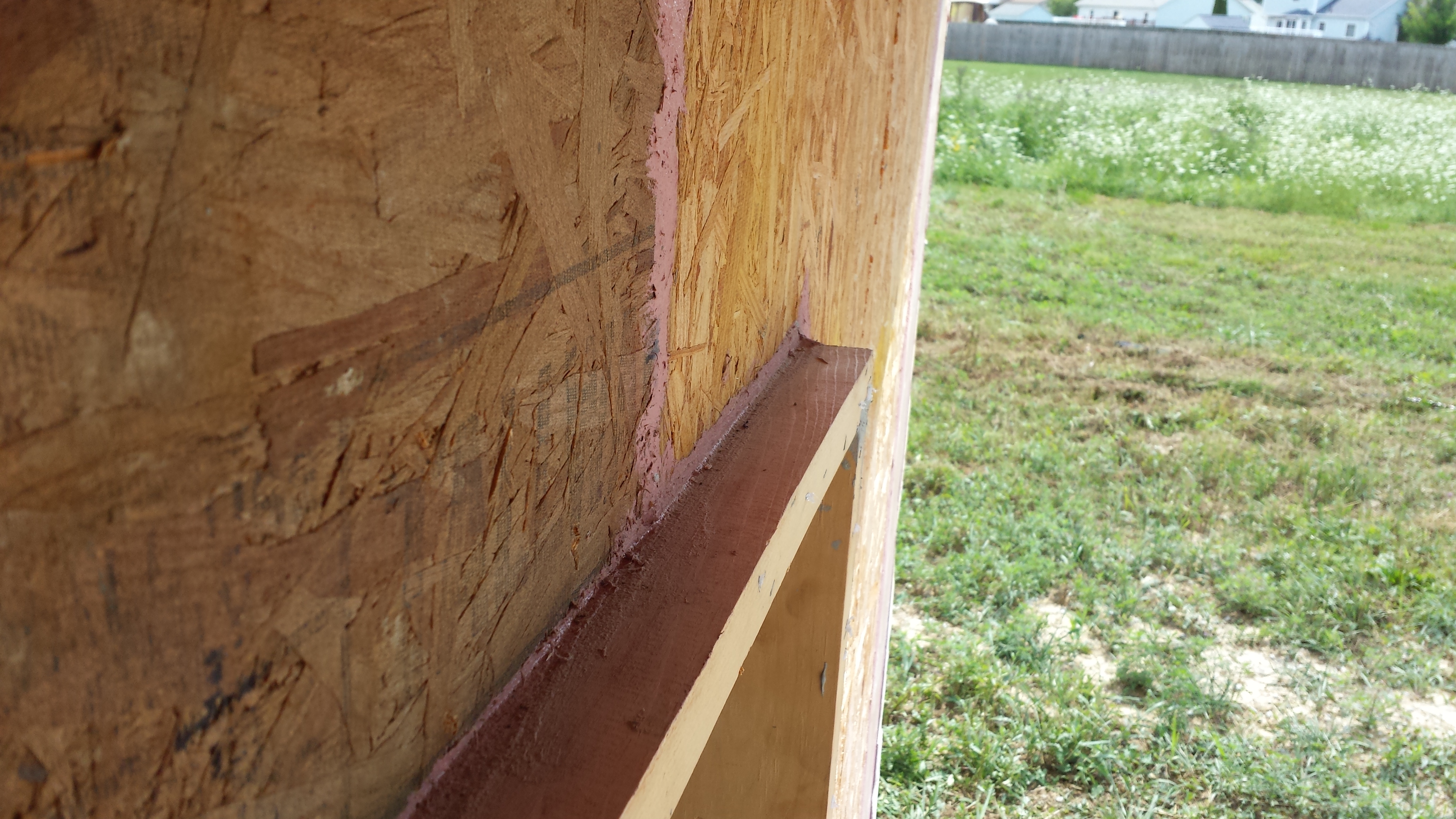
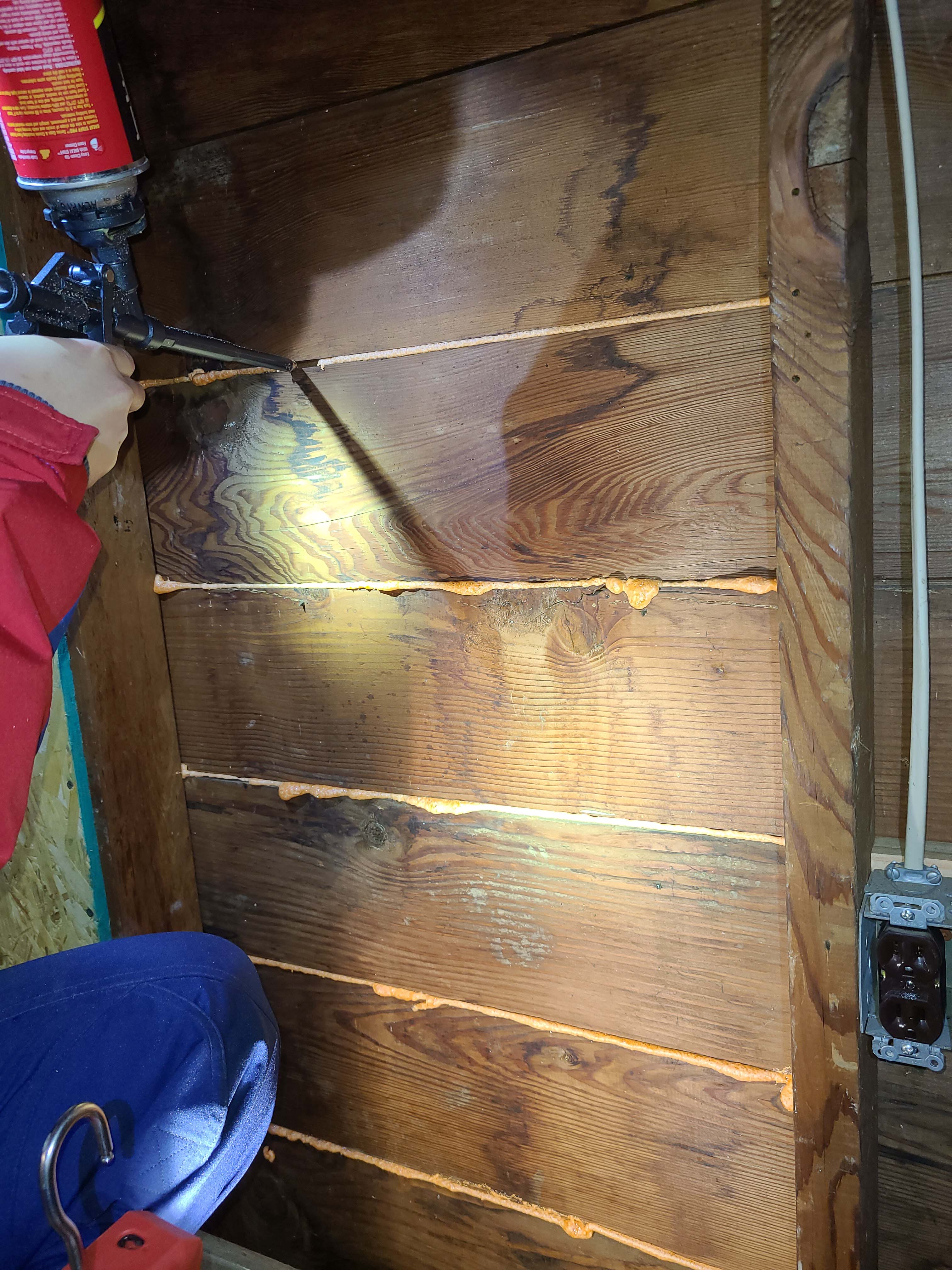
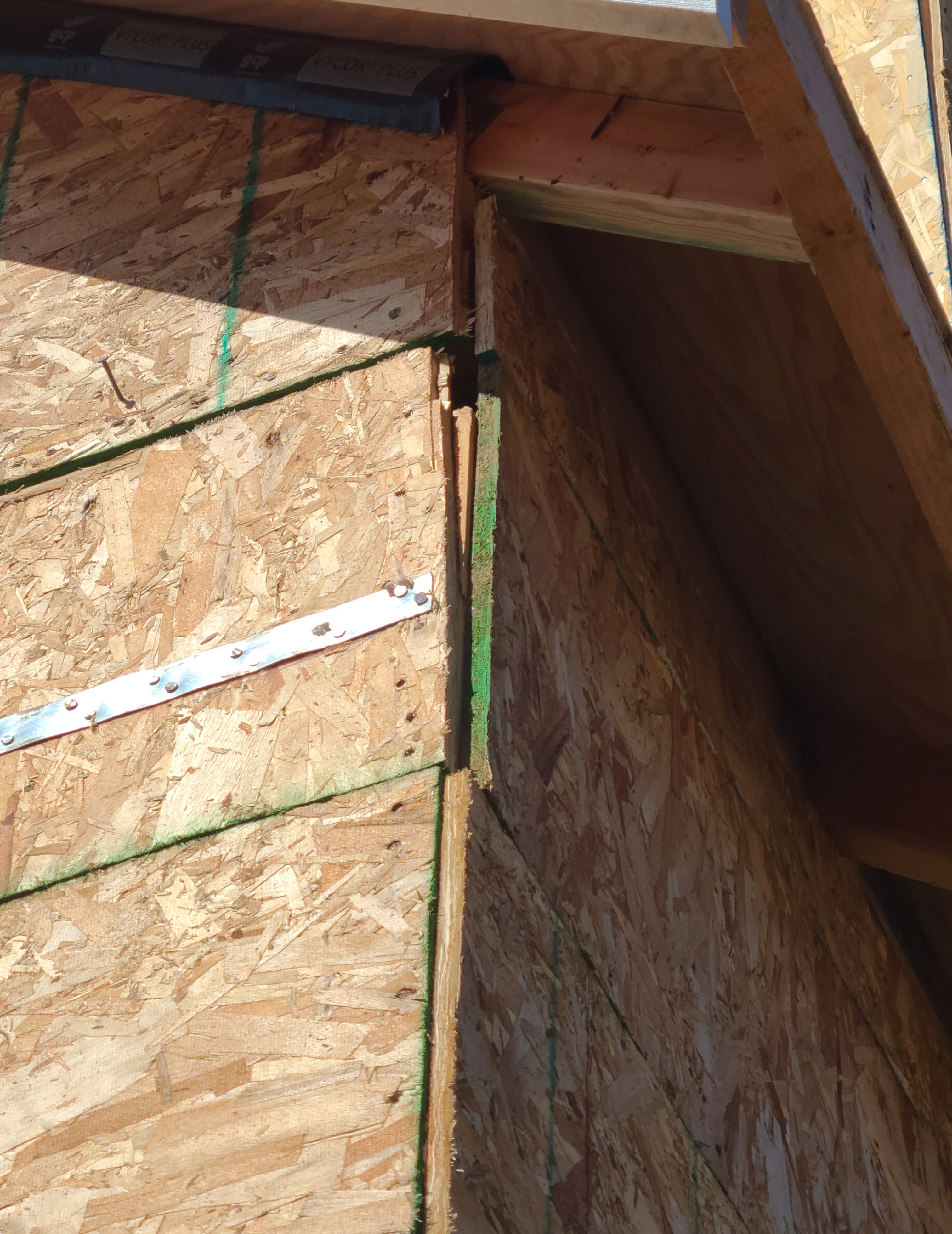
- Seal all mechanical penetrations in exterior walls using a compatible tape as shown in Figure 4. If the gap around the pipe is larger than ½ inch, it can be filled from the inside with spray foam that is trimmed flush on the outside then covered with tape.
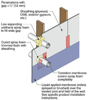
Figure 4. Use flashing tape to seal around any pipes or vents that penetrate through the foam sheathing. Tape should be applied in an overlapping, shingle fashion. Use a flashing product that is compatible with the foam. Windows and Doors
These instructions describe how to install foam sheathing around a window when no house wrap or OSB structural sheathing is used (for more on these instructions and additional instructions on installing foam on walls that have OSB sheathing, see BSC 2007). Three methods for installing windows in walls with rigid foam are also described in the standard practice document "FMA/AAMA/WDMA 500-16, Standard Practice for the Installation of Mounting Flange Windows into Walls Utilizing Foam Plastic Insulating Sheathing (FPIS) with a Separate Water-Resistive Barrier.” This guide describes the following methods a) (where the foam is applied directly to the sheathing and house wrap ins installed over the foam using the following sequence) window buck; insulating foam; house wrap (WRB); sill flashing; window; jamb flashing; head flashing; head tape. A2) (house wrap is applied after the window is installed) the sequence is: window buck; insulating foam; skirt; sill flashing; window; jamb flashing; head flashing; house wrap (WRB); jamb tape; head tape. The window buck can be wood or a prefabricated rigid foam product. B) the window is installed into the window buck over the house wrap, and the foam insulation is applied next. This method uses either fluid-applied or peel-and-stick flashing. or C) the house wrap and the window are installed in the wall before the foam is applied; in this case, there’s no window buck (FMA, AAMA, WDMA 2016).
- Install foam sheathing up to rough framing on frame wall.
- Install a back dam on the window sill to prevent any water that leaks around frame from running to the interior.
- Install adhesive-backed sill flashing in one piece if flexible or in two pieces as shown if not flexible. Install corner flashing patches at sill if not using flexible flashing.
- Install adhesive-backed jamb flashings (jamb flashing is adhered to foam and stapled to frame).
- Apply sealant at jambs, head and sill. Alternatively, sealant can be applied to the back side of the nailing flange (sealants, house wraps, and flashings must be chemically compatible).
- Install window plumb, level, and square as per manufacturer’s instructions.
- Install jamb flashing.
- Install drip cap (if applicable). Install head flashing. Tape head flashing. Air seal around the perimeter on the interior with sealant or low-expanding foam.
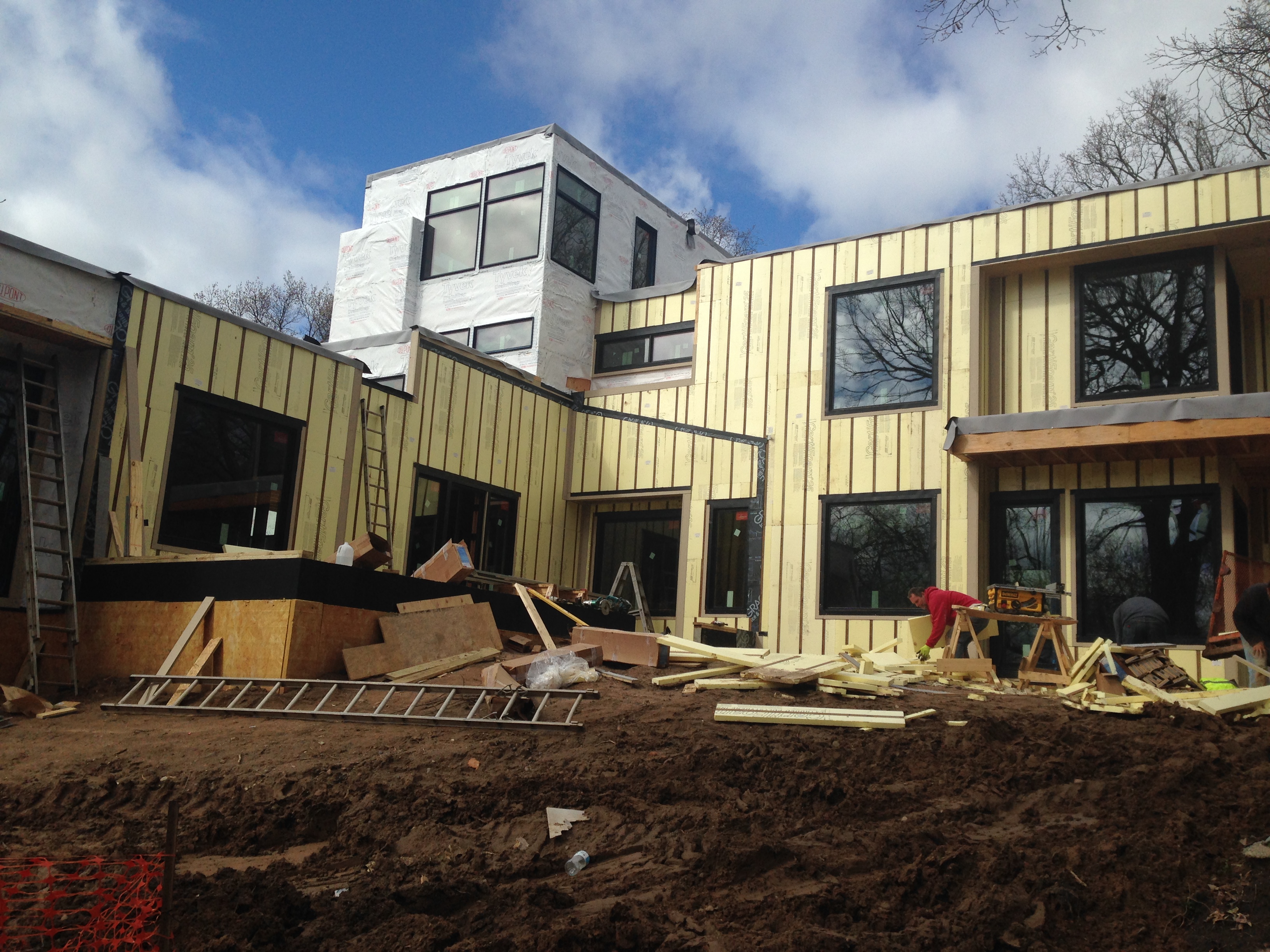
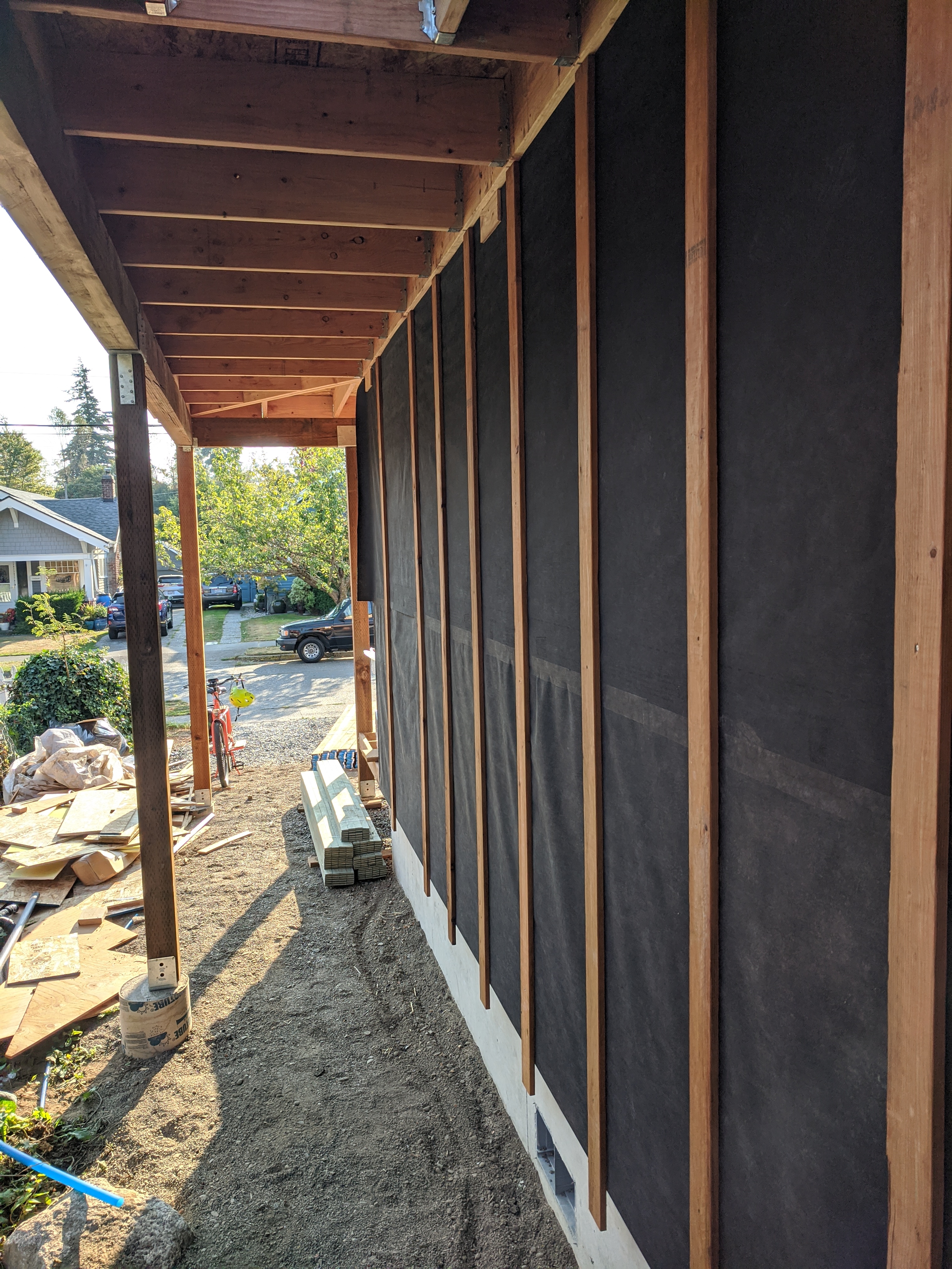
- Furring
- Determine the appropriate fastener for the project’s wind-load requirements.
- Select the appropriate furring (strapping) material. For metal framing, use metal furring that is at least 20 gauge metal. For wood framing, use 1x4 lumber. The wood furring specific gravity should be equivalent to typical reference wood stud specific gravity.
- Locate the framing members by transferring the frame layout directly from the wall framing to each attachment of rigid foam insulation or snap vertical chalk lines onto the foam insulation at each stud location after foam has been installed. (Some foam products may be available with pre-marked fastener lines.)
- Install the furring strips (strapping) over the foam following the installation guidance provided by the furring fastener manufacturer (or the Foam Sheathing Coalition). The fastener must fully engage the framing or stud. Install fasteners prior to utilities to avoid potential damage. Correct any irregularities and unevenness in framing, sheathing, foam and other wall assembly components, including under driven nails, as these can telegraph through to the finished siding and trim. Avoid overdriving fasteners but make snug enough to remove gaps between the connected parts.
- When installing trim on inside corners, outside corners, and around wall penetrations (e.g., windows, doors, vents), use a wider furring strip if needed to accommodate the trim width and accommodate the wall framing offset that the foam thickness creates.
- An insect screen should be installed at the top and bottom of the furring strips. Place it on the insulated sheathing where the strips will start and end. After the strips are installed, fold the screen over the strip ends and fasten to the top surface of the furring before installing the cladding.
Cladding
There are many types of cladding. Wood lap fastening is described below as an example (WRCLA 2012). Follow your specific cladding manufacturer’s recommendations.
- Choose a siding pattern with narrower boards (8 inches or less) that are thicker. Thick, narrow siding is more stable than thinner, wider patterns and better able to resist dimensional changes. Use kiln-dried siding for more dimensional stability.
- Before installing siding, back prime all surfaces of wood siding (including ends) with 100% acrylic-latex primer that is allowed to cure above 50°F. Prime all field cuts. The end grain of all wood products absorbs liquid up to 250 times faster than other wood surfaces.
- Pre-drill holes at mitered corners, near edges and near ends to avoid splitting, if needed.
- Make sure the fastener length satisfies the wind pressure ratings requirements for your area.
- For wood studs:
- For foam sheathing up to 1 inch thick, add the foam thickness to the code-required fastener length to penetrate the framing by at least one inch.
- For foam sheathing 1.25 to 1.5 inches thick, add the thickness of the sheathing to the fastener length to determine adequate length to penetrate the wood stud by a minimum of 1.25 inches.
- For metal studs (with screws):
- For foam sheathing up to 1.5 inches thick, use #8 screws that penetrate through the 20-gauge metal studs by 3 full threads; the screw head diameter shall be as required to meet code without the sheathing thickness.
- For foam sheathing that is more than 1.5 inches thick, use furring strips:
- Attach siding to furring strip with nails spaced at a maximum of 24 inches on center.
- For wood studs:
- Fasten each piece of siding independently. Do not nail overlapping pieces together as this restricts the natural movement of each piece and may cause splitting.
- Apply fasteners snug to surface but avoid overdriving fasteners, which can result in dimpling of the siding due to the compressible nature of the foam sheathing. Heavy nailing distorts the wood and may cause splitting. Hand nailing is preferred. Avoid the use of pneumatic nailers, if possible. If a pneumatic nailer must be used, reduce the air pressure and tap nails flush.
- Fill overdriven nail holes with exterior-grade wood putty specifically designed for filling exterior nail holes.
- Use light-colored finish coats to maximize heat reflection and reduce dimensional movement.
How to Install Insulated Siding (Vinyl Siding Institute 2012)
Always consult the manufacturer’s instructions, but the following general insulated siding installation instructions apply:
- A water-resistive barrier should be installed under all insulated siding. Insulated siding is not a watertight covering. It functions as an initial barrier to rain and reduces the amount of water that reaches the underlying water-resistive barrier.
- Be sure to use accessories that will accommodate the full thickness of the insulated siding. Consult the manufacturer’s instructions for specific accessories (e.g., J-channel, corner posts) or techniques that work best with a given product. Use the starter strip specified by the insulated siding manufacturer to ensure proper performance.
- When installing a panel, it is critical that the lock is fully engaged with the piece below it. Without stretching the panel, reach up and fasten it into place.
- On the factory-cut ends of insulated siding panels, the foam is set back from both ends of the panel. This set-back is required to ensure correct overlapping of adjacent panels. To correctly overlap the panels, insert the vinyl tab at the end of one panel in between the foam and the vinyl of the adjacent panel. Slide the panels together until the ends of the foam touch. It is recommended to have a gap of 1/8” during installation under cold weather conditions (i.e., 40°F or 4.4°C). For best appearance, lap factory ends only. If you must lap a non-factory end, create the required foam set-back and siding panel notches following the siding manufacturer’s instructions.
- When determining the length of the final panel of a course, measure from the edge of the foam on the installed panel to the corner, allowing 1/4” for expansion. Apply this measurement to the final panel, measuring the foam instead of the panel. This will ensure foam-to-foam contact, with the necessary amount of room for expansion of the siding.
- Using a circular saw with the fine-toothed plywood blade turned backwards, cut slowly with the vinyl face up. Be sure to cut all the way through the foam.
- Avoid using panels shorter than 24 inches long.
- When cutting insulated siding, use a circular saw with a fine-toothed (plywood) blade inserted backwards and cut slowly with the vinyl face up. Be sure to cut through the frame. Do not attempt to cut materials other than vinyl siding or insulated siding with a reversed direction saw blade.
- Fasten nails or other fasteners in the center of the nailing slot; make sure the fastener penetrates a minimum of 3/4” into framing, furring or another approved nailable surface. Do not drive the head of the fastener tightly against the siding nail hem; allow approximately 1/32”clearance (the thickness of a dime) between the fastener head and the vinyl siding. Consult manufacturer’s instructions for fastener specifications.
- Around windows and doors, because insulated siding is thicker than vinyl siding, use wood shims and either aluminum trim coil or vinyl lineals to build out door and window openings if needed.
- To complete the final course of insulated siding at the top of a wall, take the height measurement of the remaining open section in several locations and subtract 1/4” from each location to allow for movement. Cut the panel to the required measurement and cut back the foam 2 inches. Using a snap lock punch, punch the vinyl siding along the cut edge every 6 inches, so the raised lug is on the outside face. Install utility trim along the top of the wall to receive the top edge of the siding. Use shims under the utility trim to match the angle or distance from the wall of the siding edge. Push the siding into the utility trim. The raised lugs will catch and hold the siding firmly in place.
Ensuring Success
The HERS rater will inspect to determine if the total amount of wall insulation installed meets the minimum R-value requirement for the climate where the house is located. The rater should also verify that the wall is designed to provide adequate shear resistance if the foam insulation also serves as the exterior sheathing.
Typical R-values for common insulation materials are summarized in this table, which also identifies the vapor retarder classification for each insulation.
Region
Insulation levels should meet or exceed the minimum levels specified in the applicable building code for the home's location and climate zone.
The map in Figure 1 shows the climate zones for states that have adopted energy codes equivalent to the International Energy Conservation Code (IECC) 2009, 12, 15, and 18. The map in Figure 2 shows the climate zones for states that have adopted energy codes equivalent to the IECC 2021. Climate zone-specific requirements specified in the IECC are shown in the Compliance Tab of this guide.

Source
2012 edition of code establishing a baseline for energy efficiency by setting performance standards for the building envelope (defined as the boundary that separates heated/cooled air from unconditioned, outside air), mechanical systems, lighting systems and service water heating systems in homes and commercial businesses.

Source
2021 edition of code establishing a baseline for energy efficiency by setting performance standards for the building envelope (defined as the boundary that separates heated/cooled air from unconditioned, outside air), mechanical systems, lighting systems and service water heating systems in homes and commercial businesses.
Rigid insulation sheathing can provide a vapor-resistant layer, depending on the thickness and whether the foam is open cell or closed cell. As a general rule for framed construction, the vapor-retarding layer should be placed in the interior of the assembly in cold climates (to prevent water vapor from the higher humidity interior air from diffusing into the assembly). In hot, humid climates, the vapor-retarding layer should be placed to the exterior of the assembly to prevent moisture-laden outside air from coming into contact with the back surface of the interior wall, which may have a temperature below the dew point of the air, resulting in condensation on the interior wall. Year-round dew point temperatures should be taken into account when designing the building’s wall assemblies.
Training
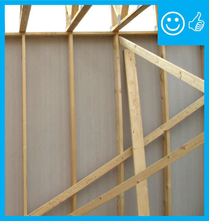
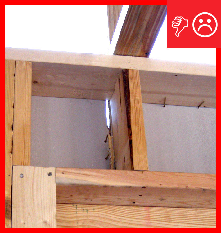
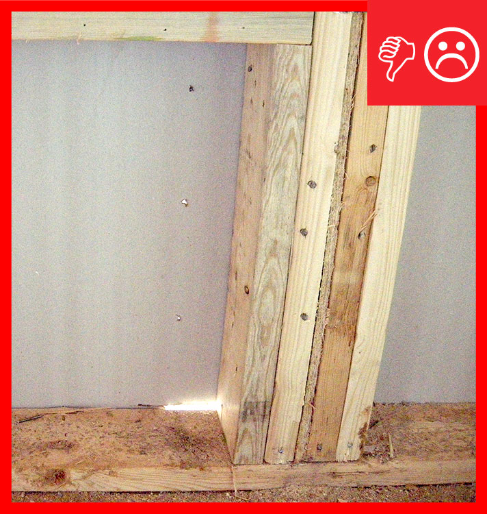
Right and Wrong Images

Source
Guide describing details that serve as a visual reference for each of the line items in the Thermal Enclosure System Rater Checklist.
Source
Guide describing details that serve as a visual reference for each of the line items in the Thermal Enclosure System Rater Checklist.

Source
Guide describing details that serve as a visual reference for each of the line items in the Thermal Enclosure System Rater Checklist.
Source
Source
Source
Source
Source
Source

Source
Source
Source
Source
Source
Source
Source
Source
Source
Source
Source
Source
Source
Source
Source

Source
Source
Source
Source
Source
Source
Source

Source
Source
Source
Source
Source
Source

Source
Source
Videos


Compliance
More Info
Case Studies
References and Resources
*For non-dated media, such as websites, the date listed is the date accessed.
Contributors to this Guide
The following authors and organizations contributed to the content in this Guide.
Building Science Corporation, lead for the Building Science Consortium (BSC), a DOE Building America Research Team
Sales
Exterior Insulation Sheathing = Continuous Exterior Thermal Blanket
Technical Description
Wood framing accounts for 24% of conventionally framed walls and 14% of advanced-framed walls. This represents a large thermal hole since wood has about one-fourth the thermal resistance of most insulation materials. This problem is effectively addressed with a continuous thermal blanket of rigid foam installed on the exterior of the walls, either over the sheathing or in place of the wood sheathing. Advantages include blocking heat transfer through the studs, reducing drafts, and minimizing the risk of moisture problems by shifting condensation temperatures outside of the framing cavity.
Questions? Comments? Contact our webmaster.