

Scope
Design a mechanical ventilation system where airflow can be measured safely and accurately.
- Plan a specific location where outdoor ventilation airflow can be accessed and measured safely.
- In cases where a ventilation terminal or grille is inaccessible, provide an inline airflow station or long, rigid, straight duct section in an accessible location. A long, straight section of rigid duct can be used to measure air velocity and calculate airflow rate.
- Install labels that indicate the origin of ventilation air and direction of flow onto key components of whole house mechanical ventilation (WHMV) systems. Examples include grilles, ducts, flow stations, dampers, and at equipment connections. Labels should also be located at mechanical ventilation controls or switches.
- Specify mechanical equipment capable of delivering ventilation flowrates meeting all relevant codes and standards (e.g., ASHRAE 62.2).
- Design ducts to limit static pressure and airflow restriction using short, direct, adequately sized ductwork and smooth radius bends.
- Provide adequate structural support to entire duct system.
- Apply mastic, mastic plus embedded fiberglass mesh fabric, or UL 181A/B tape to seal all duct connections including ducts to grilles.
For an overview of whole-building ventilation systems and airflow requirement guidelines, see the Building America Solution Center guides Whole-House Ventilation Strategies for New Homes and Whole House Ventilation Strategies for Existing Homes.
See the Compliance tab for links to related codes and standards and voluntary federal energy-efficiency program requirements.
Description
Air flow in ventilation systems can be measured using any of several methods described in the Building America Solution Center guide “Measuring Mechanical Ventilation Airflow.” However, getting access to the system to test it can be challenging. This guide describes methods for ways to access the ventilation equipment for testing.
Verifying the delivery of adequate whole-house mechanical ventilation (WHMV) is critical to the health of occupants. Studies in different parts of the country have consistently shown that homes with WHMV systems often fail to deliver adequate ventilation (Sonne et al. 2016, Eklund et al. 2014, and Lubliner et al. 2002). Poor design of the WHMV system is one of many common causes of inadequate ventilation.
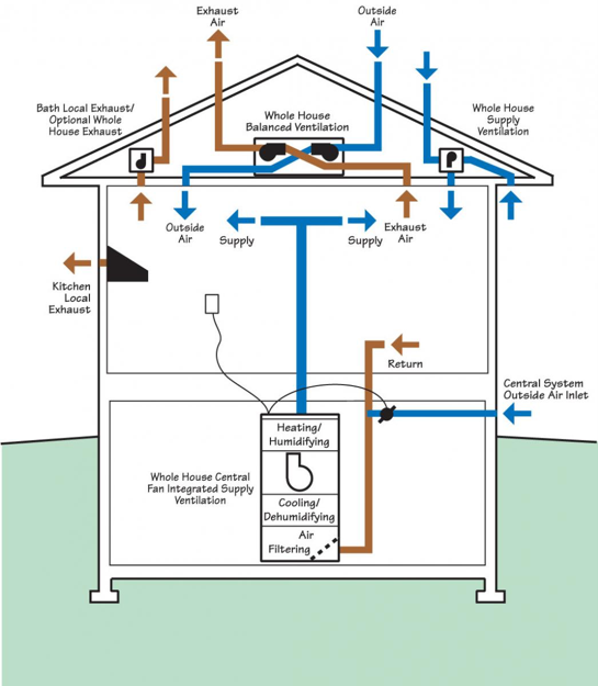
Energy conservation efforts have resulted in tighter homes with better control over air leakage, leading to reduced natural ventilation to the point where WHMV is needed to ensure adequate indoor air quality. WHMV can be provided through four approaches: 1) exhaust only, 2) supply only, 3) central fan integrated supply (CFIS) (a form of supply only), and 4) balanced, which includes energy recovery ventilators (ERV) or heat recovery ventilators (HRV). See Figure 1.
More details including the pros and cons of these different systems can be found in the Building America Solution Center guide: Whole-House Ventilation Strategies for Existing Homes.
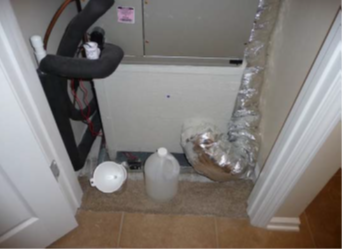
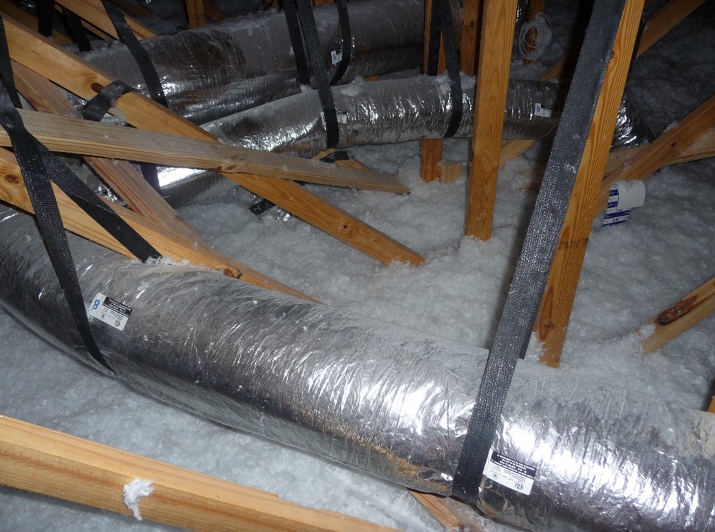
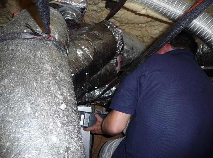
One fundamental limitation imposed on WHMV is lack of architectural and mechanical planning. Based upon past observations, where and how to install a specific WHMV is not likely to be part of architectural planning. Rather, mechanical contractors are usually tasked to make a ventilation system fit within whatever space is available. This lack of planning decreases the likelihood that properly sized ventilation equipment can be installed without compromises that reduce intended airflow rates. A common example is where long duct runs with numerous turns are required to get around structural components or when ducts must be kinked or compressed to fit between structural components (Figure 2).
Design Ventilation System to Allow for Good Air Flow and Access to Measurement Locations
Specify mechanical equipment capable of delivering ventilation flowrate meeting all relevant codes and standards (e.g., ASHRAE 62.2, see guides in step 1). Create a WHMV dimensioned plan layout early in the building design phase so that the building design can accommodate the WHMV design. Follow best practice duct installation, minimizing bends and cut lengths and providing adequate duct support and proper duct sealing (see Sealed and Insulated Flex Ducts, Sealed and Insulated Metal Ducts, and No Kinks or Sharp Bends in Flex Duct Installation. Designate a specific location on the WHMV layout plans where airflow measurements can be made.
Measuring Air Flow at the Grille
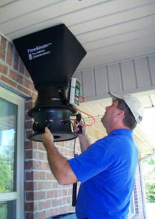
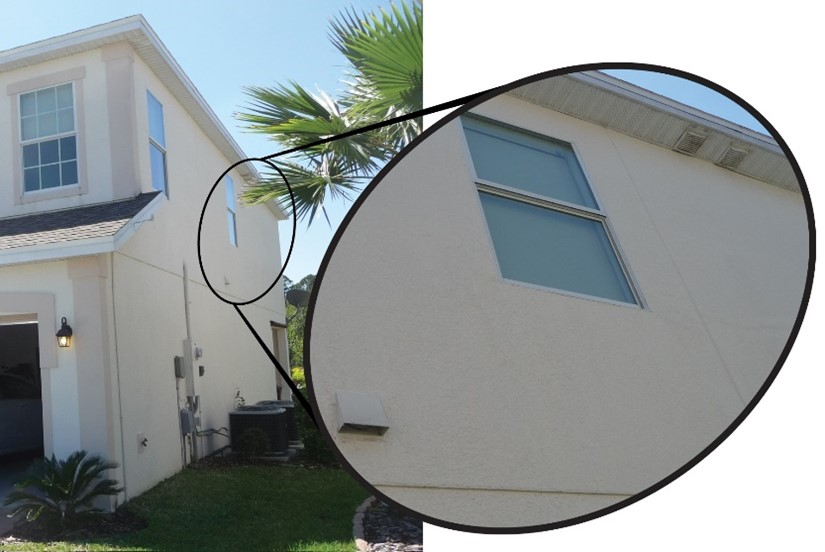
Airflow measurements can be taken at inlet or exhaust grilles located indoors or outdoors, often in a roof soffit, porch roof, or on an exterior wall (Figure 3). Indoor grilles are less prone to wind-induced measurement errors. However, this may not be an option. When flow is to be measured at outdoor grilles, there must be reasonably safe access to them. Outdoor air intakes and exhaust outlets are often located in roof soffits or porch ceilings requiring the use of a ladder to access the grille to take measurements.
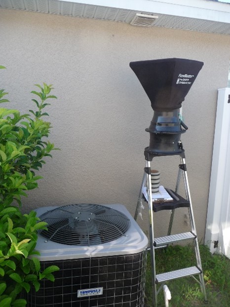
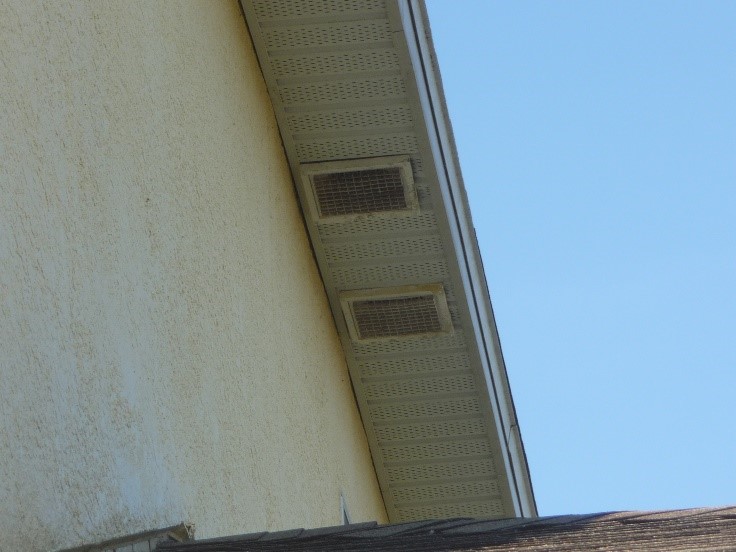
Airflow at the intake/exhaust grille is often measured with a flow hood that requires two hands to hold the hood firmly in place while taking measurements, making it difficult to hold onto the ladder at the same time. Grilles located only one story above ground are fairly safe for experienced practitioners to make measurements from a ladder. However, it would not be safe to take measurements at intake grilles located higher than one story (Figures 4 and 5).
Measuring Air Flow at a Testing Station in the Duct
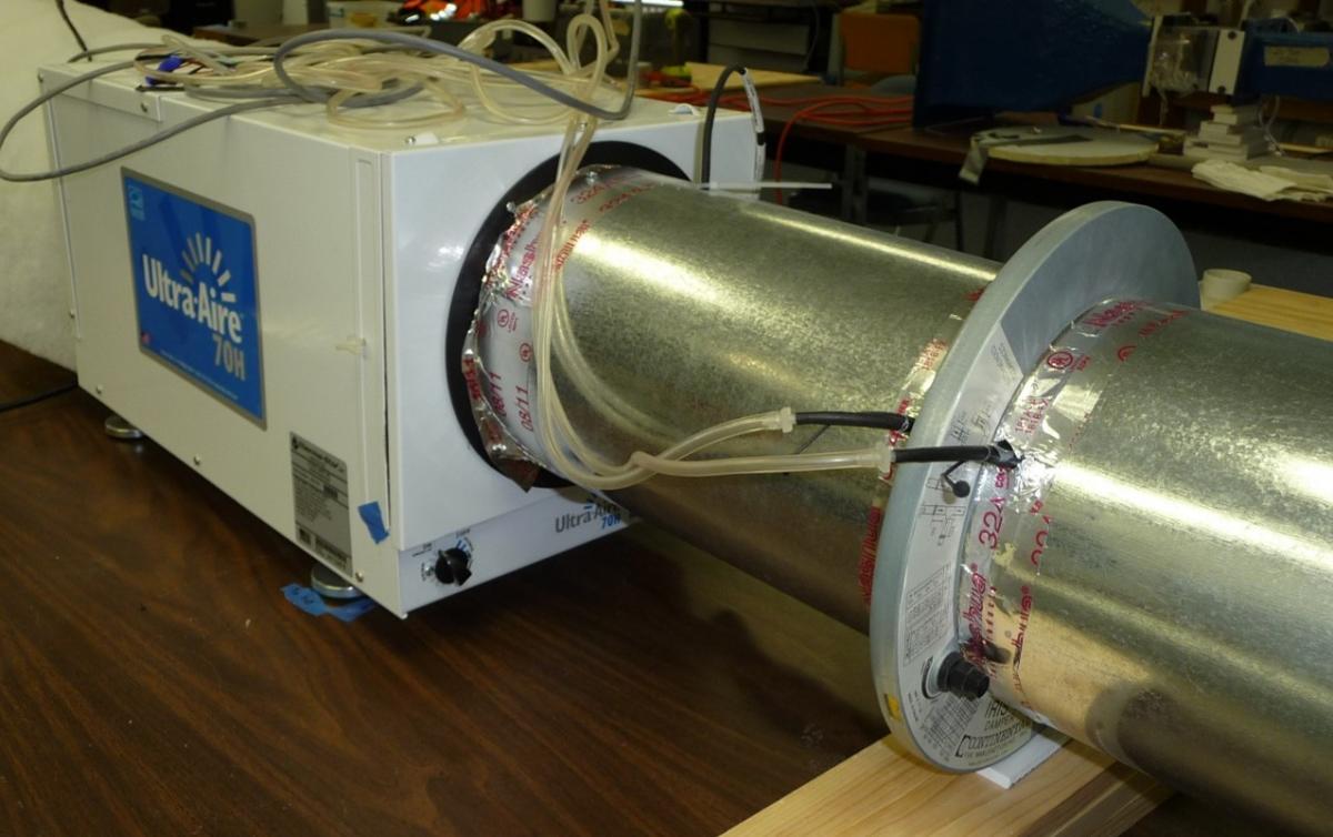
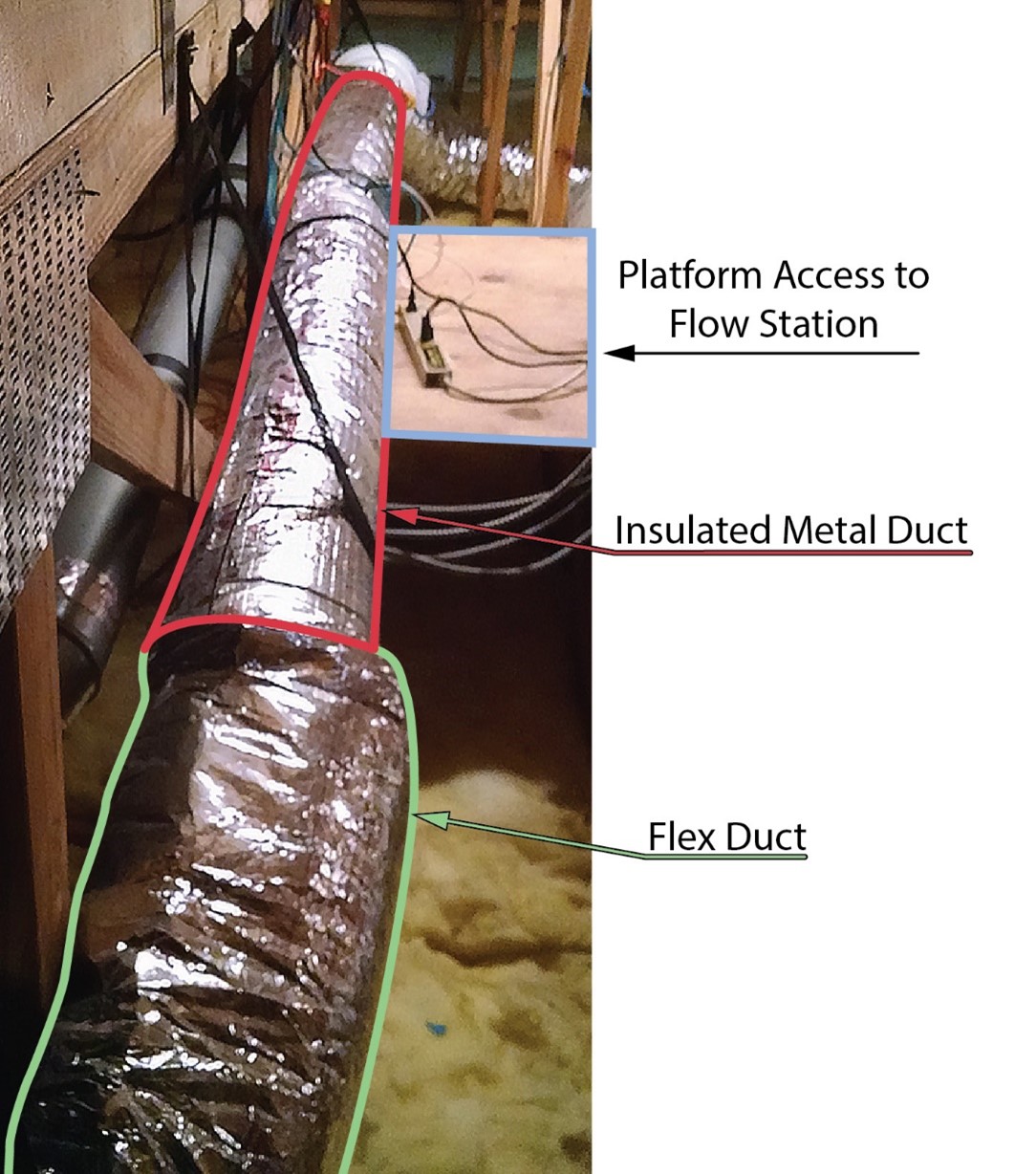
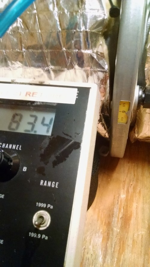
In cases where a ventilation terminal or grille is inaccessible, if there is a long, rigid, straight duct section in an accessible location, an “inline airflow station” can be installed to serve as a spot where air velocity can be measured to calculate airflow rate. See an example of a testing station in Figure 6.
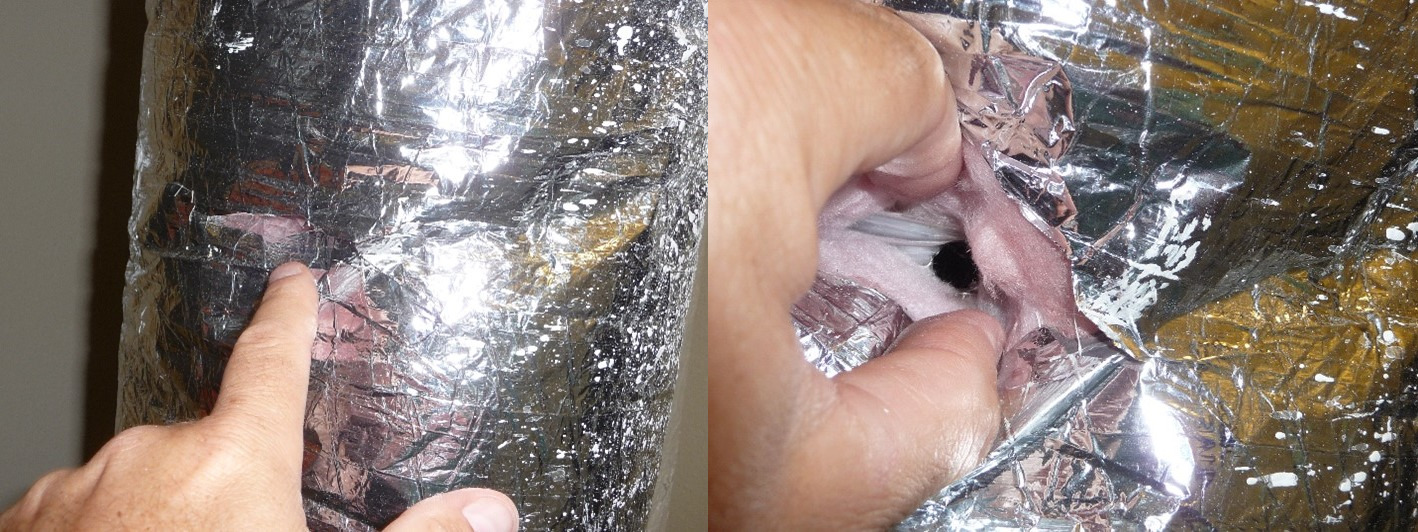
Measuring Air Flow at a Hole in the Duct
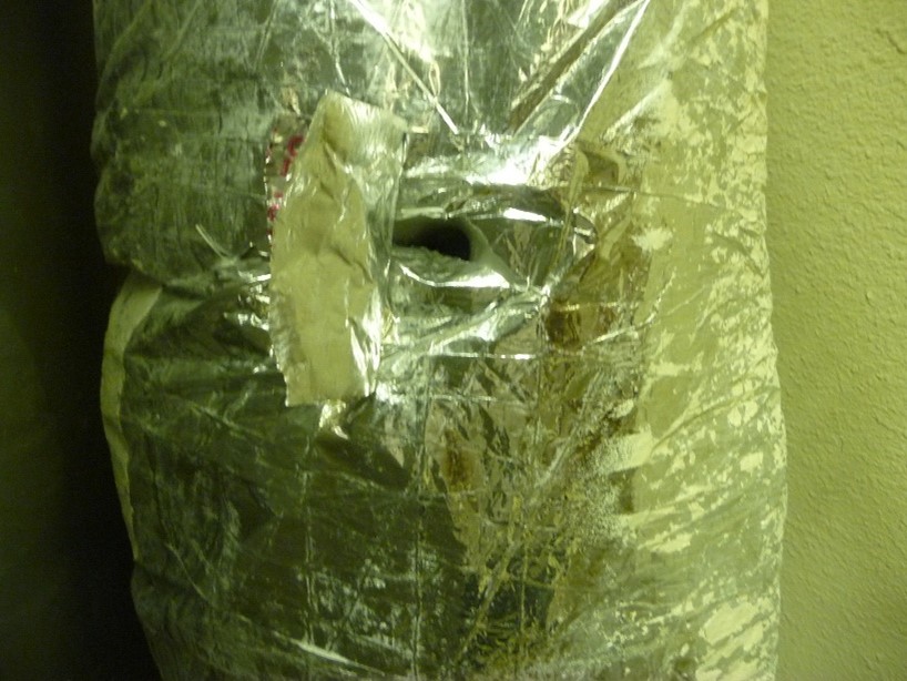
If there are no terminal grilles that are accessible, and if there is no in-line air flow testing station installed, another option for measuring air flow in the air intake ducts is to make a small hole in the duct to measure airflow (see Figure 7). This option will only work in instances where the duct is made of a smooth rigid material and where a long straight section of duct is accessible. Flex duct or duct sections with bends or elbows will not work because the turbulence caused by flex duct corrugations or bends will cause measurement errors. Seal the hole after testing; replace insulation if any was removed and seal the vapor barrier over the duct insulation as well.
Label System Components
Provide labels indicating the origin of the ventilation air and direction of flow on key components of the WHMV system (e.g., grilles, ducts, flow stations, dampers, equipment connections). Labels are especially important for more complex WHMV systems. For instance, an energy or heat recovery ventilator typically has four ducts. Thermal conditions are transferred from the indoor air to the outdoor air to minimize energy. This requires one duct to deliver outdoor air into the unit which then gets transferred to a second duct that delivers outdoor into the home. A third duct pulls air out of the house, like an exhaust fan, transfers the air to the air exchanger and then sends it to outdoors through a fourth duct. Without labels, one must go to the recovery ventilator to determine where air is coming from or going to. Even after doing this, it can be difficult to track ducts to terminals.
How to Design Mechanical Ventilation that Will Allow Effective Airflow Measurement Verification
- Choose a WHMV strategy designed for safe, effective flowrate measurements. A number of strategies are available based on climate, construction, and budget among other factors (details in Whole-House Ventilation Strategies for New Homes and Whole House Ventilation Strategies for Existing Homes guides.
- Specify mechanical equipment capable of delivering ventilation flowrate meeting all relevant codes and standards (e.g., ASHRAE 62.2, see guides in step 1).
- Create a WHMV dimensioned plan layout early in the building design phase so that the building design can accommodate the WHMV design.
- Follow best practice duct installation, minimizing bends and cut lengths and providing adequate duct support and proper duct sealing (see Sealed and Insulated Flex Ducts, Sealed and Insulated Metal Ducts, and No Kinks or Sharp Bends in Flex Duct Installation).
- Designate a specific location on the WHMV layout plans where airflow measurements can be made.
- If a ventilation grille is difficult to access, provide an inline airflow measurement station in an accessible location. A straight section of rigid ducting should allow for sufficient air velocity measurement and accurate airflow rate calculation.
- Provide labels indicating the origin of the ventilation air and direction of flow on key components of the WHMV system (e.g., grilles, ducts, flow stations, dampers, equipment connections).
- Clearly label any WHMV controls that are not obviously identified (see the guide Obvious Ventilation Controls).
Ensuring Success
The building architect must communicate with the mechanical contractor during design planning to accommodate space requirements for the WHMV system before the final construction plan is drawn.
The construction plans should identify at least one location allowing safe access to air grilles or an installed airflow station where the ventilation flow rate can be measured. For example, grilles located on soffits above one story high are not safe. Find another, safer location for testing.
The mechanical contractor/engineer will:
- Select appropriate ventilation equipment for the designed static pressure based on standard codes/guides.
- Size ducts correctly to ensure adherence to design static pressures.
- Plan on the most direct duct layout (i.e., minimizing bends and duct lengths) to enable the design ventilation rate to be delivered into home.
Region
No climate-specific information applies.
Training
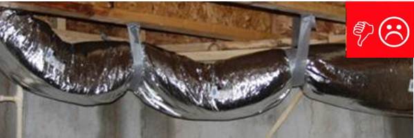
Right and Wrong Images
Compliance
Ventilation code requirements referenced in ASHRAE, IECC and IRC codes are discussed in the compliance tab of the Whole House Ventilation Strategies for Existing Homes guide.
Ventilation requirement for new home programs including the DOE Zero Energy Ready Home Program, EPA Indoor airPLUS, and ENERGY STAR Certified Homes are discussed in some detail in the compliance tab of the Whole-House Ventilation for New Homes guide.
Retrofit
Guidance for the measures described in this guide is applicable to both new and existing homes.
For more information on assessing existing ventilation systems, see the Solution Center information guide Pre-Retrofit Assessment of Ventilation Systems.
See the Solution Center guide Whole House Ventilation Strategies for Existing Homes for an extensive discussion on the topic.
More Info
References and Resources
*For non-dated media, such as websites, the date listed is the date accessed.
Contributors to this Guide
The following authors and organizations contributed to the content in this Guide.
Questions? Comments? Contact our webmaster.