

Scope
When installing a concrete slab on a crawlspace floor, install a capillary break of polyethylene sheeting over the ground before pouring the slab.
- Use ≥6-mil polyethylene sheeting.
- Lap any seams in the sheeting by 6-12 inches and seal the seams with a continuous bead of acoustical sealant, butyl rubber, or butyl acrylic caulk, or with tape manufactured to seal or patch polyethylene.
- Seal the sheeting around posts or pipes coming up from the ground and at walls to provide a continuous vapor barrier.
See the Compliance Tab for links to related codes and standards and voluntary federal energy-efficiency program requirements.
Description
When constructing a home with a crawlspace, some builders will pour a concrete slab on the crawlspace floor, which can facilitate use of the crawlspace for storage or ease in accessing HVAC equipment that may be installed in the crawlspace. This thin slab, typically 2 to 4 inches thick, is sometimes referred to as a "rat slab" in reference to its resistance to penetration from burrowing rodents. It is important to keep in mind that a concrete slab alone will not prevent moisture from coming up into the crawlspace from the surrounding ground. Porous materials like concrete, wood, or masonry block can wick moisture upward through tiny cracks and pores via capillary action for surprisingly long distances. Capillary action in concrete is theoretically capable of pulling water upwards up to 6 miles (Lsibturek, 2014).
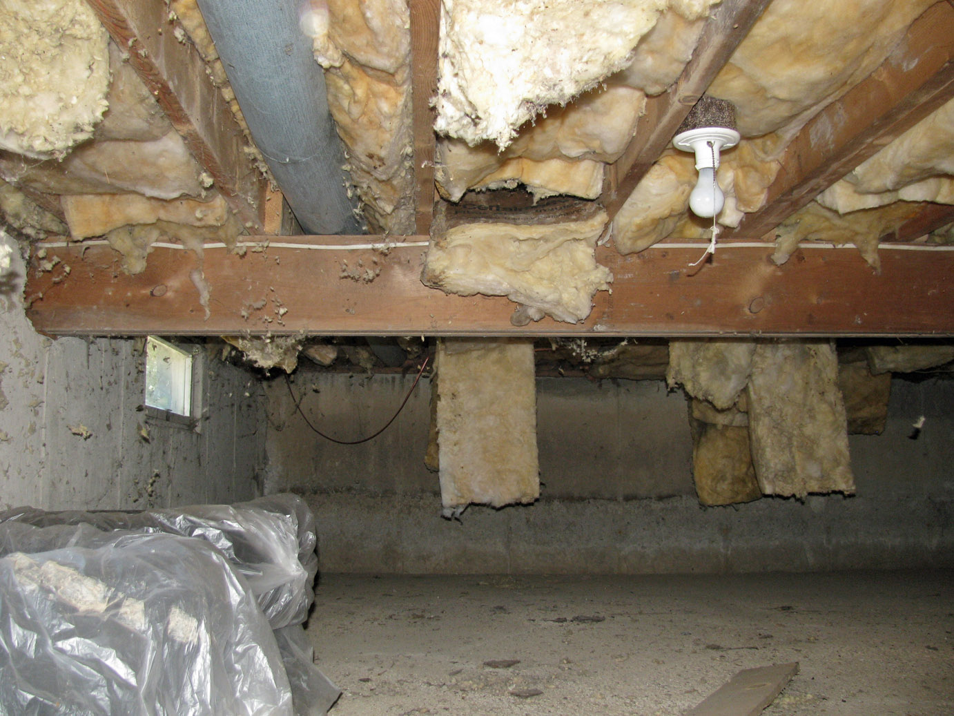
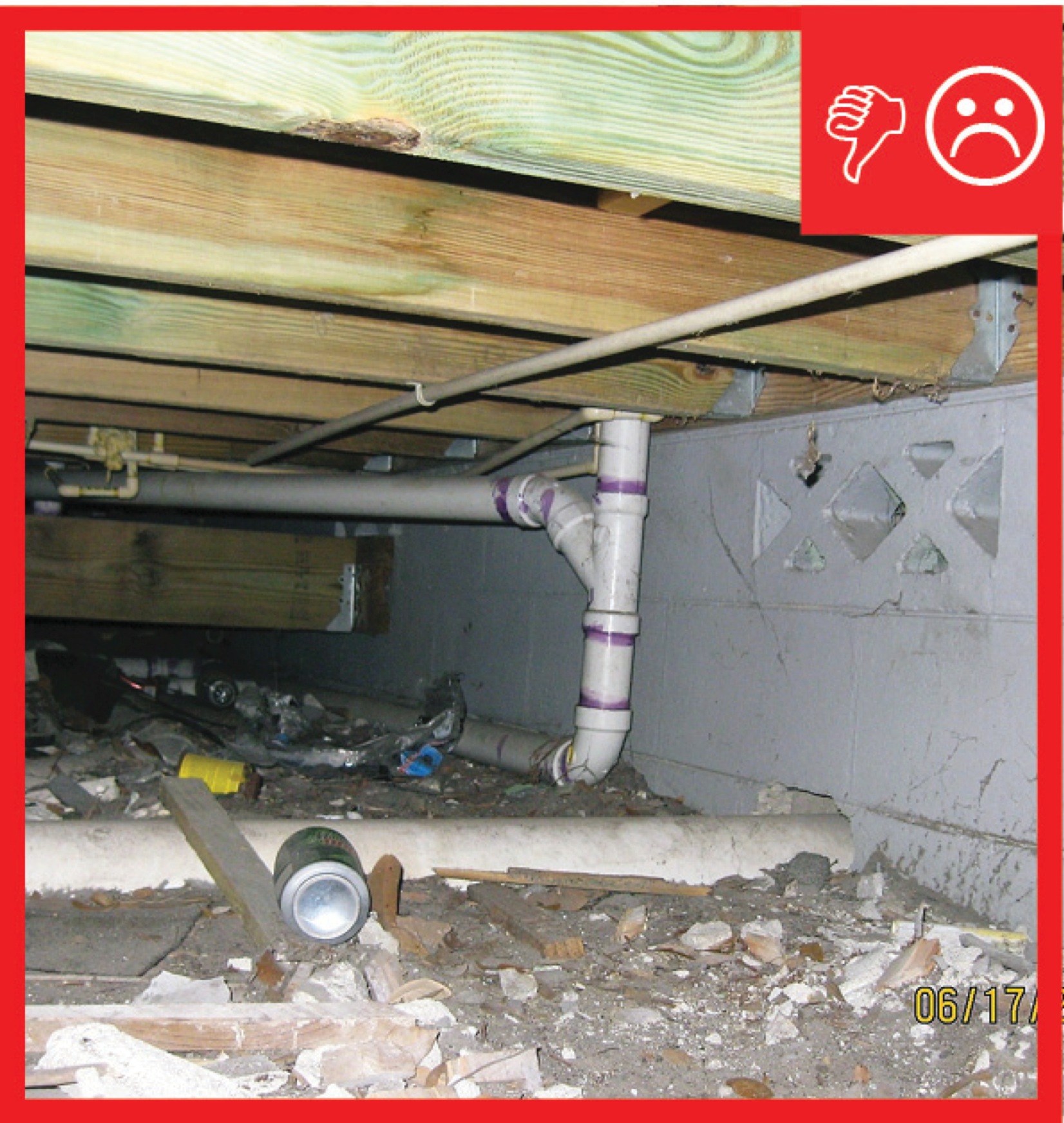
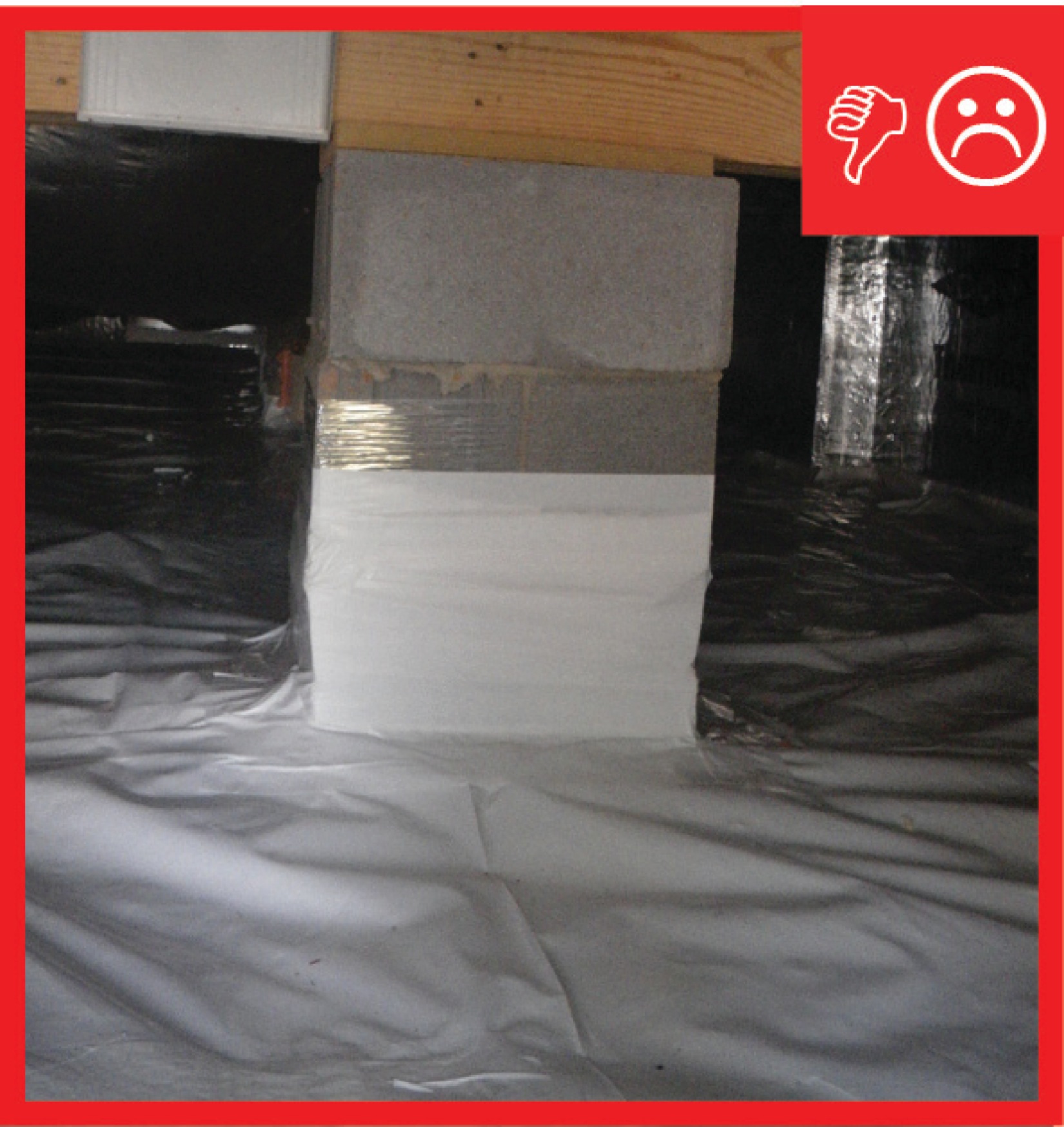
Without a capillary break, moisture can wick up through the pores of a concrete slab and enter the crawlspace, which can lead to mold and the moisture-related failure of building materials. Also, the air exchanged between the moisture-laden crawlspace and the house can carry mold and contaminants into the home; this exchange is intensified when leaky forced-air heating and air-conditioning ducts are located in the crawlspace (see Figure 1) (EPA Indoor AirPlus). (Note, best practice in most climates is to seal and insulate the crawlspace if installing HVAC equipment there. See the guide Unvented, Insulated Crawlspaces for more information.)
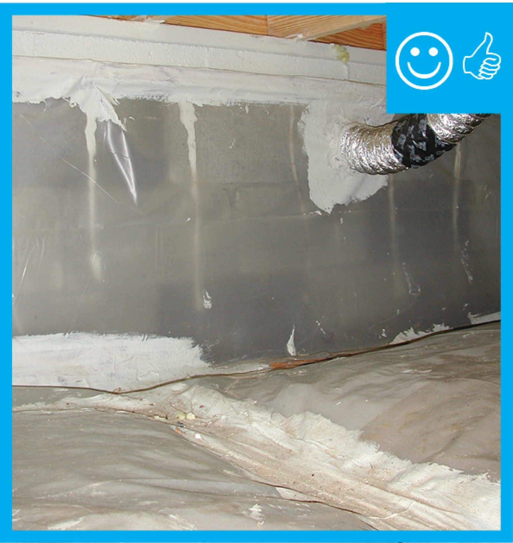
To stop the migration of water from the ground into the crawlspace via capillary action, the builder should install a capillary break consisting of a water-impermeable material such as polyethylene sheeting under the slab. This can be installed over a material like gravel that also breaks capillary action due to the large spaces between the rocks, as discussed in the guide Capillary Break beneath Slab - Polyethylene Sheeting or Rigid Insulation.
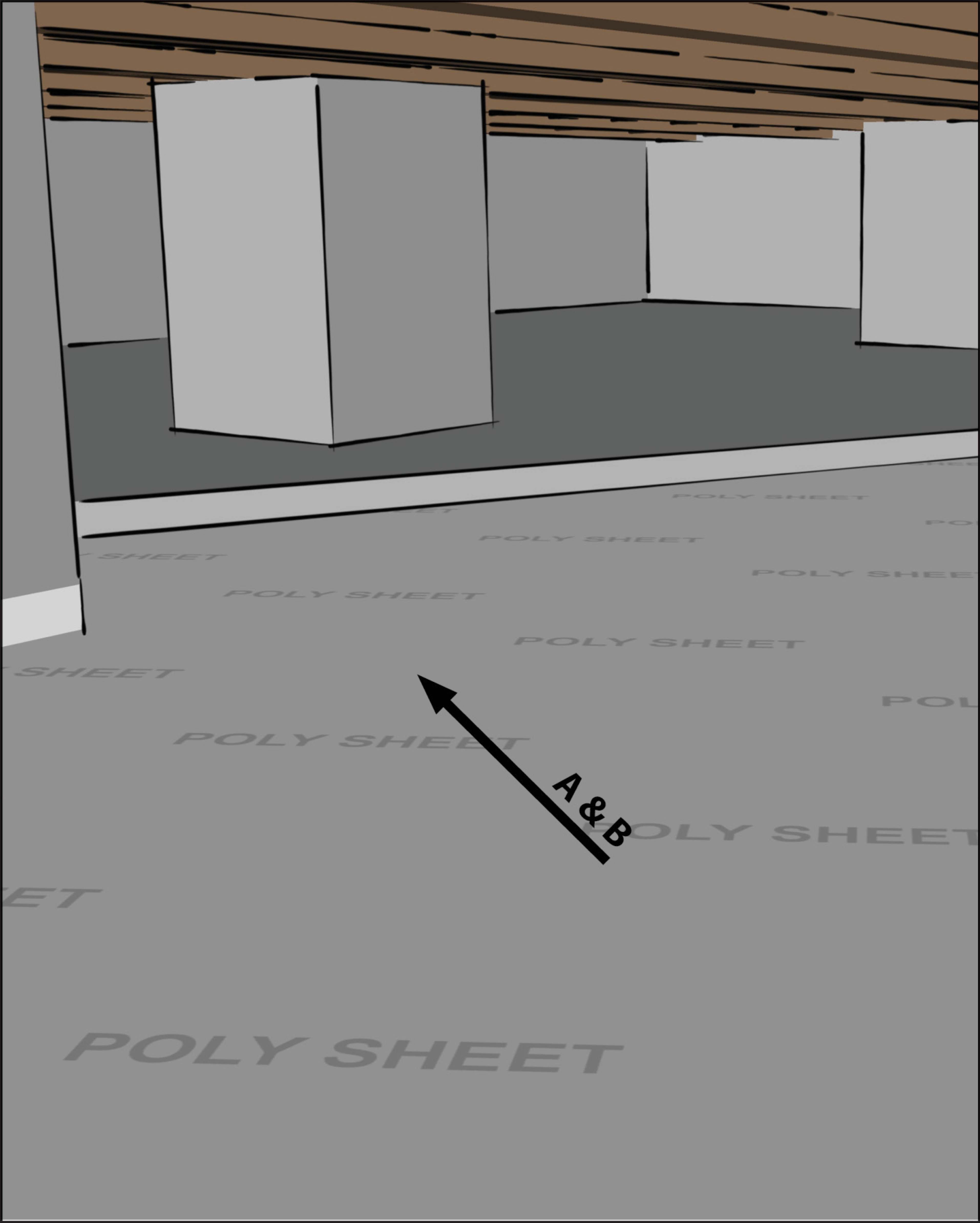
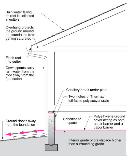
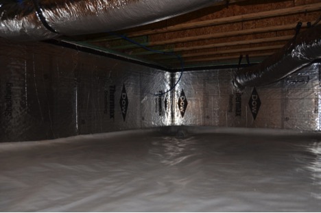
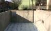
The polyethylene sheeting capillary break is shown in Figures 2 and 3, along with other good water management practices such as sloping the surface grade and impervious surfaces like driveways and patios away from the house, installing gutters and downspouts that drain away from the house, installing a capillary break between the footing wall and the sill plate, and installing drainage pipe around the footer.
The polyethylene should be sealed at all seams and around any piping to provide a complete vapor barrier as well. When a concrete slab is poured over this, it holds the sheeting in place and provides an added measure of durability, ensuring the polyethylene provides lasting protection from ground moisture. If no concrete slab is poured, the polyethylene can be secured along the perimeter of the crawlspace by fastening it to the walls or staking it. (See the guide Capillary Break at Crawlspace Floors – Polyethylene Lapped Up Walls and Piers or Secured in the Ground.)

Since a crawlspace is not living space, it does not need a full-depth 4-inch slab, as is typical for basements that may be subject to structural live loading, so crawlspace slabs are typically 2 to 4 inches thick. Installation of the polyethylene sheeting should be done by the foundation crew prior to pouring the concrete slab. Following are procedures recommended by the U.S. Environmental Protection Agency in their Indoor AirPlus Construction Specifications (EPA Indoor AirPlus). Before laying the polyethylene, after the stem walls are poured, some building scientists recommend as a best practice backfilling inside the stem wall to ensure that the crawlspace floor is above the exterior grade. This will eliminate the possibility of run-off draining directly into the crawlspace (although it won't eliminate the possibility of soils becoming saturated and wicking moisture into the crawlspace area; hence, polyethylene sheeting is still required). In locations where there is evidence that the groundwater table can rise to within six inches of the finished floor or where there is evidence that surface water doesn’t readily drain from the site, it is required by code that the crawlspace ground level be as high as or higher than the outside finished grade, unless an approved drainage system is installed (IRC 2015).
How to Install a Polyethylene Sheeting Capillary Break beneath a Concrete Crawlspace Slab
- Install a radon mitigation vent pipe if desired or required as described below.
- Install a minimum thickness of 6-mil polyethylene across the entire ground surface.
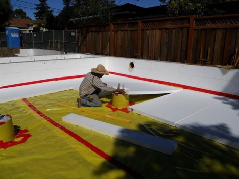
- Overlap the edges between the pieces of polyethylene by 6 to 12 inches and tape or seal all of the seams as shown in Figure 4. Seal the vapor barrier around the piers and pipes as described below.
- Pour the slab over the polyethylene, taking care not to damage the polyethylene. Do not allow the foundation crew to place a sand layer between the polyethylene and the concrete slab, as sometimes occurs. The belief is that this added layer of sand will allow the slab to dry to the bottom and help prevent the slab from curling. However, this practice is not recommended. The sand gets saturated from the concrete and wet-method curing, which only adds to the long-term moisture loading as the sand slowly dries to the crawlspace. Differential drying is better handled with a low water-to-cement ratio in the concrete mix, and covering the slab with wetted burlap or employing another effective curing method.
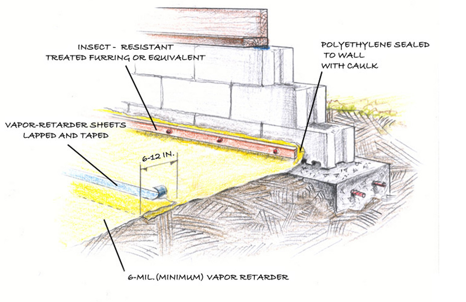
Figure 4 shows the edges of the polyethylene secured to the foundation walls with pressure-treated wood strapping, instead of covering the polyethylene with concrete. This is an acceptable alternative that is described in the guide Capillary Break at Crawlspace Floor - Polyethylene Sheeting Lapped up Walls and Piers. The important thing is to provide a lasting moisture barrier to help keep the crawlspace dry. Pouring concrete over the polyethylene, however, provides an added measure of durability that will ensure the groundcover lasts as long as the rest of the building.
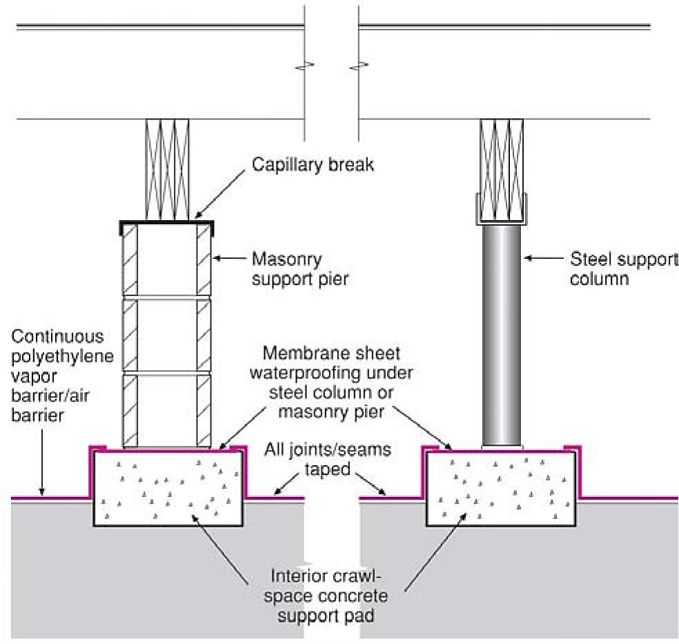
How to Install a Continuous Capillary Break at Pier Footings
In addition to securing the edges of the polyethylene to the foundation perimeter, care must be taken to provide continuous moisture control at pier footings as follows (Lstiburek 2004):
- Install a capillary break over interior footings before masonry piers or steel columns are installed (see Figure 5).
- Tape the polyethylene ground cover to the capillary break at each interior footing.
Radon Control
Check the EPA Radon zone map to verify the radon zone of your building project. In areas where the risk of radon is high, a passive radon control system should be installed under the crawlspace slab and vapor barrier to safely ventilate soil gases to the exterior of the home. This is highly recommended in Radon Zone 1, where the risk is highest. Even in Radon Zones 2 and 3, however, a radon control system will reduce the chance of soil gas concentrations building up inside the home. This is especially important in tightly built homes where the likelihood for soil gas build-up may be increased.
The following guidance is from Building America research partner Building Science Corporation (Lstiburek 2004). For additional information see the Indoor airPLUS guidance Approved radon-resistant features installed in Radon Zone 1 homes.
How to Install a Radon Control System
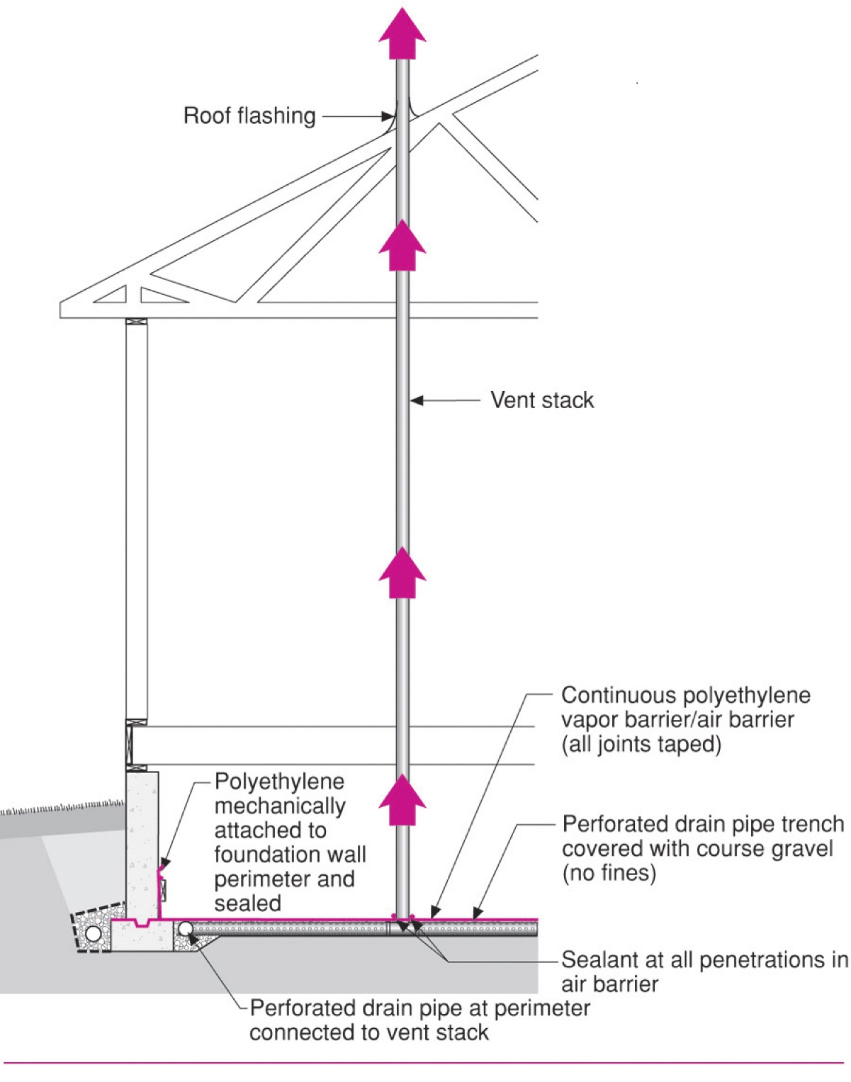
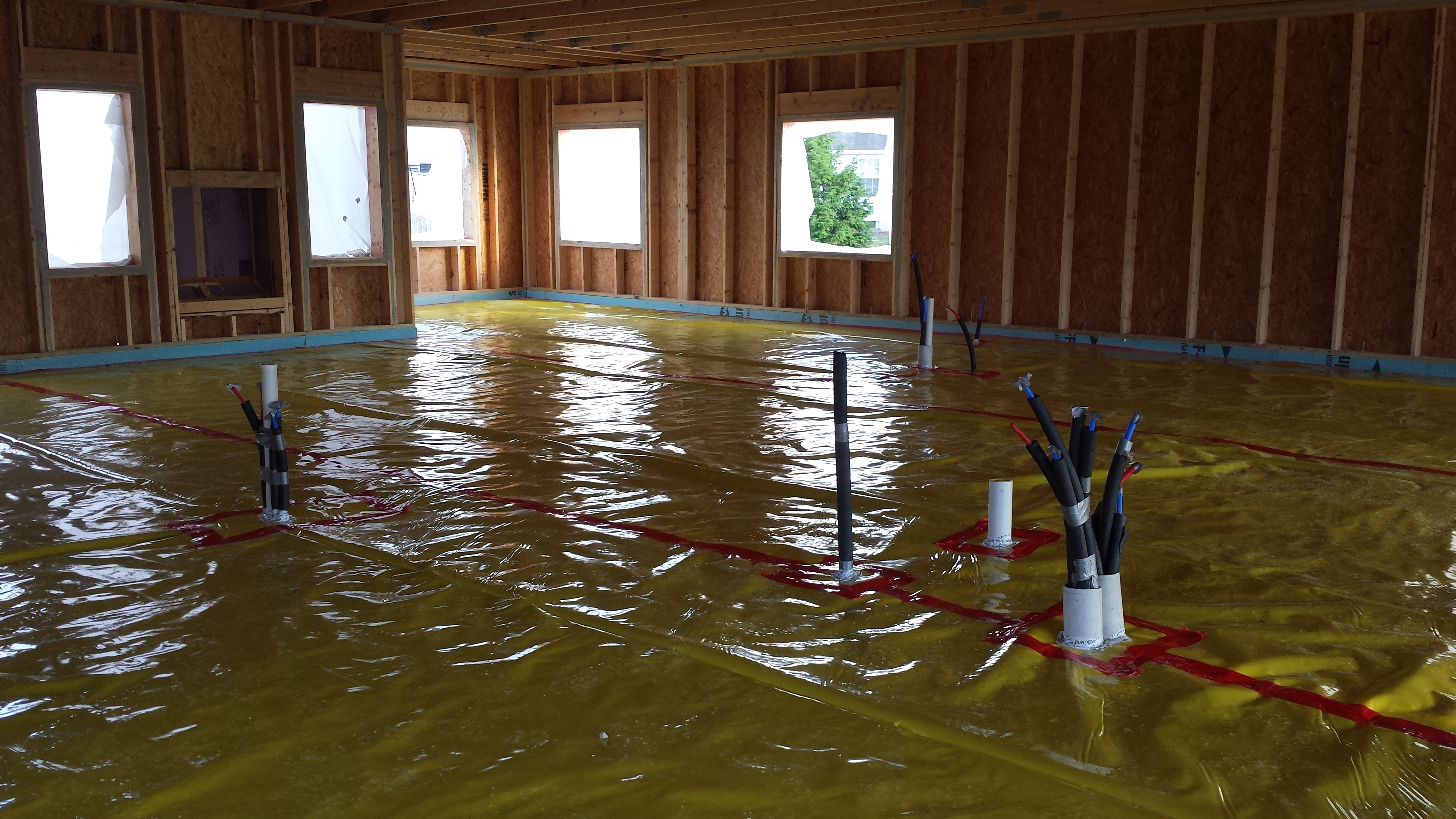
- Lay a piece of 3-inch-diameter perforated pipe that is at least 5 feet long in a gravel-filled trench running across the interior area of the crawlspace as shown in Figure 6. Bury the perforated pipe in 4 to 6 inches of course gravel (no fines); the larger the spaces between the gravel, the easier it will be for the vent stack to depressurize the area beneath the polyethylene cover
- Connect this horizontal pipe to a 3-inch-diameter vent pipe that runs vertically through the roof. The vent outlet should be located at least 1 foot above the roofline and at least 10 feet from any openings to the building such as windows, skylights, or ventilation intakes.
- Lay polyethylene sheeting over the drain pipe and gravel bed and seal all edges and around the vent stack (using a compatible caulk) as described above.
- Mechanically fasten the polyethylene to the foundation wall or pour a two-inch-thick slab over the top to improve the durability of the system.
- Monitor the radon concentration levels after the home is enclosed. If passive flow through the vent stack is insufficient to reduce radon levels below 4 pico-curies per liter, a fan rated for continuous duty can be installed on the vent stack in the attic. This will provide active depressurization of the gravel bed beneath the polyethylene and increase the rate at which the soil gas is removed.
Ensuring Success
Visually inspect the polyethylene prior to pouring the slab. Seams should overlap at least 6 inches and be taped with an acrylic- or butyl-based adhesive tape. Ordinary cloth-backed duct tape is not appropriate, as the bond will not last.
Region
The map in Figure 1 shows the climate zones for states that have adopted energy codes equivalent to the International Energy Conservation Code (IECC) 2009, 12, 15, and 18. The map in Figure 2 shows the climate zones for states that have adopted energy codes equivalent to the IECC 2021. Climate zone-specific requirements specified in the IECC are shown in the Compliance Tab of this guide.

Source
2012 edition of code establishing a baseline for energy efficiency by setting performance standards for the building envelope (defined as the boundary that separates heated/cooled air from unconditioned, outside air), mechanical systems, lighting systems and service water heating systems in homes and commercial businesses.

Source
2021 edition of code establishing a baseline for energy efficiency by setting performance standards for the building envelope (defined as the boundary that separates heated/cooled air from unconditioned, outside air), mechanical systems, lighting systems and service water heating systems in homes and commercial businesses.
Training
Right and Wrong Images
Source
Guide describing details that serve as a visual reference for each of the line items in the Water Management System Builder Checklist.
Source
Guide describing details that serve as a visual reference for each of the line items in the Water Management System Builder Checklist.
Source
Guide describing details that serve as a visual reference for each of the line items in the Water Management System Builder Checklist.

Source
Source
Videos
Compliance
More Info
Case Studies
References and Resources
*For non-dated media, such as websites, the date listed is the date accessed.
Contributors to this Guide
The following authors and organizations contributed to the content in this Guide.
Pacific Northwest National Laboratory
Building Science Corporation, lead for the Building Science Consortium (BSC), a DOE Building America Research Team.
Sales
Foundation Wall Water/Damp-Proofing = Foundation Wall Water Barrier
Technical Description
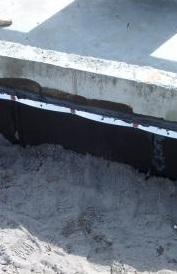
Porous concrete foundations should be treated to avoid water seepage into the home. Builders treat below-grade walls with a damp-proof coating such as an asphalt emulsion. For more reiorous protection, a plastic drainage plane may be used instead of, or in addition to, the damp proof coating. This surface coating may be joined by a layer of insulation. Rigid fiberglass allows water to drain through it; rigid polyurethane foam rated for soil contact is another option. A gravel layer is added to provide a good backfill for draining. This allows water to flow through the gravel toward the foundation footing where a perforated drain pipe will carry it away from the structure.
Questions? Comments? Contact our webmaster.