
Capillary Break Beneath Slab - Polyethylene Sheeting or Rigid Insulation

    Scope
    Scope Images
    Image
    Rigid foam insulation is taped at seams and installed over a drainage pad of aggregate to serve as a capillary break under the basement slab.
    Scope

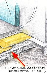
    Install a capillary break beneath slab foundations (for example, a slab-on-grade or basement slab foundation) consisting of 4 inches of aggregate stone or 4 inches of sand covered by geotextile matting. Install a vapor barrier over this consisting of 

    •  ≥ 6-mil polyethylene sheeting lapped 6-12 inches with seams sealed, or 
    • ≥ 1-inch extruded polystyrene rigid foam insulation with joints taped.

    Seal the sheeting or foam at the joints with foundation walls and around posts or pipes coming up from the ground to provide a continuous vapor barrier.

    See the Compliance Tab for related codes and standards requirements, and criteria to meet national programs such as DOE’s Zero Energy Ready Home programENERGY STAR Single-Family New Homes, and Indoor airPLUS.

    Description
    Description

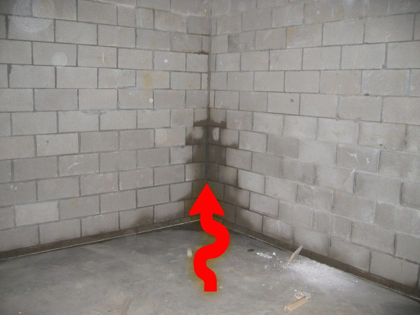
    Water gets through the foundation of most houses, either through bulk moisture leaks or through a process called capillary action. Once inside, the water can create significant problems for the home, including structural damage, mold, and poor indoor air quality.

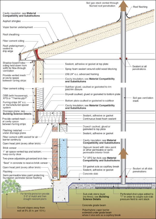
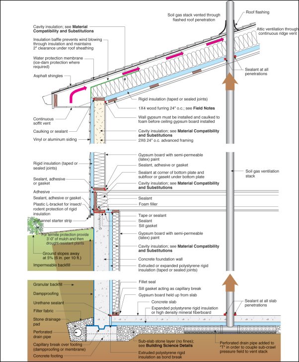
    Bulk moisture is the flow of water through holes and cracks and is addressed in the guide Exterior Surface of Below-Grade Walls. Bulk water usually moves with gravity down and through foundation walls if large openings or cracks allow it to flow freely into the building. Capillary action occurs when liquid water wicks into the tiny cracks and open spaces of porous building materials such as masonry block, concrete, or wood (see Figure 1 and Figure 2). Capillary suction enables porous materials like concrete to wick water in any direction, including upwards against gravity, for surprisingly long distances. Capillary action in concrete is theoretically capable of pulling water upward as far as 6 miles (Lsibturek, 2014). 

    Water intrusion. This image shows how water can wick through and up a foundation by way of capillary action
    Figure 1 - Capillary action pulls water up through a basement foundation wall that is not protected by a capillary break.


    This image shows how water can wick up from under the foundation and can easily seep into the crawlspace or basement
    Figure 2 - A capillary break of aggregate and polyethylene is installed under the slab but no capillary break separates the footing from the stem wall so water can wick up into the house.


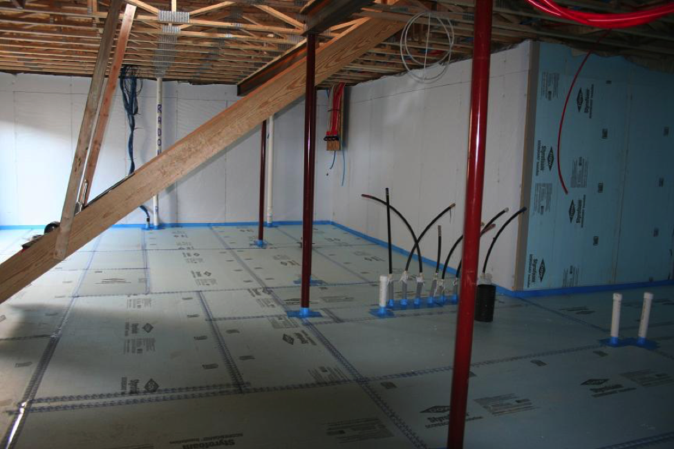
    To establish a capillary break that will prevent water from wicking up into the basement or slab-on-grade foundation, the U.S. Environmental Protection Agency’s Indoor airPLUS Construction Specifications recommend builders install a drainage pad of either aggregate or sand and geotextile matting. The large spaces between the individual stones prevent capillary action from occurring. The geotextile matting material, which consists of waffle-like or dimpled high-density plastic sheet or a matrix of plastic wire, also has numerous air gaps that prevent capillary action from occurring. Both options are shown in Figure 3. 

    Basement slab. This image show both approaches to creating a successful capillary break using aggregate and also sand with a geotextile mat
    Figure 3 - A successful capillary break under a basement slab can be created from either aggregate or sand and geotextile matting covered by a vapor barrier of polyethylene or rigid foam.


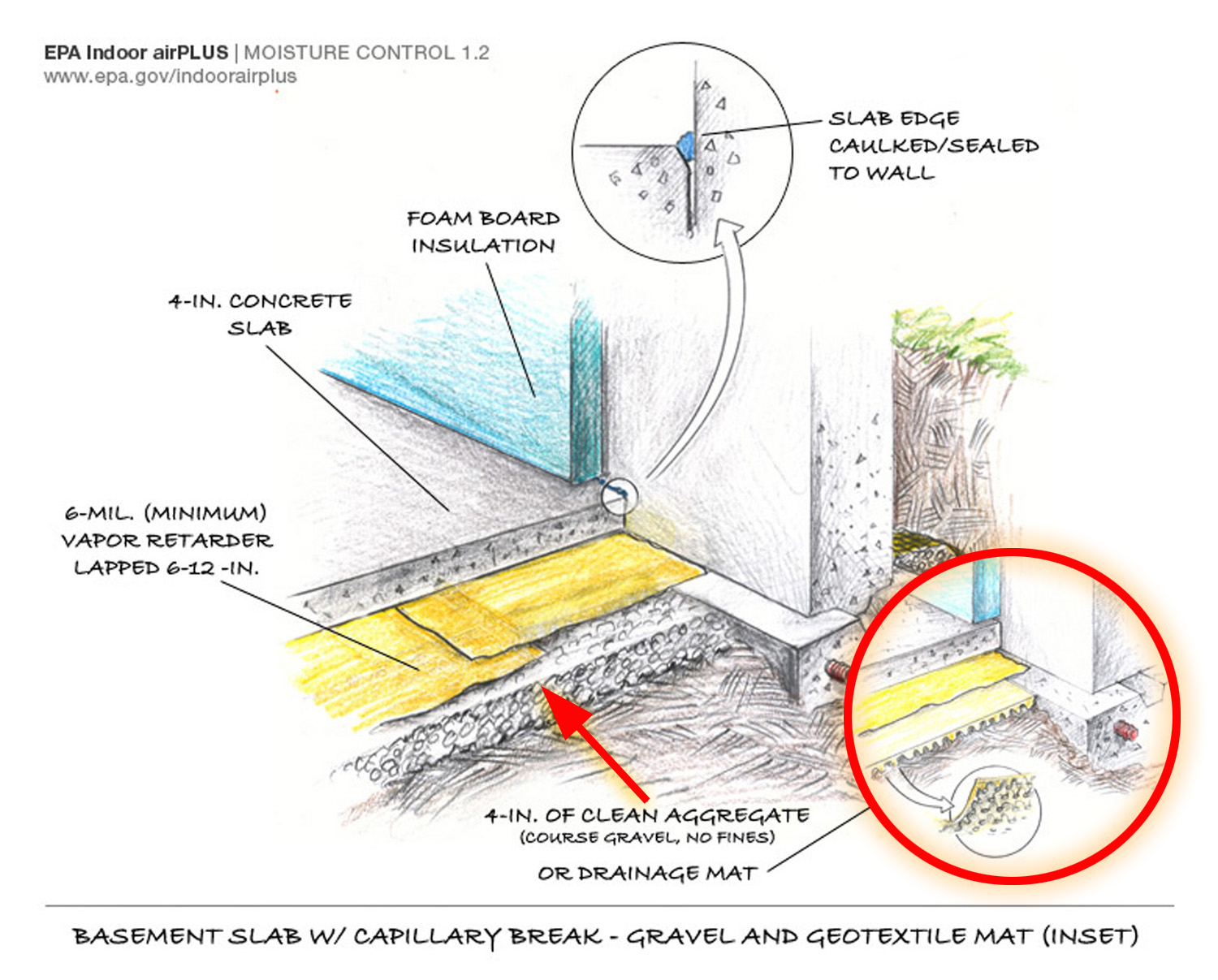
    This base is then covered with a vapor barrier of either polyethylene sheeting or extruded polystyrene rigid insulation (EPA 2018).

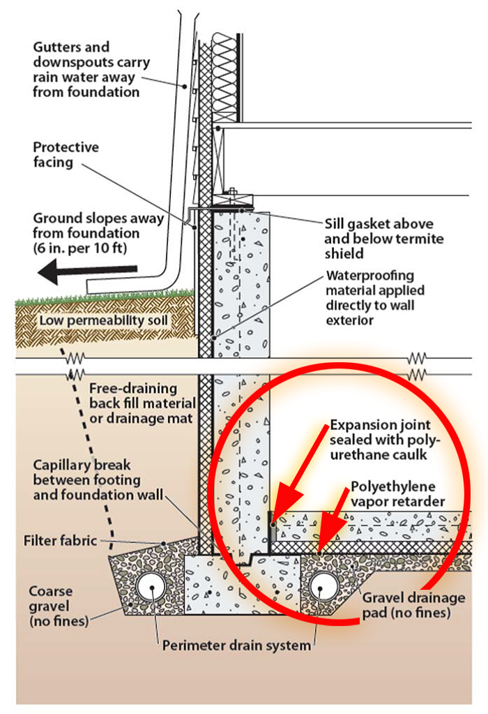
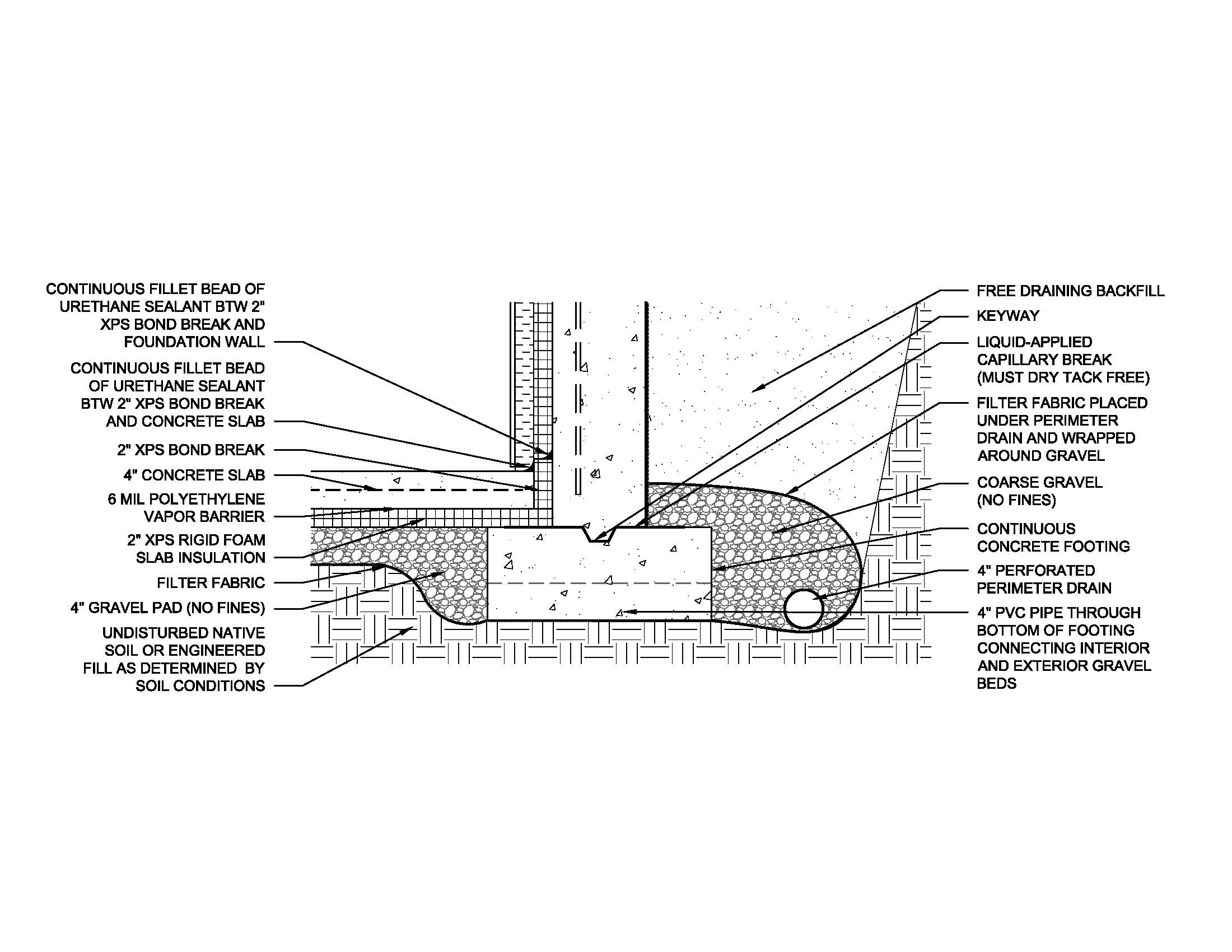
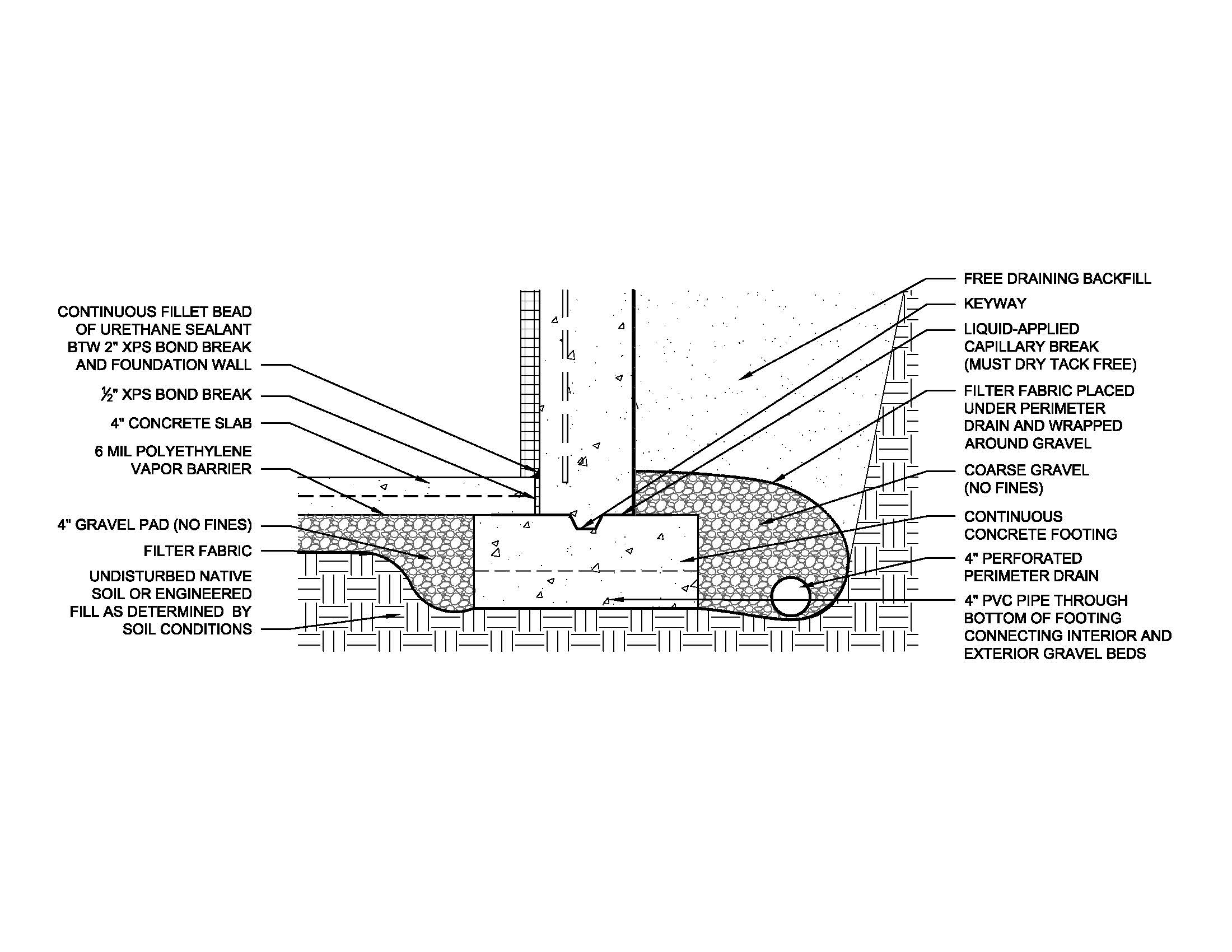
    Polyethylene sheeting is used here primarily as a vapor retarder but it also provides a capillary break. Polyethylene is sometimes used as the vapor barrier between the footing and stem wall to prevent “rising damp,” capillary action that can pull moisture up into the footing walls, as shown in Figure 2.  

    Rigid foam can also be installed, either over the polyethylene sheeting or directly on the aggregate to serve as a vapor barrier. As with the polyethylene sheeting, if the insulation serves as the vapor barrier, the joints between the insulation panels must be taped and sealed, and the concrete slab should be in direct contact with (poured directly on) the insulation or poly sheeting.

    Some builders spray closed-cell spray foam directly onto the gravel base to serve as the vapor barrier, while providing an insulation layer under the slab.

    How to Install a Capillary Break with Aggregate or Sand and Geotextile Matting

    1. Level the soil beneath the slab area.
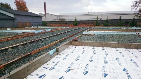
    2. Install a bed of ½-inch diameter aggregate gravel to a consistent depth of 4 inches. 
      Or, distribute a 4-inch layer of clean sand evenly across the entire pad area. Lay the geotextile matting in strips across the entire area surface, making sure it is in contact with the foundation edges. 
    3. Install radon vent pipe in gravel or sand if desired or required.
    4. Install a vapor barrier consisting of polyethylene sheeting or polystyrene rigid insulation.

    How to Install Polyethylene Sheeting as a Vapor Barrier

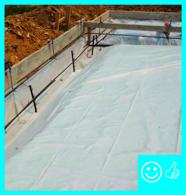
    1. Select at least 6-mil polyethylene sheeting as a minimum thickness.
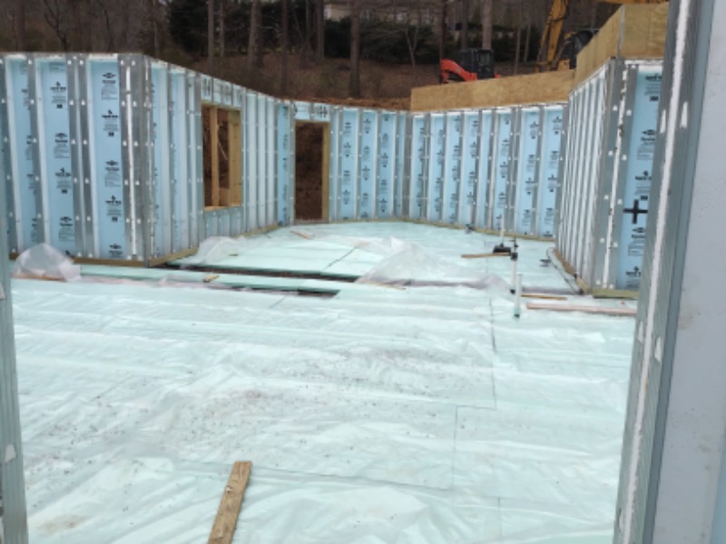
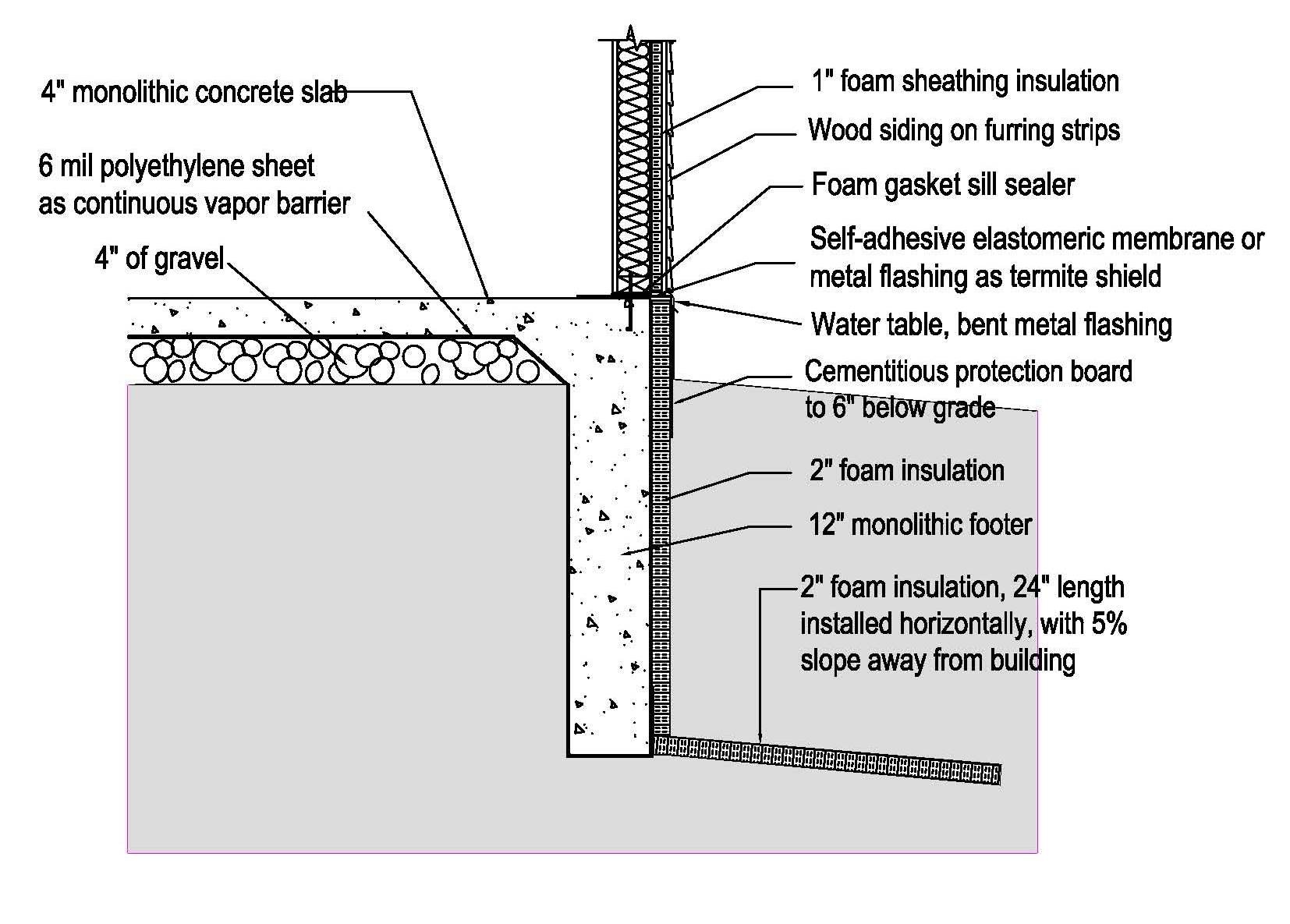
    2. Place the polyethylene sheeting over the entire foundation area making sure it touches each perimeter wall (see Figure 3 and Figure 4). The polyethylene can be extended to serve as a capillary break under the footing of a slab-on-grade foundation (as shown in Figure 5) or between the footing and the stem wall (as shown in Figure 6). 
    3. Lay the lengths of sheeting side-by-side and overlap the edges by at least 6 inches. 
      Tip: Overlap the polyethylene sheets by 12 inches to compensate for uneven cut lines.
    4. Seal the sheets together at the overlap using either a continuous bead of acoustical sealant, butyl rubber, or butyl acrylic caulk, or with tape manufactured to seal or patch polyethylene such as some builder's tapes and tapes used to repair polyethylene greenhouses (EPA 2018).
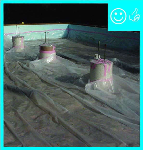
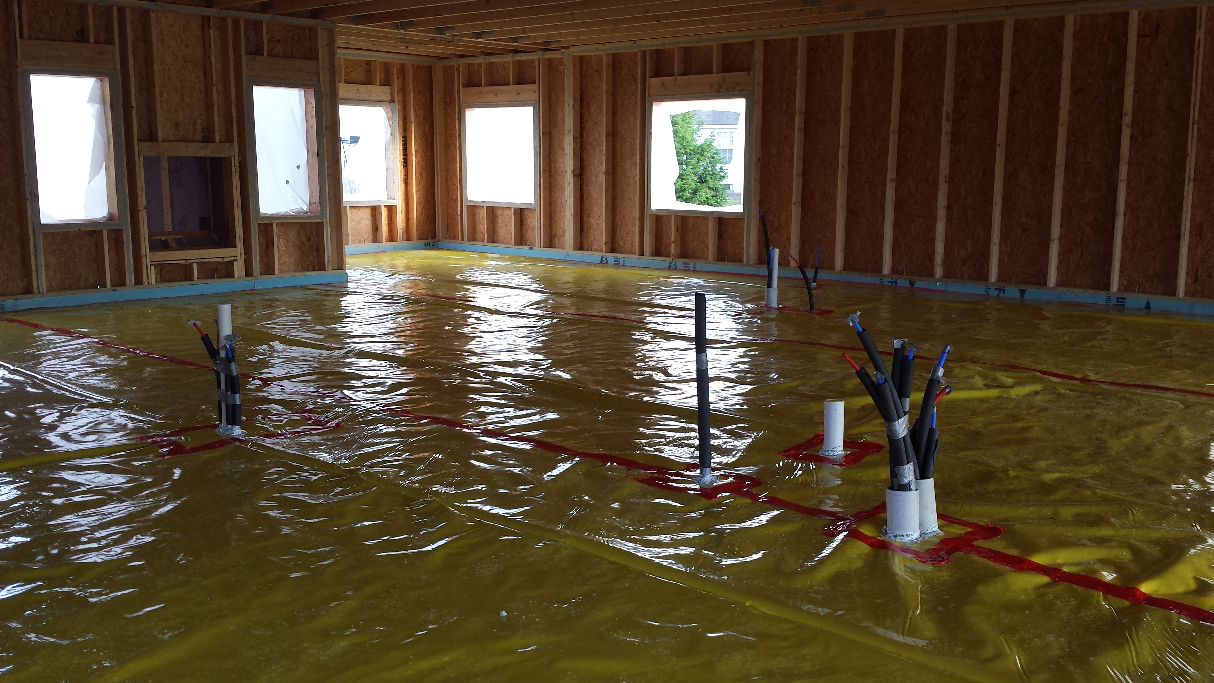
    5. Seal around any penetrations through the sheeting such as plumbing or radon mitigation piping.
    6. Pour the concrete slab directly over the polyethylene (see Figures 5, 6, and 7) or install rigid foam and then pour the concrete slab (see Figure 4). 
    Notice at every possible point of entry, either polyethylene sheets or caulk has been installed to prevent the wicking of water from under the slab
    Figure 4 - Polyethylene sheeting works with the gravel as a capillary break under the slab and serves as a capillary break between the footing and the stem wall to prevent wicking of water from underneath the slab. (Source: Upgrading Below Grade Spaces).


    House detail for hot-humid climate showing a slab-on-grade foundation with a capillary break of aggregate and polyethylene which also serves protects the footing.
    Figure 5. House detail for hot-humid climate showing a slab-on-grade foundation with a capillary break of aggregate and polyethylene which also serves protects the footing. (Source: Building Science Corporation).


    House detail showing a slab-on-grade foundation with a capillary break of aggregate and polyethylene, which also separates the footing from the foundation wall.
    Figure 6. House detail showing a slab-on-grade foundation with a capillary break of aggregate and polyethylene, which also separates the footing from the foundation wall. (Source: Steve Easley & Associates).


    Here the polyethylene sheeting can still be seen as cement is poured to create the foundation. Care must be taken when walking on the sheeting to ensure it does not tear or pull apart at the seams
    Figure 7 - Polyethylene sheeting can be seen as cement is poured to create the foundation. Care must be taken when walking on the sheeting to ensure it does not tear or pull apart at the seams. (Source: Steve Easley & Associates).


    How to Install Polystyrene Rigid Insulation as a Vapor Barrier

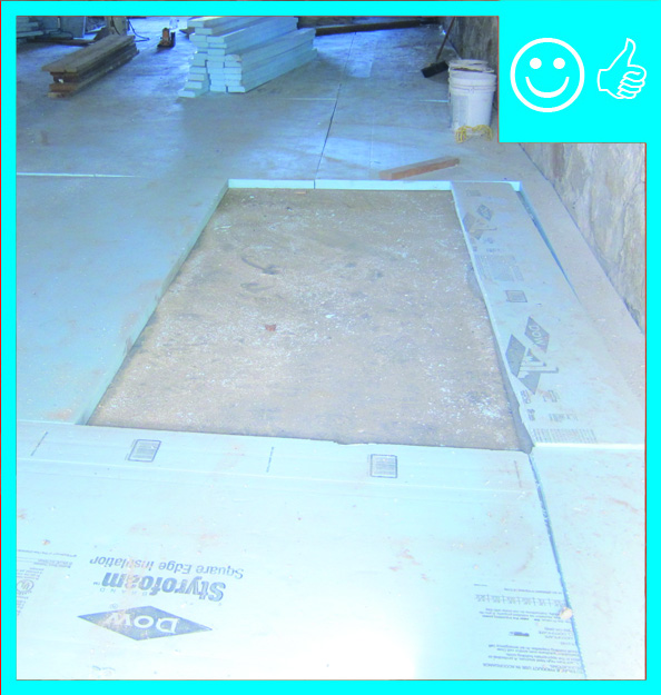
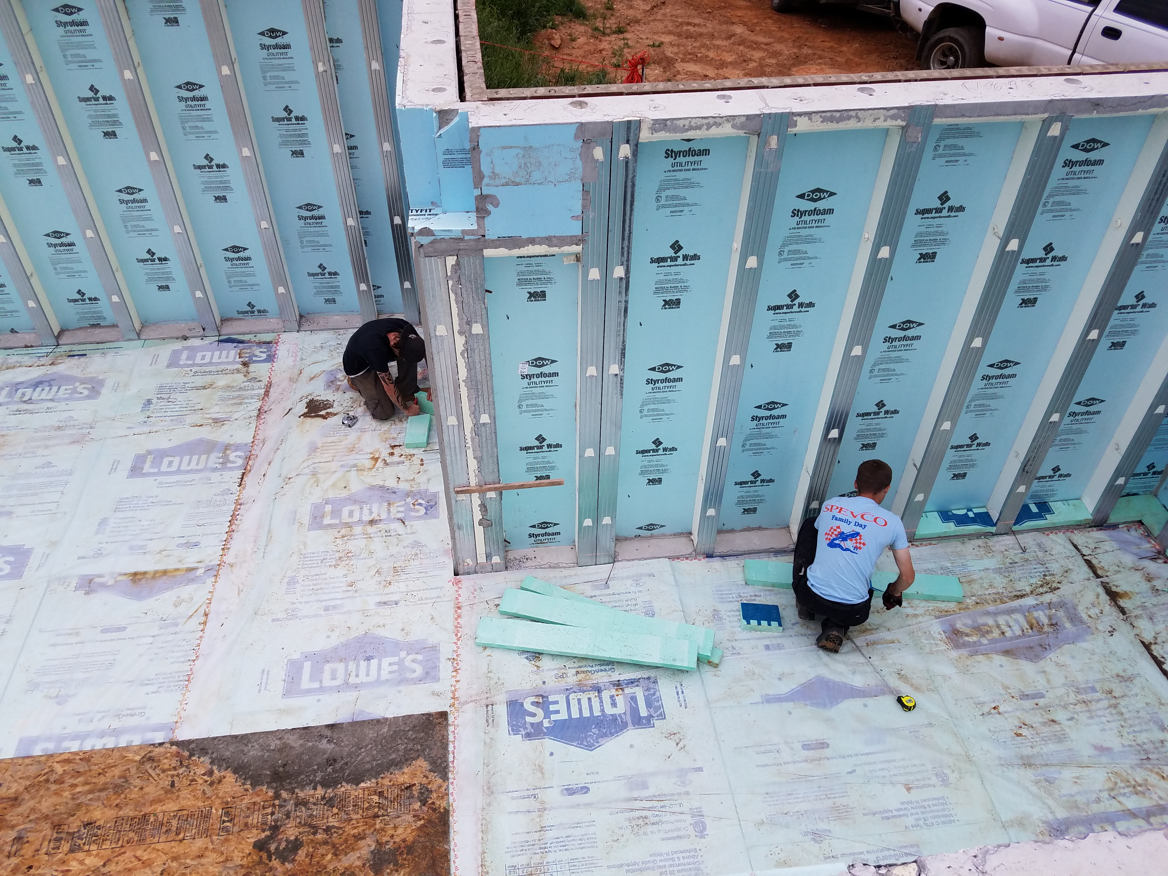
    1. Lay the polystyrene rigid insulation over the entire foundation area, making sure it touches all perimeter walls. See Figure 8.
    2. Tape and seal the joints between insulation pieces.
    3. Tape around all piping that comes through the rigid foam insulation (see Figure 9).
    4. Pour the concrete slab over the sealed polystyrene insulation.
    Rigid foam insulation is installed directly over the aggregate capillary break to serve as a vapor barrier beneath the basement slab in this house detail for the mixed humid climate.
    Figure 8. Rigid foam insulation is installed directly over the aggregate capillary break to serve as a vapor barrier beneath the basement slab in this house detail for the mixed humid climate. (Source: Building Science Corporation).


    Rigid foam insulation is installed over a drainage pad of aggregate to serve as a capillary break under the basement slab. Seams and pipes are sealed with tape and gaskets so foam can serve as a continuous vapor barrier as well.
    Figure 9. Rigid foam insulation is installed over a drainage pad of aggregate to serve as a capillary break under the basement slab. Seams and pipes are sealed with tape and gaskets so foam can serve as a continuous vapor barrier as well. (Source: IBACOS).


    Success
    Ensuring Success

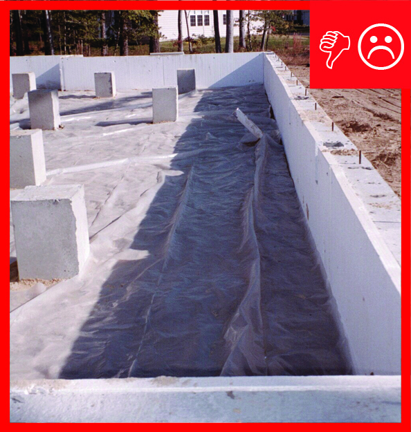
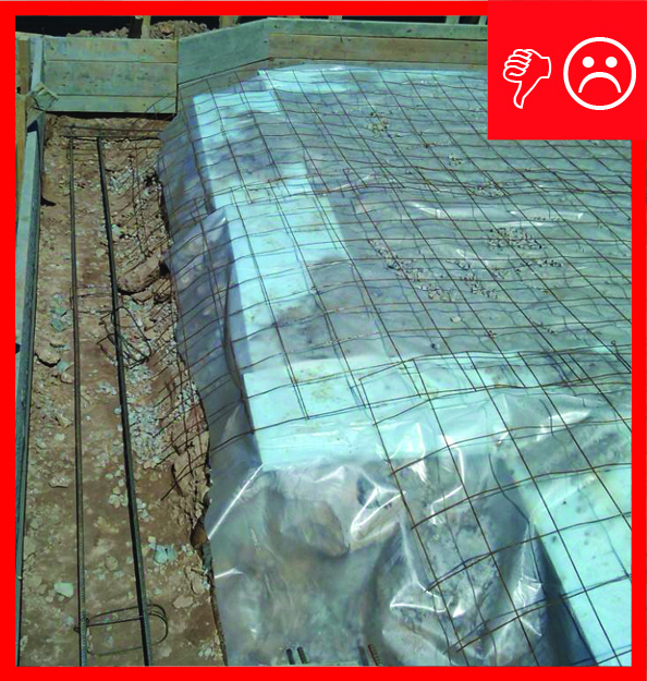
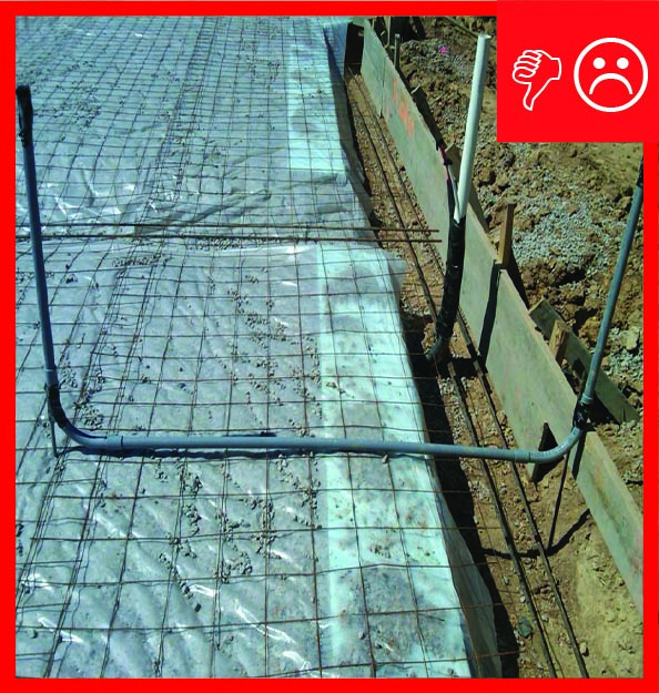
    It is critical that care be taken when installing and working around the polyethylene and/or rigid foam prior to pouring the foundation slab to maintain a complete, well-secured, and unbroken vapor barrier over the aggregate or sand and geotextile matting capillary break.  

    Climate
    Climate

    The map in Figure 1 shows the climate zones for states that have adopted energy codes equivalent to the International Energy Conservation Code (IECC) 2009, 12, 15, and 18. The map in Figure 2 shows the climate zones for states that have adopted energy codes equivalent to the IECC 2021. Climate zone-specific requirements specified in the IECC are shown in the Compliance Tab of this guide. 


    Climate Zone Map from IECC 2009, 12, 15, and 18.
    Figure 1. Climate Zone Map from IECC 2009, 12, 15, and 18. (Source: 2012 IECC)


    Climate Zone Map from IECC 2021.
    Figure 2. Climate Zone Map from IECC 2021. (Source: 2021 IECC)


    Training
    Right and Wrong Images
    Image
    Right-Polyethylene sheeting is correctly installed over aggregate and taped to pillars and foundation wall
    Right-Polyethylene sheeting is correctly installed over aggregate and taped to pillars and foundation wall
    Image
    Wrong - Polyethylene sheeting should be lapped up sides of walls and pillars and taped
    Wrong - Polyethylene sheeting should be lapped up sides of walls and pillars and taped
    Image
    Right - This rigid insulation is correctly installed in a level layer over aggregate; the seams will be taped
    Right - This rigid insulation is correctly installed in a level layer over aggregate; the seams will be taped
    Image
    Right – Polyethylene sheeting is laid over aggregate and over footing to provide a capillary break between the ground and the slab and between the footing and the stem wall
    Right – Polyethylene sheeting is laid over aggregate and over footing to provide a capillary break between the ground and the slab and between the footing and the stem wall
    Image
    Right – Polyethylene sheeting completely covers the aggregate and the footing with no tears or open seams
    Right – Polyethylene sheeting completely covers the aggregate and the footing with no tears or open seams
    Image
    Wrong – Polyethylene sheeting does not completely cover the aggregate and the footing
    Wrong – Polyethylene sheeting does not completely cover the aggregate and the footing
    Image
    Wrong – Polyethylene sheeting does not extend beyond edge of aggregate to separate the footer from the stem wall which will be poured next
    Wrong – Polyethylene sheeting does not extend beyond edge of aggregate to separate the footer from the stem wall which will be poured next
    Image
    Right – The vapor barrier is thoroughly sealed with tape at all seams.
    Right – The vapor barrier is thoroughly sealed with tape at all seams.
    Image
    Right - Workers installed rigid foam on the sill plates of these pre-cast, pre-insulated concrete wall panels, as well as on the floor, to provide a continuous layer of insulation under and around the not-yet-poured basement floor slab.
    Right - Workers installed rigid foam on the sill plates of these pre-cast, pre-insulated concrete wall panels, as well as on the floor, to provide a continuous layer of insulation under and around the not-yet-poured basement floor slab.
    Image
    Right – Two inches of rigid foam was installed on the ground before pouring the basement floor slab while precast, pre-insulated concrete panels comprise the basement walls.
    Right – Two inches of rigid foam was installed on the ground before pouring the basement floor slab while precast, pre-insulated concrete panels comprise the basement walls.
    Image
    Right - The slab-on-grade foundation is insulated with two layers (R-20) of XPS foam under the-slab and R-10 on the exterior of the stem walls.
    Right - The slab-on-grade foundation is insulated with two layers (R-20) of XPS foam under the-slab and R-10 on the exterior of the stem walls.
    Videos
    CAD
    CAD Files
    Rigid Insulation Over Aggregate
    Rigid Insulation Over Aggregate
    Download: DWG PDF
    Polyethylene Over Aggregate
    Polyethylene Over Aggregate
    Download: DWG PDF
    Polyethylene sheeting covers the aggregate and extends down and under the footing to provide a capillary break between the ground and the slab and monolithic footing
    Polyethylene sheeting covers the aggregate and extends down and under the footing to provide a capillary break between the ground and the slab and monolithic footing
    Download: DWG PDF
    Compliance

    Compliance

    The Compliance tab contains both program and code information. Code language is excerpted and summarized below. For exact code language, refer to the applicable code, which may require purchase from the publisher. While we continually update our database, links may have changed since posting. Please contact our webmaster if you find broken links.


    ENERGY STAR Single-Family New Homes, Version 3/3.1 (Rev. 11)

    National Water Management System Builder Requirements

    1. Water-Managed Site and Foundation. 
    1.3 Capillary break beneath all slabs (e.g., slab on grade, basement slab) except crawlspace slabs using either: ≥ 6 mil polyethylene sheeting, lapped 6-12 in., or ≥ 1 in. extruded polystyrene insulation with taped joints.4, 5, 6
    1.4 Capillary break at all crawlspace floors using ≥ 6 mil polyethylene sheeting, lapped 6-12 in., & installed using one of the following:4, 5, 6
    1.4.1 Placed beneath a concrete slab; OR,
    1.4.2 Lapped up each wall or pier and fastened with furring strips or equivalent; OR,
    1.4.3 Secured in the ground at the perimeter using stakes.
    1.6 Class 1 vapor retarder not installed on interior side of air permeable insulation in exterior below-grade walls.8

    Footnote 4) Not required in Dry (B) climates as shown in 2009 IECC Figure 301.1 and Table 301.1.

    Footnote 5) Not required for raised pier foundations with no walls. To earn the ENERGY STAR, EPA recommends, but does not require, that radon-resistant features be included in homes built in EPA Radon Zones 1, 2 & 3. For more information, see www.epa.gov/indoorairplus.

    Footnote 6) For an existing slab (e.g., in a home undergoing a gut rehabilitation), in lieu of a capillary break beneath the slab, a continuous and sealed Class I or Class II Vapor Retarder (per Footnote 7) is permitted to be installed on top of the entire slab. In such cases, up to 10% of the slab surface is permitted to be exempted from this requirement (e.g., for sill plates). In addition, for existing slabs in occupiable space, the Vapor Retarder shall be, or shall be protected by, a durable floor surface. If Class I Vapor Retarders are installed, they shall not be installed on the interior side of air permeable insulation or materials prone to moisture damage.

    Footnote 7) Interior surface of an existing below-grade wall (e.g., in a home undergoing a gut rehab.) listed in Item 1.5a is permitted to be finished by:

    • Installing a continuous and sealed drainage plane, capillary break, Class I Vapor Retarder (per Footnote 8) and air barrier that terminates into a foundation drainage system as specified in Item 1.8; OR
    • If a drain tile is not required as specified in Footnote 9, adhering a capillary break and Class I Vapor Retarder (per Footnote 8) directly to the wall with the edges taped/sealed to make it continuous.

    Note that no alternative compliance option is provided for existing below-grade wood-framed walls in Item 1.5b.

    Footnote 8) The 2009 IRC defines Class I vapor retarders as a material or assembly with a rating of ≤ 0.1 perm, using the desiccant method with Proc. A of ASTM E 96. The following materials are typically ≤ 0.1 perm and shall not be used on the interior side of air permeable insulation in above-grade exterior walls in warm-humid climates or below-grade exterior walls in any climate: rubber membranes, polyethylene film, glass, aluminum foil, sheet metal, and foil-faced insulating / non-insulating sheathings. These materials can be used on the interior side of walls if air permeable insulation is not present (e.g., foil-faced rigid foam board adjacent to a below-grade concrete foundation wall is permitted). Note that this list is not comprehensive and other materials with a perm rating ≤ 0.1 also shall not be used. Also, if mfr. spec.’s for a product indicate a perm rating ≥ 0.1, then it may be used, even if it is in this list. Also note that open-cell and closed-cell foam generally have ratings above this limit and may be used unless mfr. spec.’s indicate a perm rating ≤ 0.1. Several exemptions to these requirements apply:

    • Class I vapor retarders, such as ceramic tile, may be used at shower and tub walls;
    • Class I vapor retarders, such as mirrors, may be used if mounted with clips or other spacers that allow air to circulate behind them.

    Please see the ENERGY STAR Single-Family New Homes Implementation Timeline for the program version and revision currently applicable in your state.


    DOE Zero Energy Ready Home (Revision 07)

    Exhibit 1 Mandatory Requirements.
    Exhibit 1, Item 1) Certified under the ENERGY STAR Qualified Homes Program or the ENERGY STAR Multifamily New Construction Program.
    Exhibit 1, Item 6) Certified under EPA Indoor airPLUS.


    EPA Indoor airPLUS (R­evision 04)

    1.2 Capillary Break Installation. 

    • Install polyethylene sheeting or extruded polystyrene (XPS) insulation beneath concrete slabs, including basement floors. Ensure sheeting is in direct contact with the concrete slab above (ENERGY STAR requirement).
    • Install a capillary break at all crawlspace floors using ≥ 6 mil polyethylene sheeting, lapped 6 to 12 in. (ENERGY STAR requirement).
    • Under the polyethylene sheeting or extruded polystyrene (XPS), insulation installed to meet ENERGY STAR Water Management System Builder Checklist Item 1.3: 
      • Install a 4 in. layer of 1/2 in. diameter or greater clean aggregate; OR
      • Install a 4 in. uniform layer of sand, overlain with either a layer of geotextile drainage matting throughout or strips of geotextile drainage matting along the perimeter installed according to the manufacturer’s instructions.

    Exceptions to the aggregate or sand requirement (Not applicable in EPA Radon Zone 1):

    • Dry climates, as defined by 2015 IECC Figure 301.1.
    • Areas with free-draining soils – identified as Group 1 (Table R405.1, 2015 IRC) by a certified hydrologist, soil scientist, or engineer through a site visit.
    • Slab-on-grade foundations.

    Alternative path for gut-rehabs: For an existing slab in a home undergoing a gut rehabilitation in Radon Zones 2 and 3, the alternate slab treatment in the ENERGY STAR Water Management System Builder Checklist, footnote 5, shall apply as an alternative to polyethylene and aggregate or sand under the slab. Homes undergoing gut rehabilitation in Radon Zone 1 must also install an active radon system utilizing sub-slab depressurization, and radon levels shall be verified upon final inspection to be below the EPA action level (4pCi/l) to receive qualification.

    Note: In EPA Radon Zone 1 (see Specification 2.1):

    • Polyethylene sheeting must be installed and overlapped by 6 to 12 in. at the seams.
    • ENERGY STAR staking method for poly sheeting may not be used in crawlspaces with no slab.
    • ENERGY STAR exceptions for capillary break (polyethylene) under slabs do not apply. Poly is required in Radon Zone 1.

    Advisory: 10 mil polyethylene is recommended if crawlspace floors are not covered with a concrete slab.

    2.1 Radon-Resistant Construction. Construct homes in EPA Radon Zone 1 with radon-resistant features (a passive system at minimum). EPA recommends that radon-resistant features are installed according to ANSI/AARST CCAH for 1-2 family dwellings and townhouses (max. total foundation area of 2500 sq. ft.) OR ANSI/AARST CC-1000 for larger foundations. 

    Visually verify the following requirements:

    • Capillary break installed according to Specification 1.2, irrespective of climate zone.
    • A 3 or 4 in. diameter gas-tight vertical vent pipe, clearly labeled as a component of a radon reduction system. The vent pipe shall be connected to an open T-fitting in the aggregate layer (or connected to geotextile drainage matting according to the manufacturer’s instructions) beneath the polyethylene sheeting, extending up through the conditioned spaces and terminating a minimum of 12 in. above the roof opening. At least 10 ft. of horizontal perforated drain tile is to be attached to the T-fitting beneath the polyethylene sheeting placed over earthen crawlspaces and below concrete slabs. Note: suction points are not permitted on sump lids.
    • Radon fan (i.e., an active system) OR an electrical receptacle installed in an accessible attic location near the radon vent pipe (i.e., a passive system) to facilitate future fan installation if needed. A space surrounding the radon pipe, having a vertical height of not less than 48 inches and a diameter of not less than 21 inches, shall be provided in the attic area where the radon fan can be installed, if required.
    • Homes with no accessible attic location for a fan must utilize another exterior location or a garage that is not below conditioned space per ANSI/AARST CCAH. The branch circuit supply shall be labeled at the electrical panel indicating its intended use.
    • Foundation air sealing with polyurethane caulk or the equivalent at all slab openings, penetrations and control or expansion joints.

    Note: Larger buildings and multifamily properties may share mitigation systems across multiple units or may require multiple soil gas vent systems to accommodate large building footprints. See ANSI/AARST CC-1000 for electric metering requirements in shared (collateral) mitigation systems, as well as for maximum nominal sizes of soil gas collection plenums and corresponding pipe sizes.

    Note: Consult local building codes to determine whether additional radon requirements apply. Also consult EPA's "Building Radon Out" (EPA 402-K-01-002) for general guidance on installing radon-resistant features.

    Advisories:

    1. Elevated levels of radon have been found in homes built in all three zones on EPA’s Map of Radon Zones. Consult your state radon program for current information about radon in your area. Go to EPA's radon website and click on your state for contact information.
    2. EPA recommends, but does not require, that all homes built with radon-resistant features in EPA Radon Zone 1 include a radon vent fan. EPA also recommends radon-resistant features for homes built in EPA Radon Zones 2 and 3, and that all homes with or without radon-resistant features be tested for radon prior to occupancy. A radon vent fan should be installed when the test result is 4 pCi/L (the EPA action level) or more.
    3. Provide buyers with EPA’s Citizen’s Guide to Radon, encourage them to test for radon and refer them to EPA's radon website for more information.
    4. If soil or groundwater contamination is suspected on or near the building site (e.g., former industrial sites), volatile chemical contaminants from soil gas or vapor intrusion into a building may pose an IAQ risk. In such cases, EPA recommends radon-resistant features consistent with Specification 2.1, which can minimize or prevent the vapor intrusion into a house. See the EPA Vapor Intrusion Primer or ASTM E2600 for more information. You should also consult your state, tribal, or local environmental regulatory agency for information on the location of contaminated sites, including those subject to Superfund (CERCLA), Resource Conservation and Recovery Act (RCRA) cleanup requirements, or the Brownfields program. Visit EPA’s “Where You Live” for more information.

    See Indoor airPLUS Specifications for exceptions and for an alternative path for gut rehabs. 


    2009, 2012, 2015, and 2018 International Residential Code (IRC)

    Section R506.2.3 Vapor retarder. A 6-mil polyethylene (or other approved) vapor retarder to have joints lapped not less than 6 inches must be placed between the concrete slab and the base course or prepare subgrade if no base course exists. Exceptions: Detached garages, utility buildings, other unheated accessory structures, unheated storage rooms less than 70 square feet, carports, driveways, walks, patios, and other flatwork not likely to be later enclosed or heated, and where approved by the building official.

    2021 IRC

    Section R506.2.3 Vapor Retarder. A minimum 10-mil (0.010 inch; 0.254 mm) vapor retarder conforming to ASTM E1745 Class A requirements with joints lapped not less than 6 inches (152mm) shall be placed between the concrete floor slab and the base course or the prepared subgrade where a base course does not exist. Exceptions: Detached garages, utility buildings, other unheated accessory structures, unheated storage rooms less than 70 square feet, carports, driveways, walks, patios, and other flatwork not likely to be later enclosed or heated, and where approved by the building official.

    Retrofit:  2009, 2012, 2015, 2018,  and 2021 IRC

    Section R102.7.1 Additions, alterations, or repairs. Additions, alterations, renovations, or repairs shall conform to the provisions of this code, without requiring the unaltered portions of the existing building to comply with the requirements of this code, unless otherwise stated. (See code for additional requirements and exceptions.)

    Appendix J regulates the repair, renovation, alteration, and reconstruction of existing buildings and is intended to encourage their continued safe use.

    More

    More Info.

    Access to some references may require purchase from the publisher. While we continually update our database, links may have changed since posting. Please contact our webmaster if you find broken links.

    Case Studies
    References and Resources*
    Author(s)
    U.S. Environmental Protection Agency
    Organization(s)
    EPA
    Publication Date
    Description
    Guide describing details that serve as a visual reference for each of the line items in the Water Management System Builder Checklist.
    Author(s)
    U.S. Department of Energy
    Organization(s)
    DOE
    Publication Date
    Description
    Website describing the U.S. Department of Energy's residential buildings program.
    Author(s)
    Huelman Patrick H,
    Breidenbach Sam,
    Schirber Steve
    Organization(s)
    NorthernSTAR,
    University of Minnesota,
    NSTAR
    Publication Date
    Description
    Presentation describing the challenges of insulating an existing basement, presented to the Building America residential energy-efficiency stakeholder meeting.
    Author(s)
    Lstiburek
    Organization(s)
    Building Science Corporation,
    BSC
    Publication Date
    Description
    Article describing correct ways to eliminate water damage by incorporating a sacrificial layer to foundation walls and footings.
    *For non-dated media, such as websites, the date listed is the date accessed.
    Contributors to this Guide

    The following authors and organizations contributed to the content in this Guide.

    Sales
    Building Science Measures
    Building Science-to-Sales Translator

    Foundation Capillary Break over Aggregate = Foundation Floor Water Barrier

    Image(s)
    Technical Description

    Without an effective moisture barrier, water can penetrate the pores of a concrete foundation slab, which can potentially lead to moisture-related issues. To prevent moisture from wicking up into the concrete slab and foundation walls, a water-proof layer is installed under the concrete consisting of 6-mil plastic sheeting overlapped and taped at the seams or soil-contact-rated rigid foam taped at all seams. Under this barrier is a 4-inch layer of gravel to help moisture drain away. In crawlspaces, plastic sheeting should installed over the dirt floor.

    Foundation Floor Water Barrier
    Sales Message

    Foundation floor water barriers help drain water away from under the slab. What this means to you is peace-of-mind knowing your home has a comprehensive set of measures that minimize the risk of water damage in your basement. Wouldn’t you agree every home should have full water protection?

    Last Updated

    Mobile Field Kit

    The Building America Field Kit allows you to save items to your profile for review or use on-site.

    Sign Up  or  Log In

    Did you find this information helpful?

    If you have questions and/or would like a reply to this feedback, please include your e-mail address in the message.
    This question is for testing whether or not you are a human visitor and to prevent automated spam submissions.