Scope
Reroof an existing home and add exterior rigid insulation above the roof deck before installing the new cladding to improve the durability and moisture control of the roof as well as to improve thermal performance and provide a conditioned attic. The best time to implement this approach from a cost perspective is when an existing roof is being replaced. This retrofit assembly is appropriate for homes with unvented, conditioned attics or where the retrofit is intended to create an unvented, conditioned attic.
- Remove the existing roofing and non-adhered underlayment to expose the roof sheathing.
- Apply a continuous air control membrane to the existing roof sheathing or implement continuous air control at the roof sheathing. Ensure air sealing around any roof penetrations.
- Install rigid insulation board in multiple layers with joints offset vertically and horizontally between adjacent layers. Rigid insulation layers exterior to the existing roof sheathing must provide sufficient thermal insulation (R-value) to control condensation risk (see climate-specific guidance).
- Install a nail base for the cladding. The nail base must be vented in high snow-load areas.
- Install roofing underlayment, flashing, and cladding as per best practices. See the guide Step and Kick-Out Flashing at Roof-Wall Intersections and the guide Heavy Membranes at Eaves in Cold Climates.
- Install cavity insulation (e.g., netted fibrous insulation, batt, or open-cell spray foam insulation) to achieve the desired total assembly R-value. See the guide Insulation Installation (RESNET Grade 1)
- Address combustion safety and controlled mechanical ventilation as needed, given the increased airtightness associated with this retrofit.
For more on roof/wall connections, see the U.S. Department of Energy’s Standard Work Specifications.
See the Compliance Tab for links to related codes and standards and voluntary federal energy-efficiency program requirements.
Description
Sloping roofs should be designed to drain water away from the top of buildings; the steeper the slope, the better the drainage. The materials that form the water control layer overlap each other in shingle fashion or are sealed so that water drains down and out and does not collect on the roof. It is vital that any roof penetrations (drains, skylights, or mechanical curbs) are properly flashed to prevent water entry.
A retrofit that involves re-roofing provides the opportunity to install rigid foam insulation above the roof deck and to integrate the foam with continuous water, air, and vapor control layers that are also installed on the roof deck. This approach can achieve a high R-value roof enclosure that offers robust water control while providing a conditioned, unvented attic space for storage and for housing the home’s HVAC system and/or ducts.
If the home has cathedral ceilings, where existing interior finishes are installed against the roof framing, this exterior insulation approach permits higher attic R-values to be achieved with less likely disturbance of interior finishes.
If the retrofit project includes, or will include in the future, the addition of rigid foam on the exterior of the walls, an extension of the overhangs at the eaves and/or rakes may be needed because retrofit walls may be thicker than the existing standard construction. If this extension lowers the elevation of the soffit at the eaves, it may conflict with the existing window head heights or head trim. This needs to be taken into account during planning for the overall retrofit. Typically, this situation can be avoided if the roof is raised several inches, as is the case with the retrofit solution described here.
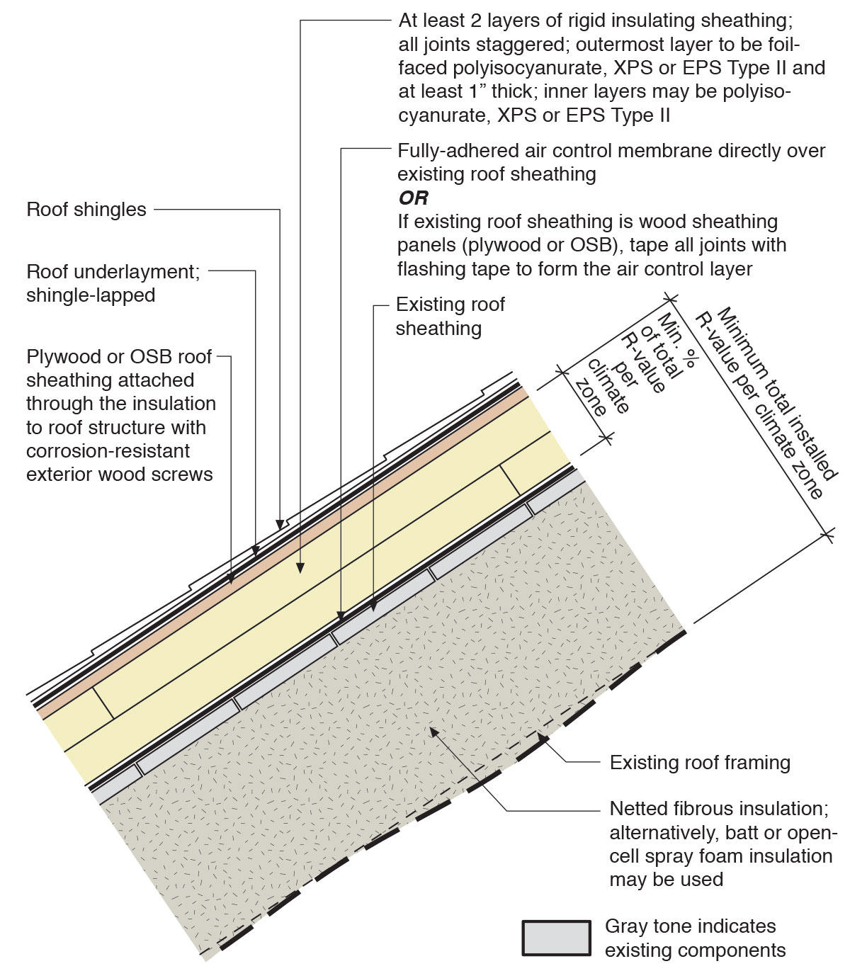
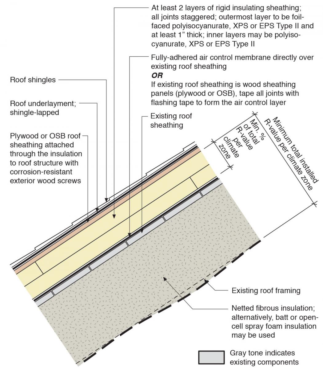
Figure 1 shows a retrofit of an existing roof where two layers of rigid foam, with seams staggered, are installed along with new moisture and air control layers over the existing sheathing. New sheathing and new cladding are installed over the exterior rigid foam as part of this roofing retrofit. Additional insulation is installed in the cavities between the roof rafters to create an unvented attic. Options for the cavity insulation include open-cell spray foam or batt insulation, or netting can be stapled to the underside of the rafters and the cavities can be filled with blown cellulose or fiberglass. This retrofit assembly is for an unvented attic space. If there are soffit vents or other vents in the existing attic, they should be sealed off prior to installing the insulation.
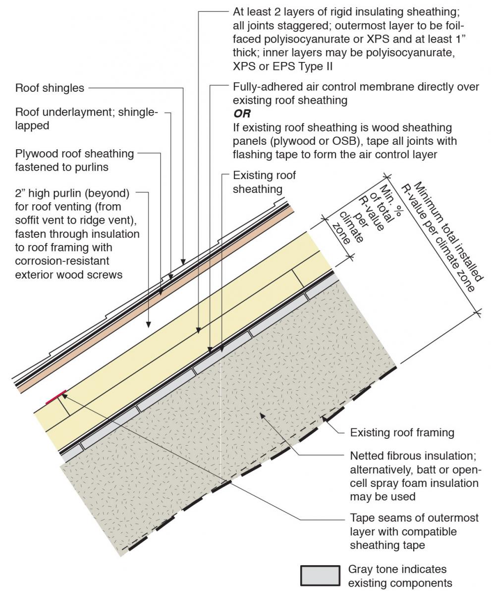
Figure 2 shows an assembly with insulation, air and water sealing layers that are similar to those shown in Figure 1; however, there is one important difference. Purlins or furring strips have been installed above the rigid foam to provide an air gap for venting between the rigid foam and the new sheathing and roof cladding. This ventilation gap is especially needed in cold climates with high snow loads. The venting helps to keep the surface of the roof cooler, which helps to minimize the likelihood of snow melting then refreezing at the roof eaves, which can lead to the formation of ice dams. With this assembly, the attic itself is unvented; however, the roof can be vented via soffit and ridge vents that are open to the venting layer in the roof assembly but separated from the attic.
In the drawings, the roof cladding is represented as shingles, but other roof claddings, such as standing seam metal roofing, would be acceptable provided that the attachment of the roof cladding does not result in horizontal obstructions in the water control layer beneath the cladding.
All other things being equal, providing insulation to the exterior of the roof framing tends to lower the equilibrium moisture content of wood roof framing. The approach can result in roof framing and sheathing that is dryer and also has an enhanced ability to dry. Bringing an attic into conditioned space allows ductwork, mechanical equipment, plumbing, and fire protection systems to be located in the attic space and has the added benefit of providing attic storage that is protected from temperature extremes.
The existing roof cladding and any non-adhered underlayment must be removed to allow an air control membrane to be installed on the roof deck or established at the roof deck. Robust air control is essential for a high-performance enclosure. An air control membrane is needed below the insulating sheathing to prevent moisture-laden air from migrating through the joints in the insulating sheathing. With the right materials and detailing, the air control membrane can also provide temporary water protection and permanent back-up water protection.
There are three options for establishing an air control layer on top of the original roof sheathing. These are listed relative to air control and temporary/back-up water control performance:
Good – The original non-adhered roof underlayment is made air tight by taping the seams and applying sealant or tape to make air-tight connections to the air control layers of adjacent assemblies. Make sure all seams are properly lapped. If the existing roof sheathing consists of sheets of plywood or OSB rather than individual boards, the air control layer can be established by taping the joints between these sheathing panels.
Better – The original sheathing product has a self-adhered air and water control membrane that is an integral part of the sheathing product. Because insulation will be installed to the exterior of the sheathing layer, the product may not need to be specifically designated for roof applications; however, traction on steep slopes must be a priority consideration for workers’ safety. Make sure all seams are properly lapped.
Best – A fully adhered, self-sealing ice and water control membrane is installed over the original sheathing with any seams overlapped shingle style. There are rare situations that would require the air control membrane to be vapor permeable. However, in most situations, it is not a benefit to have a vapor-permeable air control layer in this assembly. The list of Good, Better, Best reflects the more general case.
In cold climates, the insulating sheathing installed above the roof deck should comprise at least 40% of the total roof assembly R-value for most cold-climate applications. See BSD-163: Controlling Cold Weather Condensation Using Insulation (Straube 2011). Too little insulation above the roof deck increases the risk of condensation at the roof sheathing.
The insulation installed over the roof deck must be installed in multiple layers with joints offset in order to control convective looping at joints between insulation panels.
Materials appropriate for insulating sheathing with an unvented cladding substrate include:
- polyisocyanurate
- extruded polystyrene (XPS)
- expanded polystyrene (EPS) type II
- semi-rigid mineral fiber insulation boards, provided the material has adequate compressive strength. Mineral fiber with compressive strength of 0.625 psi at 10% deformation has been shown to work in wall systems where furring strips are installed over the insulation.
In a configuration with a vented cladding substrate (such as is used for ice dam protection in high-snow-load areas), the outer layer of insulating sheathing must be detailed as a drainage plane. Therefore, among other characteristics, it must have surfaces that provide a suitable substrate for flashing or sheathing tapes. Insulation materials appropriate for the outer layer of insulating sheathing include:
- XPS
- foil-faced polyisocyanurate.
An unvented roof cladding substrate (e.g., plywood or OSB roof sheathing) can be installed over exterior insulation layers using long, exterior-grade screws. The screws must be long enough to penetrate an adequate depth into the roof framing. Marking the location of framing on successive layers is very important for locating the framing, particularly when the framing has irregular spacing.
If purlins are used to create a vented over-roof, the purlins are fastened to the framing through the insulating sheathing. The substrate for the roof cladding is then fastened to the purlins much as it would be fastened to a new roof. Gaps should be located along the length of the purlins to provide cross ventilation to effectively vent roofs with hips, valleys, or other obstructions to the soffit-to-ridge ventilation space. Large gaps in the purlins must be coordinated with the nailing pattern for the cladding substrate.
Once the substrate for the roof cladding is installed, installation of roofing underlayment, flashing, and cladding follows best practices. See the guide Step and Kick-Out Flashing at Roof-Wall Intersections and the guide Heavy Membranes at Eaves in Cold Climates.
Installation of cavity insulation follows typical best practices. See Insulation Installation (RESNET Grade 1). Note that too much insulation installed to the interior can upset the condensation control of the assembly. In cold climates, the insulating sheathing installed above the roof deck should comprise at least 40% of the total attic assembly R-value for most cold-climate applications as noted above and in Straube 2011. See the Climate tab for more information.
If installing closed-cell spray foam or other low-permeance insulation to the interior, it is very important to verify that the roof sheathing and framing are dry (e.g., 12%-15% moisture content or less) before installing cavity insulation. It is also a good idea to verify that the sheathing and wood framing are dry before installing any kind of cavity insulation.
It is generally best to install cavity insulation only after the new exterior water management system is installed. However, in certain circumstances, it may be desirable and necessary to install cavity insulation from the exterior. The risk that must be managed is water penetration to the roof sheathing or cavity insulation after installation of the cavity insulation. Although a properly designed assembly will be able to control the condensation risk of diffusion or air-transported moisture, the insulation to the interior of the roof sheathing will inhibit the ability of the assembly to dry if a bulk water leak occurs. The system is more vulnerable to moisture between the time that the existing roofing is removed and new water control systems are installed. If water leaks into the assembly after the insulation is installed, the insulation must be removed, the source of the leak identified and corrected, and the sheathing and framing allowed to dry thoroughly (to less than 15% moisture content) before cavity insulation is replaced.
Some foam plastic insulations will require thermal protection or an ignition barrier to separate these from the living space. Consult the manufacturer of the insulation material and the local building code to learn about specific requirements.
How to Insulate a Sloped Roof with Exterior and Interior Insulation
- Remove the existing roofing and non-adhered roof underlayment and inspect the structural integrity of the roof. Check the roof framing for any deficiencies, rot, insect damage, etc. Proceed only after repairs are completed. Based on the findings, revise the roof assembly and review specific detailing as needed. Follow the minimum requirements of the current adopted building and energy codes.
- a. Apply a continuous air control membrane to existing roof sheathing. ALTERNATELY b. Tape all joints between roof sheathing panels with an acrylic or butyl adhesive flashing tape/membrane.
- Mark the location of framing on the air control membrane to facilitate attachment of roofing substrate or purlins.
- Seal around any penetrations through the air control layer. If the air control layer is to provide water control, provide proper flashing as well as air sealing for penetrations.
- Install rigid insulation board over the air control layer in multiple layers with joints offset vertically and horizontally between adjacent layers. IF PROVIDING A VENTED OVER-ROOF:
- Detail the outer layer of the insulating sheathing as a drainage plane.
- Transfer the markings for framing locations through each layer of insulating sheathing.
- a. Install substrate for cladding. ALTERNATELY b. Install purlins and cladding substrate.
- Install roof underlayment, flashing, and cladding as per best practices. See the guide Step and Kick-Out Flashing at Roof-Wall Intersections and the guide Heavy Membranes at Eaves in Cold Climates.
- Install cavity insulation (netted fibrous insulation, batt insulation, or spray foam insulation) to achieve the desired total assembly R-value. See the guide Insulation Installation (RESNET Grade 1).
Success
Ensure that the roof system provides robust protection from rain water and ice dams and that proper flashing is in place. Also ensure that the roof structure is adequate to support any additional load that may be added.
Refer to the current adopted building and energy codes for information on appropriate levels of insulation for the different climate zones as well as for the proper ratios of vapor and air-impermeable and permeable insulation.
Remediate any hazardous conditions that will be affected (e.g., exposed or aggravated) by the planned work. Examples of hazardous materials that may be found in roof assemblies of existing structures include (but are not limited to) lead, asbestos, mold, animal dropping/remains, etc. Follow applicable laws and industry procedures for mitigation of hazardous materials. Engage the services of a qualified professional when needed.
Guidance for mitigating asbestos-related issues from HUD, EPA, NIH, OSHA and FEMA is available in Homeowner's and Renter's Guide to Asbestos Cleanup After Disasters and Asbestos: Worker and Employer Guide to Hazards and Recommended Controls.
Provide minimum combustion safety by providing direct-vent, sealed-combustion equipment or forced draft equipment (see the guide Direct Vent Equipment). When furnaces, boilers, and water heaters are installed within the home’s pressure boundary, ideally this equipment would be direct-vent, sealed-combustion equipment. If existing equipment is not direct-vent, sealed-combustion or forced draft, the homeowners must decide whether to:
- replace equipment with direct vent or forced draft equipment, or
- retrofit existing equipment to forced draft.
Provide whole-house and local exhaust (source control) mechanical ventilation complying with Section M1507 of the 2012 International Residential Code. Mechanical ventilation may be added as part of the larger attic/roof retrofit project.
If the retrofit project includes, or will include in the future, an upgrade to the exterior walls including the addition of rigid foam insulation on the exterior of the walls, an extension of the overhangs at the eaves and/or rakes may be needed because the retrofit walls will be thicker than the existing standard construction. If this extension lowers the elevation of the soffit at the eaves, it may conflict with the existing window head heights or head trim. This needs to be taken into account during planning for the overall retrofit.
Climate
Water Management
In cold climates (zones 5 and higher), install self-adhered membrane over the roof sheathing at the eaves from the edge of the roof line to > 2 feet up the roof deck from the interior plane of the exterior wall. (See the guide WM.3.4: Heavy Membranes at Eaves in Cold Climates.)
Thermal Enclosure
The roof assembly should be designed for a specific hygrothermal region, rain exposure zone, and interior climate.
The map in Figure 1 shows the climate zones for states that have adopted energy codes equivalent to the International Energy Conservation Code (IECC) 2009, 12, 15, and 18. The map in Figure 2 shows the climate zones for states that have adopted energy codes equivalent to the IECC 2021. Climate zone-specific requirements specified in the IECC are shown in the Compliance Tab of this guide.
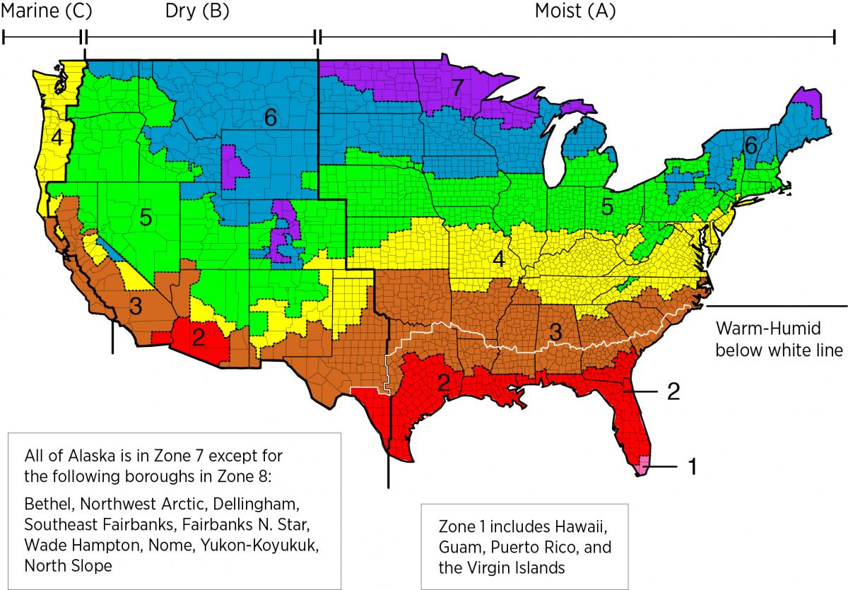
Figure 1. Climate Zone Map from IECC 2009, 12, 15, and 18. (Source: 2012 IECC)

Figure 2. Climate Zone Map from IECC 2021. (Source: 2021 IECC)
The insulation levels should be based on the minimum requirements for vapor control in the current adopted building code and the minimum requirements for thermal control in the current energy code. Table 1 provides the minimum thermal resistance (R-value) requirements specified in the 2009 IECC (ICC 2009b) and the 2012 IECC (ICC 2012b) based on climate zone for roof assemblies.
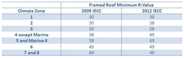
Table 1. Attic Insulation Requirements in the 2009 and 2012 IECC. (Source: 2009 IECC and 2012 IECC)
It is important to maintain a sufficient ratio of exterior insulation to total roof assembly insulation. In colder climate zones, the amount of exterior (rigid) insulation needed to avoid condensation problems increases. Table 2 provides information on minimum levels of air impermeable insulation for condensation control specified in Table R806.4 Insulation for Condensation Control of the 2009 IRC (ICC 2009a) and Table R806.5 Insulation for Condensation Control of the 2012 IRC (2012a).
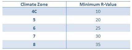
Table 2. Insulation required for Condensation Control in the 2009 and 2012 IRC. (Source: 2009 IRC and 2012 IRC)
Training
Compliance
More
More Info.
Access to some references may require purchase from the publisher. While we continually update our database, links may have changed since posting. Please contact our webmaster if you find broken links.
The following authors and organizations contributed to the content in this Guide.
Building Science Corporation, lead for the Building Science Consortium (BSC), a DOE Building America Research Team