

Scope
Use termite-resistant design and materials when constructing new homes in areas at high risk for termites to minimize the threat of termite damage and to minimize the need for pesticides. Design foundation assemblies that reduce the likelihood of termite entry while maintaining the water, air, vapor, and thermal control layers of the home’s thermal envelope.
- Minimize attractants like food and water.
- Minimize the need for joints and expansion joints when designing foundation slabs.
- Minimize the likelihood of cracks in the concrete.
- Install metal mesh or sand/basalt termite barriers around the foundation.
- Seal around all utilities that go through the slab.
- Use termite-resistant construction materials.
- Install termite shields between the slab or stem wall and the sill plate.
- Provide inspectability.
See the Compliance Tab for links to related codes and standards and voluntary federal energy-efficiency program requirements.
Description
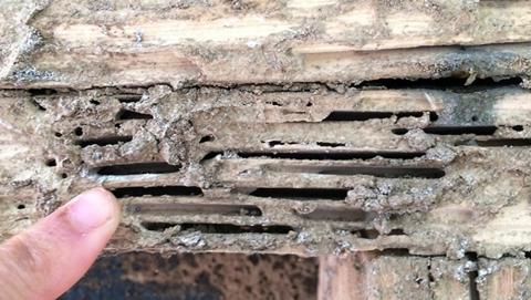
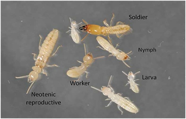
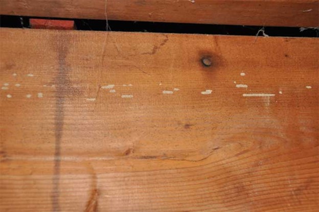
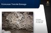
Termites are a major threat to the structural integrity of homes (Figure 1). New and existing homes need to be connected to their foundations in a manner that withstands termite activity. Additionally, homes can be constructed and renovated with termite-resistant framing and insulation. The termite design approach should be complimentary to approaches taken to increase the thermal efficiency of the home.
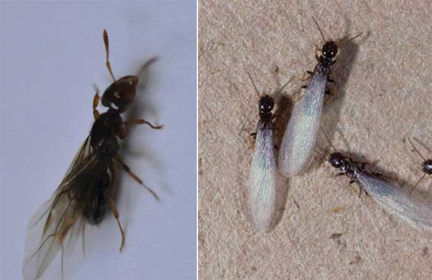
The recommendations contained in this guide are directed toward subterranean termites, not dry wood termites which can fly. These recommendations are intended to minimize the need for chemical soil treatment; however, some chemical soil treatment may still be necessary in some circumstances.
There are many steps builders can take to reduce the likelihood of future termite entry and damage to homes. Several of those are listed below. This guide also includes sample foundation designs for basement, crawlspace, and slab-on-grade foundations that show how termite-resistant measures can integrate with thermal envelope control layers for water, air, thermal, and vapor control in building assemblies.
Steps to Reduce the Likelihood of Termite Infestations
It is easier and cheaper to prevent termite infestations than to treat them once termites have taken up residence in a home. Many of those steps are summarized here and discussed in greater detail below or in other guides as linked. Most of these recommendations come from the report Pest Prevention by Design, written by Chris Geiger and Caroline Cox with input from a technical advisory panel of exterminators, agricultural extension offices, and government researchers and published by the San Francisco Department of the Environment and the International Code Council (Geiger and Cox 2012).
Minimize Attractants like Food and Water
Damp wood attracts termites.
- Keep the house and ground around it dry.
- Do not over irrigate and do not let irrigation spray the house. Direct surface water away from foundation perimeters by sloping ground away from the house and installing footing drain pipe that drains away from the home.
- Control rain runoff from roof assemblies with gutters that drain to a low point or drywell away from the house to prevent rainwater from saturating the ground adjacent to the foundation perimeters.
- Maintain space between the ground and wood framing.
- Establish a minimum clearance of 18 inches between wood foundation components (beams or joists) and soil in crawlspaces. In areas of high termite hazard, clearance between beams or joists and soil should be 36 inches.
- Siding should be at least 6 inches from the soil, 8 or 12 inches is preferable. Crawlspace vents should be at least 6 inches above soil. Crawlspace vents should be covered with #50 bronze mesh between layers of ½ to 1-inch mesh to keep out termites and ants.
- Remove wood and cellulose debris around the structure after construction.
- Don’t bury wood scraps, form boards, vegetation, stumps, large dead roots, cardboard, or trash within fifty feet of the building.
- Install fill material around structures that is clean and free of vegetation and cellulose material.
- When constructing with concrete masonry units, remove any plant debris or paper in block cells before use.
- After all foundation work is completed, remove all loose wood and wood debris from the crawl space and around the perimeter of the building.
- Consider installing a 2-foot perimeter of crushed rock, pea gravel, concrete, or concrete pavers around the home instead of wood mulch or vegetation, as described in the guide “Pest-Resistant Ground Cover at Foundation Perimeter.”
- Advise the homeowner to keep plants, trees, wood mulch, and wood piles away from the house.
Minimize the Need for Joints and Expansion Joints When Designing Foundation Slabs
One study found 83% of subterranean termites entering buildings came in through expansion joints in concrete slabs.
-
- Pour concrete patios as part of the main slab if possible, rather than separating the patio from the main slab with a joint.
- If expansion joints are used, provide inspection access and install termite-resistant mesh or sand barriers at the joints.
- Mesh barriers should be laid on top of the vapor barrier and the mesh fabric should have a 0.6 inch (15 mm) accordion fold under the joint. The edges of the mesh should be turned up 1 inch (25 mm) to be cast into the slab. The accordion fold should be protected by a strip of vapor barrier material so that the concrete does not bond to the accordion fold. Alternatively, a mesh barrier with an accordion fold can be parged to the top of the slab.
- Sand barriers (graded stone) should be confined within a void adjoining the joint that is at least 3 inches (75 mm) deep and at least 2 inches (50 mm) wide. A retainer cast into the slab should be used to confine the sand particles.
Minimize the Likelihood of Cracks in the Concrete
- Cure concrete slabs slowly to reduce shrinkage and cracks, minimum seven days or as recommended by a structural engineer.
- For foundations and slabs up to about 50 feet in dimension, use liberal applications of topical curing compounds to decrease cracking.
- For foundations of 50 to 100 feet, use adequate concrete reinforcing and proper concrete mix design, placement, finishing, and curing techniques, and use a shrinkage limiting concrete admixture.
- For slabs over 100 feet in dimension use a properly designed, shrinkage compensating concrete admixture.
- Construct interior concrete slabs with reinforcing 6 x 6 in. welded wire fabric, or the equivalent.
- Embed anchor bolts in slabs or stem walls as the concrete is poured. If additional anchors are necessary, use adhesive anchoring systems rather than expanding fasteners to avoid causing cracks.
- Mechanically compact concrete with a vibrator to minimize voids in concrete slabs.
Install Metal Mesh or Sand/Basalt Termite Barriers Around the Foundation
- Install metal mesh barriers for termite exclusion around foundations:
-
- as a perimeter barrier for masonry exterior walls (parge to the concrete slab, drape across the cavity, then build into the exterior wall)
- or as a continuous barrier under concrete slabs,
- or as a barrier under joints and for utility penetrations.
- Use mesh made from grade 304 or 316 wire with a minimum diameter of 0.01 inches (0.18 mm) and a maximum aperture size of 0.02 inches x 0.01 inches (0.66 mm x 0.45 mm, or smaller if local termite species are known to be small).
- Parge the mesh to the concrete foundations with a grout consisting of water-dispersed copolymer, Type GP Portland cement, and sieved aggregate that can pass through the stainless steel mesh.
- Keep the mesh from contact with dissimilar metals that would produce a corrosion reaction.
- If pieces of mesh need to be joined, make the joint 0.4 to 0.6 inches (10 to 15 mm) wide where the edges of the two pieces are folded together 2.5 times or a parged area 1.4 inches (35 mm) wide where the pieces overlap.
-
- Install sand or basalt barriers for termite exclusion:
-
- as a perimeter barrier in wall cavities – install particles to a depth of 3 inches (75 mm)
- as a perimeter barrier in a trench around the foundation - install particles to a depth of 3 inches (75 mm) and a width of at least 3.93 (100 mm)
- or as a continuous under-slab barrier – install to a depth of 3 – 4 inches (75-100 mm) deep and compact with a vibrating plate-type tamper
- or as a barrier under joints and around utility penetrations.
-
- Use particles of sand or basalt that are graded and shaped so that a sufficient proportion of them are of a size that is too large to be transported by local termite species and such that voids between particles are not large enough to permit penetration by local termite species. Appropriate diameters for particles are
-
- 0.04 – 0.06 inches (1.2-1.7 mm) for the western subterranean termite
- 0.06 - 0.11 inches (1.7-2.8 mm) for the eastern subterranean termite
- 0.06 - 0.09 inches (1.7-2.4 mm) for the Formosan termite.
- The particles can be either igneous or metamorphic stone with a wet/dry analysis showing less than 35% variation and their specific gravity must be at least 2.52
-
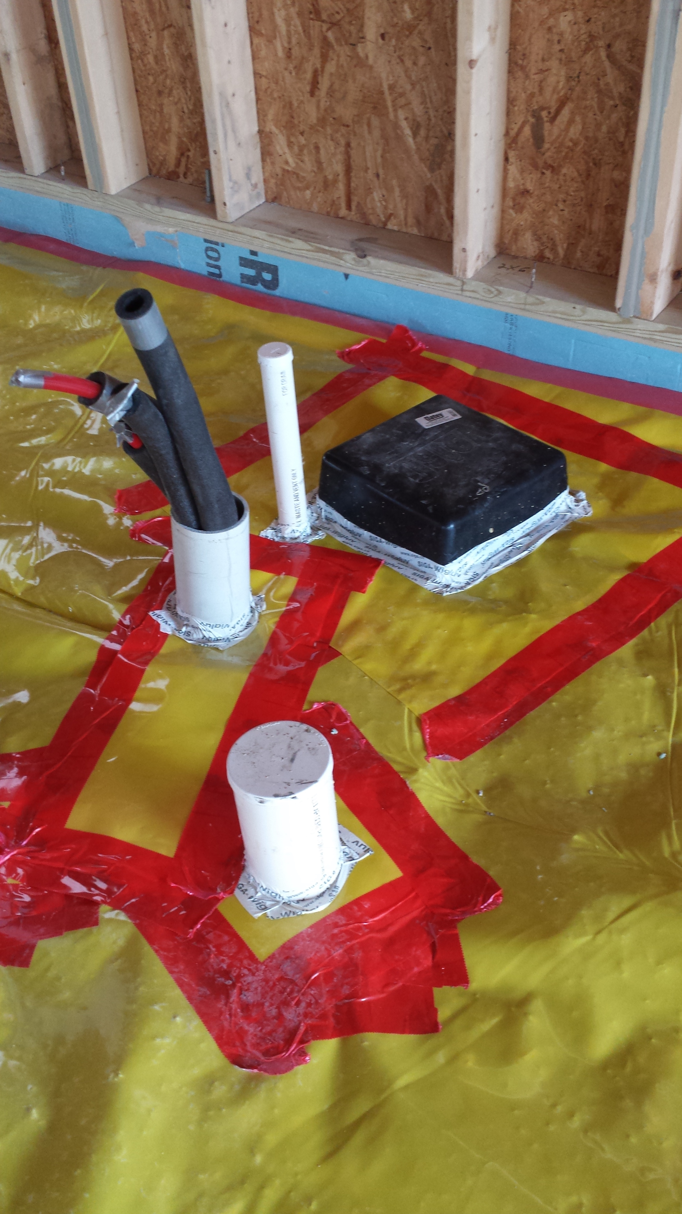
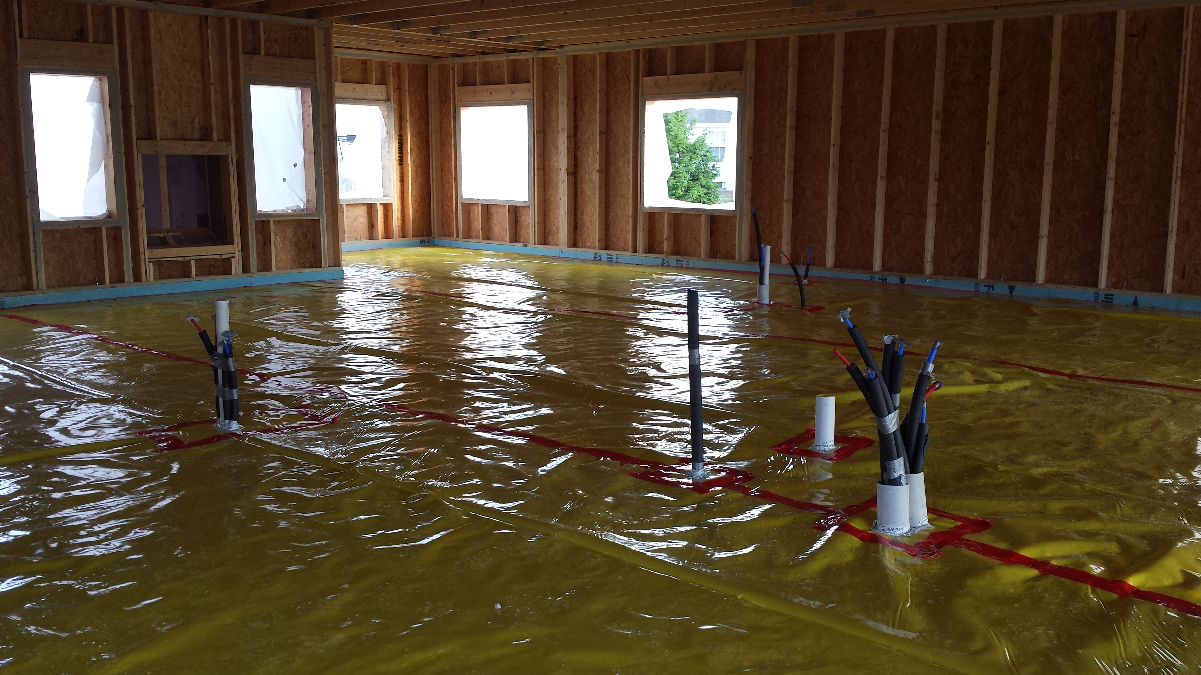
Seal around all Utilities that Go through the Slab
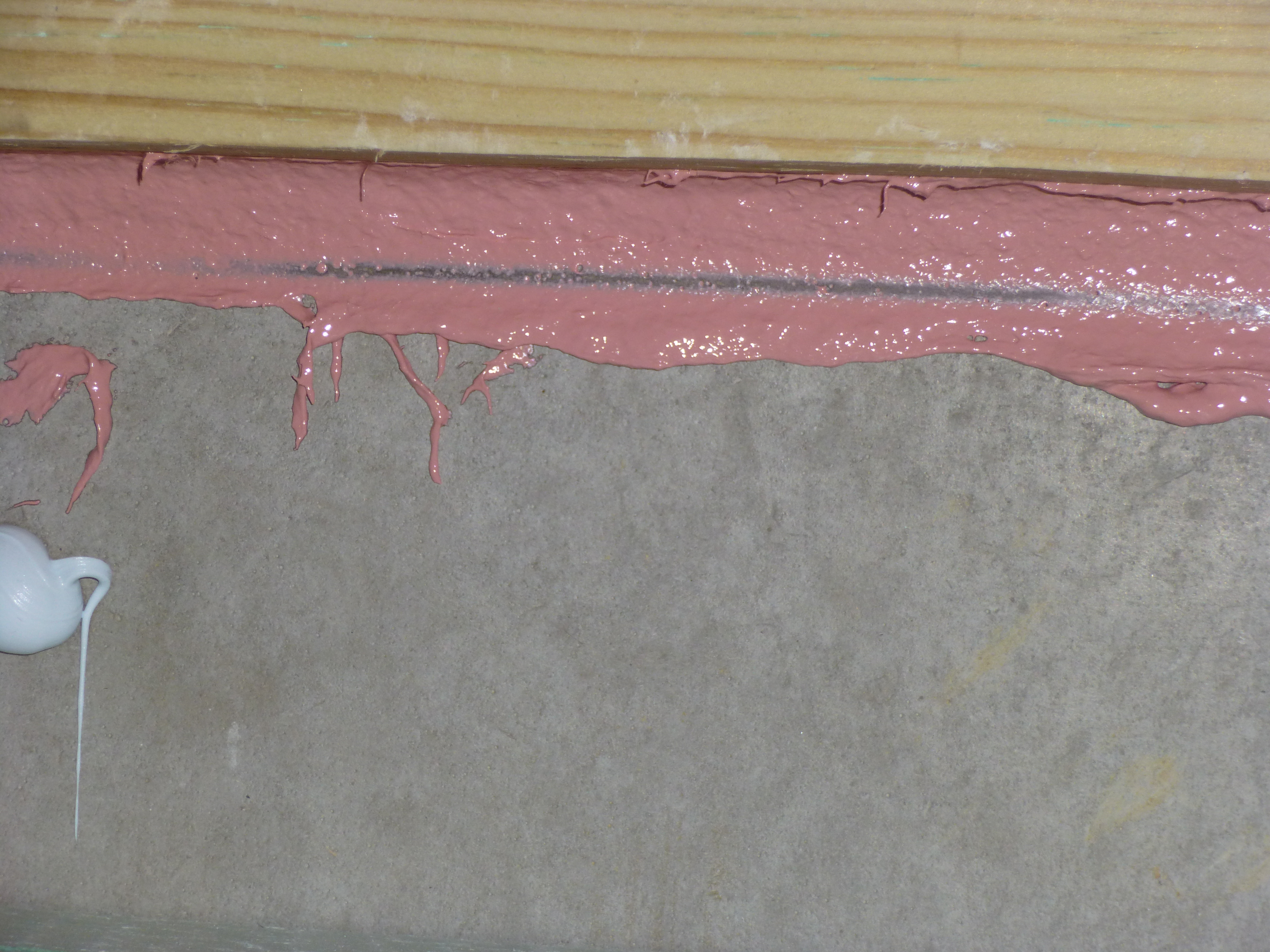
- Seal the gaps around pipes or conduit using epoxy as a sealant, mesh barriers, or sand barriers.
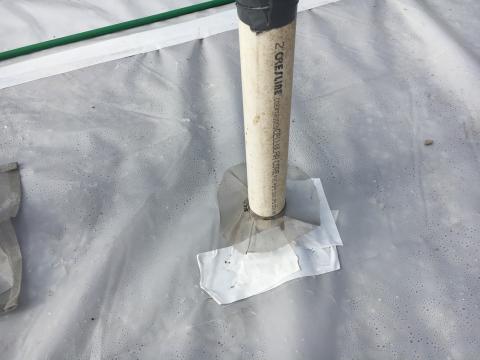
- If using metal mesh barriers, the barrier should consist of a flange of stainless steel or copper mesh 2 inches (50 mm) wide that is attached to the pipe with a stainless steel clamp and then embedded in the slab or parged to the top surface of the slab. (See Figure 2.)
- For sand barriers, concrete should be poured in a circular area 1 inch (25 mm) around the utility pipe. The void should then be filled with sand at least 3 inches (75 mm) deep. The sand should be capped at the top of the slab, and a retainer cast into the slab below the sand should be used to prevent sand loss beneath the slab.
Use Termite-Resistant Construction Materials
- Use steel posts for post-and-beam foundations; seal both ends of the posts with welded plates and set posts in concrete foundations.
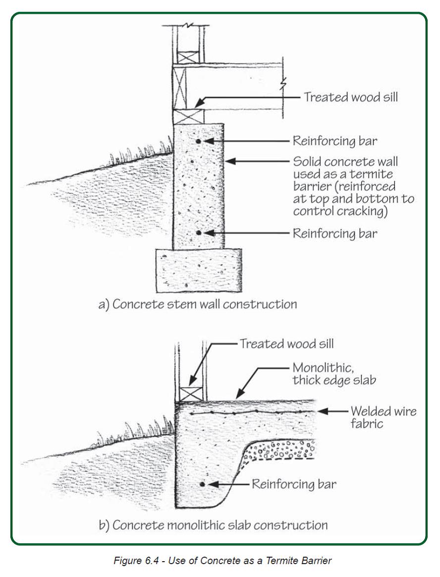
- For foundation walls use solid concrete or masonry with a top course of solid block, bond beam, or concrete-filled block and steel reinforcing rods to reduce cracking.
- For sill plates, use preservative-treated wood.
- Use borate-treated lumber, rigid foam, and cellulose insulation (see more on borate treatment in the section below).
- Use termite-resistant framing materials including steel, brick, concrete, stone, and the heartwood of naturally pest-resistant woods such as western red cedar, redwood, incense cedar, Port Orford cedar, black locust, northern white cedar, and Alaska cedar.
- Use termite-resistant sheathing and siding includes aluminum, steel, rigid plastics, gypsum, wood-plastic composites, and fiber cement.
- Use naturally termite-resistant insulation including mineral wool.
- Avoid subgrade rigid foam insulation on the foundation or protect rigid foam insulation from ground contact with PVC, metal flashing, parging, vapor barrier, etc. If ground contact cannot be avoided and as standard practice in high-termite risk locations, install termite shields between insulation and sill plates.
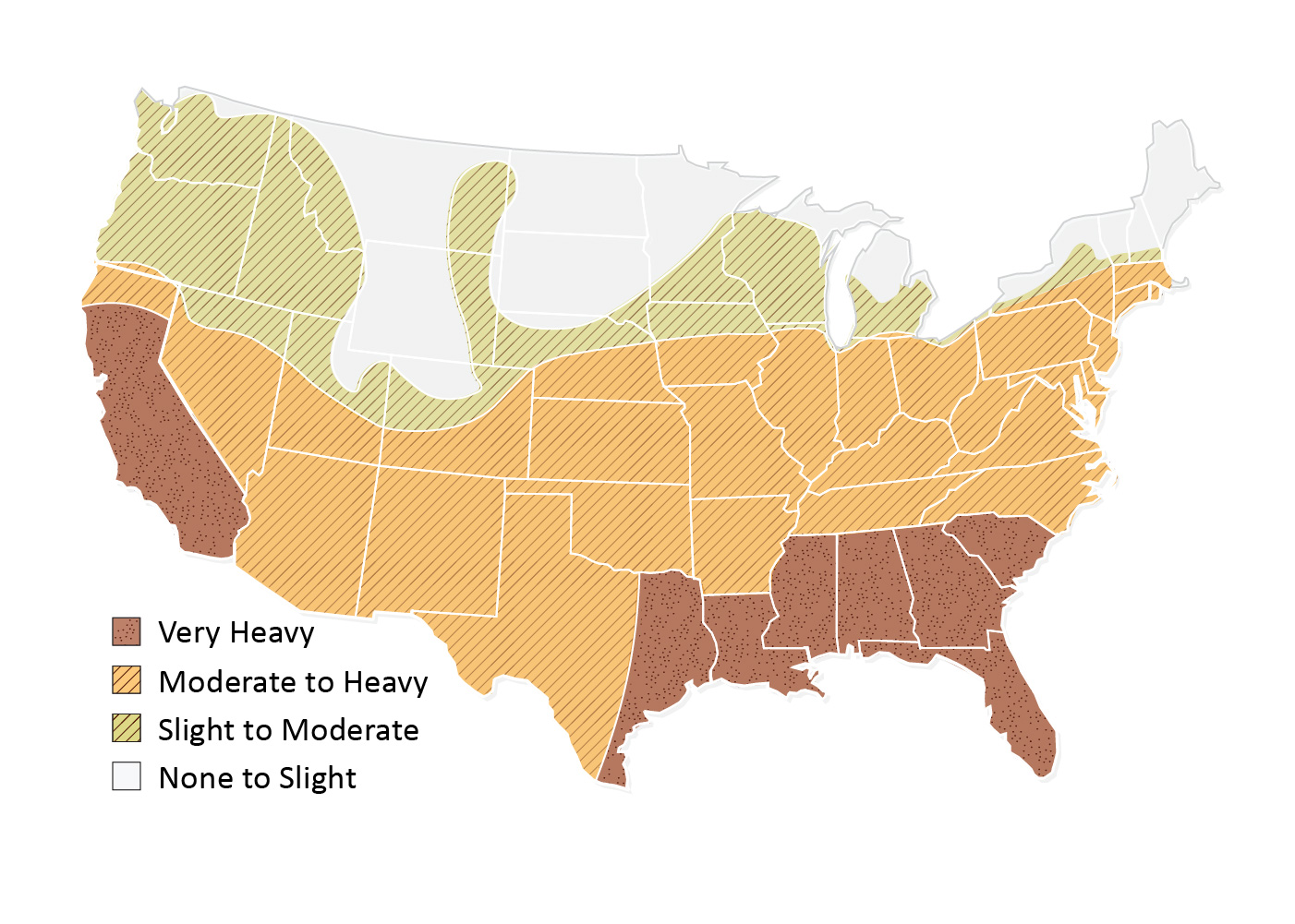
- In areas classified as “Very Heavy” on the termite infestation probability map (i.e., Alabama, Florida, Georgia, Louisiana, Mississippi, South Carolina and parts of California and Texas), foam plastic insulation should not be installed on the exterior face of below-grade foundation walls or under slabs.
- Foam plastic insulation installed on the exterior of above-grade foundation walls should be kept a minimum of 6 in. above the final grade and should be covered with moisture-resistant, pest-proof material (e.g., fiber cement board or galvanized insect screen at the bottom-edge of openings).
- Inspection strips (min 3 inches) should be provided on the interior of foundation walls if foam plastic insulation is installed.
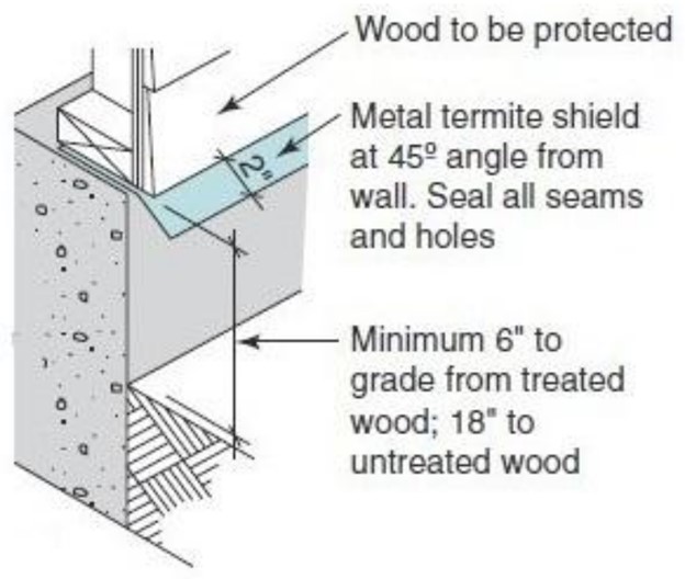
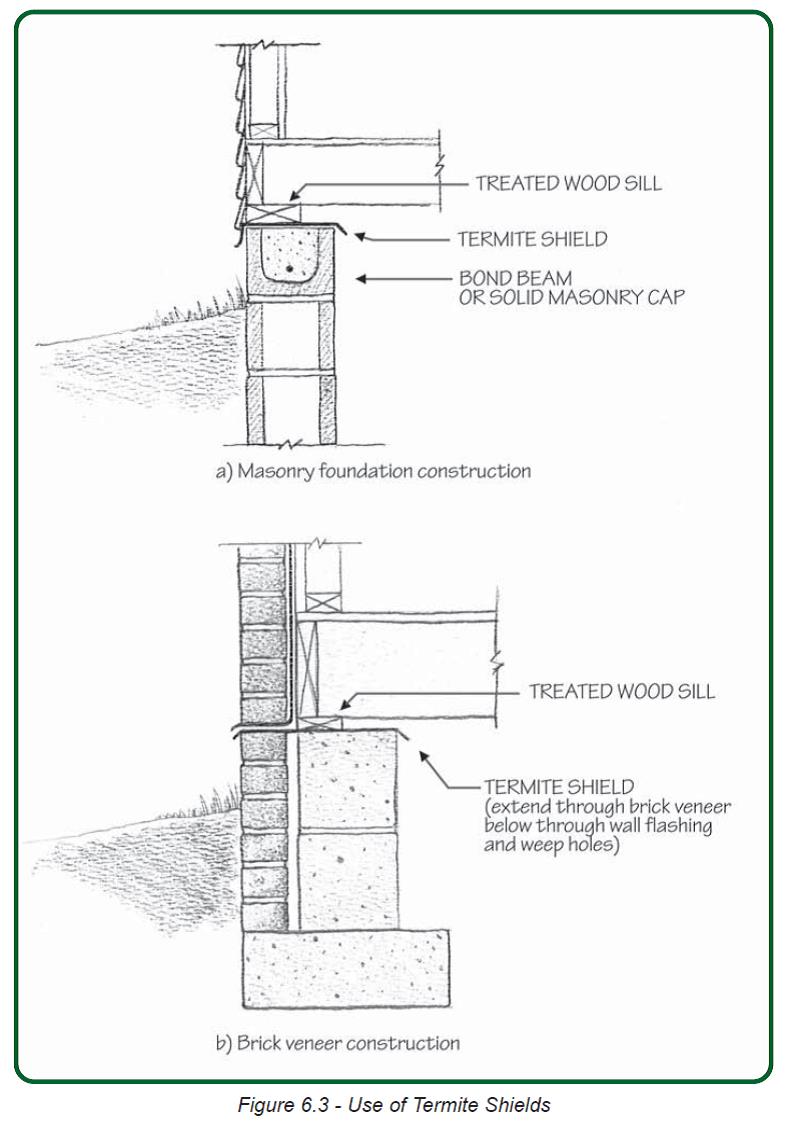
Install Termite Shields between the Slab or Stem Wall and the Sill Plate
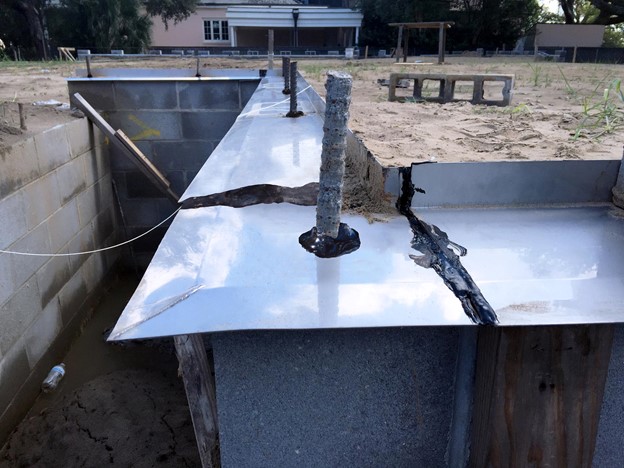
- Shields should extend out 2.75 - 3.14 inches (70-80) mm from the foundation. The last 1.81 inches (30 mm) of the shield should be bent downward at a 45-degree angle. (See Figures 3 and 4.)
- Termite shields should be constructed of
- galvanized steel at least 0.02 inches (0.5 mm) thick
- sheet copper at least 0.01 inches (0.4 mm) thick
- stainless steel at least 0.01 inches (0.4 mm) thick
- aluminum alloy at least 0.02 inches (0.5 mm) thick
- copper and zinc alloys at least 0.02 inches (0.5 mm) thick
- or woven stainless steel mesh.
- Joints and corners should be mitered and soldered, welded, or brazed.
- Corners should be rounded.
- Ensure that the metal is chemically compatible with the treated wood sill plate (some post 2004 non-arsenic wood treatments are corrosive to steel), or install sill seal or peel and stick membrane between the termite shield and the wood sill plate to prevent the metal from corroding.
Provide Inspectability
- Install termite shields between foundations and framing. The metal flange may stop termites and will increase their visibility if they are able to cross it.
- When installing rigid foam on the interior or exterior of foundation walls. Include strips of removable insulation at the top of exterior foundation walls (see Figure 9 below) and leave a gap in insulation at the top of interior foam insulated crawlspace and basement walls (See Figure 7). Consider painting the wall at the gap white for increased visibility.
- Construct homes with foundation walls (non-wood covered) extending at least 8 inches above grade; 12 inches is better to compensate for future mulching by homeowners. This improves inspectability and increases the distance between the ground and wood framing.
- Provide inspection access to expansion joints, penetrations through slab, behind HVAC equipment, etc.
- Allow inspection for termites by providing at least 6 inches of clearance between the side of the house and accessory wooden structures like decks, fences, patios, and planters. If this clearance is not possible, construct accessory structures so that they are easily removable to allow inspection for termites.
Use Borate-Treated Materials
Borate has pesticide, fungicide, and fireproofing properties. It is not harmful to humans but is toxic to termites and other bugs so they will avoid ingesting it. Borate-treated lumber and rigid foam insulations are available. Borate is routinely added to cellulose insulation as a fire retardant. Borate treatment for lumber involves penetrating (pressure-treated) methods and surface (topical) methods, depending on the material (see Figure 5). Borate-treated lumber framing is recommended for use in “heavy” termite infestation regions. Such regions are defined in the International Residential Code (IRC) in Figure R301.2(7) (2018) “Termite Infestation Probability Map,” shown on the Climate tab. In such regions, penetrating (pressure-treated) borate lumber is recommended. While heat and humidity will not impact borate’s effectiveness, borate-treated lumber should be protected from liquid water to prevent leaching of the borate treatment. Exposed treated framing will lose its efficacy over time. Borated-treated lumber framing should not be exposed to rain and should not be used in ground contact or below grade.
Borate-treated cavity insulations such as cellulose are not likely to be exposed to rain and therefore have little risk of leaching of the borate treatment. Borate-treated cellulose is recommended in “heavy” termite infestation regions. Inherently termite-resistant cavity insulations such as mineral wool could also be used. Borate-treated expanded polystyrene (EPS) can experience leaching when used below grade or in ground contact. However, the EPS can be protected from liquid water leaching with the use of drainage membranes or capillary breaks. In all cases, all ground contact rigid insulations, including borate-treated EPS, should be employed in conjunction with termite shields. Borate-treated EPS that is used above grade as continuous exterior insulation is typically protected by back ventilated and drained cladding assemblies and therefore presents low risk of leaching of the borate treatment.
Termite-Resistant Designs
Most damage to buildings caused by termites can be avoided by preventing the entry of termites where the buildings are connected to the ground. This guide provides some suggested examples of termite-resistant foundation assemblies for basement, crawlspace, and slab-on-grade foundations that incorporate borate-treated lumber and insulation into the wall and foundation’s control layers. These control layers, which provide the environmental separation in the home’s thermal envelope, consist of the water, air, vapor, and thermal control layers. In some foundation and wall assemblies, one product serves as more than one control layer. In some cases, the layer is borate treated; in other cases, it works in conjunction with borate-treated materials to provide for both the home’s thermal efficiency and termite resistance. Note the four foundation options shown here all include below-grade foundation insulation; this may or may not be required or desired in your climate zone.
Basement Foundations
Termite Resistance
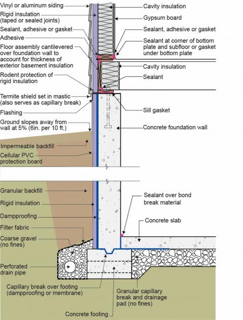
Figure 6 illustrates a wood-framed building on a concrete basement foundation. The wood framing is insulated on the exterior as is the concrete basement foundation. The wood framing is borate treated. The continuous exterior insulation on the wood framing is borate-treated expanded polystyrene (EPS). Alternatively, the continuous exterior insulation can be mineral wool. The cavity insulation is borate-treated cellulose. The exterior basement foundation insulation is borate-treated expanded polystyrene (EPS). It is protected from groundwater leaching by the granular backfill connected to an exterior perimeter drain. The grade slopes away from the home and the top few inches are “capped” with impermeable backfill.
All exterior basement foundation insulations can act as a pathway for termite entry. The use of stainless steel termite shields set in mastic and sealed to the top of the foundation wall address this pathway. The joints in the termite shield need to be overlapped and sealed. The termite shield needs to extend outward past the exterior edge of the exterior basement foundation insulation and its associated protection layer a minimum of ¾ inch to impede the ability of termites to bridge the shield. This also facilitates visual inspection of the effectiveness of the termite shield.
Note that continuous exterior insulation also needs to be protected from rodents and insects – particularly at the bottom of frame wall and floor assemblies. In Figure 6, rigid formed PVC plastic cover board is installed over the foundation wall and extends several inches below grade. “Bent” sheet metal flashing is wrapped around the bottom end of the rigid foam on the above-grade exterior EPS insulation.
Thermal Efficiency
Figure 6 also illustrates the environmental separation aspects of basement foundations.
A continuous water control layer controlling rainwater is installed on the exterior of the wall – taped and sealed rigid insulation (EPS). Rigid EPS also provides a continuous water control layer on the exterior of the basement foundation.
The continuous air control layer is provided by the sealed, taped EPS on the exterior of the above-grade wall and the concrete foundation wall.
Vapor control is provided by controlling the temperature of the wall assembly condensing surface by installing the continuous exterior insulation. Vapor control of the concrete foundation is provided by installing dampproofing on the exterior of the foundation wall and by installing dampproofing or sheet polyethylene between the footing and stem wall and under the foundation slab.
Thermal control is provided by the EPS continuous insulation on the exterior of the above-grade and foundation walls and the borate cavity insulation.
This approach works in all climates.
Crawlspace Foundations
Termite Resistance
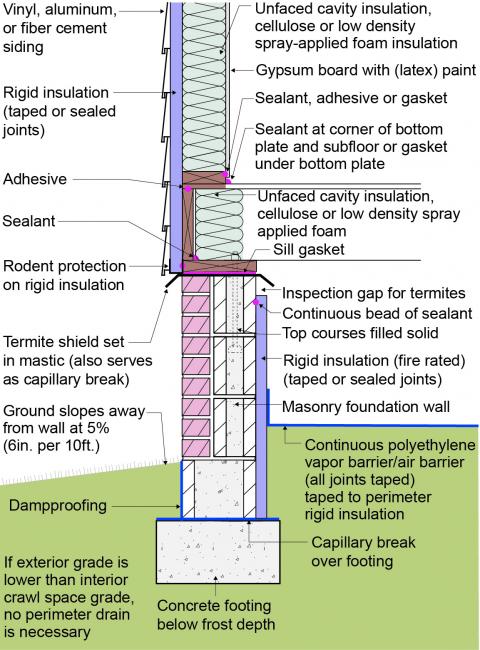
Figure 7 illustrates a wood-framed building on a crawlspace foundation that is insulated on the interior of the foundation wall and the exterior of the above-grade wall. The wood framing is borate treated. The continuous exterior insulation on the wood framing is borate-treated expanded polystyrene (EPS). Alternatively, the continuous exterior insulation can be mineral wool. The cavity insulation is borate-treated cellulose. The interior crawlspace foundation insulation is borate-treated expanded polystyrene (EPS).
Interior crawlspace insulation can act as a pathway for termite entry. The use of stainless steel termite shields set in mastic and sealed to the top of the foundation wall address this pathway. The joints in the termite shield need to be overlapped and sealed. The termite shield needs to extend outward and inward past the edges of the crawlspace foundation structural wall a minimum of ¾ inch to impede the ability of termites to bridge the shield. An inspection gap should be provided at the top of the interior crawlspace insulation. This gap should remain open for the life of the building.
Note that continuous exterior insulation also needs to be protected from rodents and insects, particularly at the bottom of frame wall and floor assemblies. “Bent” sheet metal flashing is wrapped around the bottom end of the rigid foam on the above-grade exterior EPS insulation.
Thermal Efficiency
Figure 7 also illustrates the environmental separation aspects of crawlspace foundations. The crawlspace in Figure 7 is an unvented conditioned crawlspace.
A continuous water control layer of taped and sealed rigid EPS insulation is installed on the exterior of the wall to controlling rainwater and is connected to the continuous water control layer on the exterior of the crawlspace foundation. Note that the crawlspace foundation wall above grade is a mass wall assembly consisting of concrete masonry units.
The continuous air control layer is provided by the sealed, taped EPS on the exterior of the above-grade wall. This is connected to the top of the crawlspace foundation wall, which is in turn connected to the interior rigid insulation that is acting as the foundation air control layer.
Vapor control is provided by controlling the temperature of the wall assembly condensing surface by installing the continuous exterior insulation. Vapor control of the crawlspace foundation is provided by installing damp proofing on the exterior of the crawlspace foundation wall, the rigid insulation on the interior of the crawlspace foundation wall, and a sheet polyethylene interior ground cover.
Thermal control is provided by installing the continuous exterior insulation and cavity insulation. Additionally, rigid insulation is installed on the interior of the crawlspace foundation wall.
This approach works in all climates.
Slab on Grade Foundation with a Masonry Stem Wall and a Thermally Uncoupled Concrete Slab
Termite Resistance
Figure 8 illustrates a wood-framed building on a slab-on-grade foundation constructed using a masonry stem wall with a thermally uncoupled concrete slab. The concrete slab is cast over a layer of rigid insulation that is “turned up” at the perimeter to provide a thermal break. The rigid insulation under the slab is borate-treated expanded polystyrene (EPS). It is protected from groundwater leaching by the granular capillary break. Under-slab insulation may not be required or desired in your climate zone. The wood framing of the above-grade wall is borate treated. The continuous exterior insulation on the wood framing is borate-treated expanded polystyrene (EPS). Alternatively, the continuous exterior insulation can be mineral wool. The cavity insulation is borate-treated cellulose.
This slab-edge insulation can act as a pathway for termite entry. The use of stainless steel termite shields set in mastic and sealed to the top of the masonry stem wall spanning the insulation thermal break and subsequently sealed to the slab edge addresses this pathway. The joints in the termite shield need to be overlapped and sealed. The termite shield needs to extend outward and inward past the edges of the crawlspace foundation structural wall a minimum of ¾ inch to impede the ability of termites to bridge the shield. This also facilitates visual inspection of the effectiveness of the termite shield.
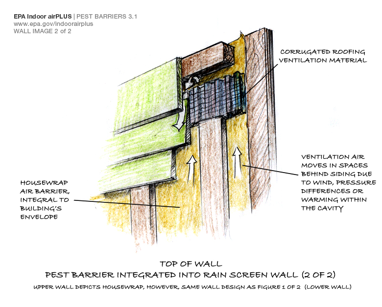
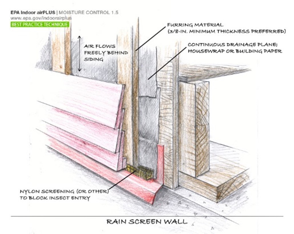
Note that continuous exterior insulation on the frame wall also needs to be protected from rodents and insects (see Reduce Pest Intrusion), particularly at the bottom of frame wall and floor assemblies. “Bent” sheet metal flashing is wrapped around the bottom end of the rigid foam on the above-grade exterior EPS insulation. Further note that the gap created by the wood furring needs to be protected from insect intrusion at the bottom of the cladding. A plastic mesh wrapped in an insect screen serves this function.
Thermal Efficiency
Figure 8 also illustrates the environmental separation aspects of a slab-on-grade foundation constructed using a masonry stem wall with a thermally uncoupled concrete slab.
A continuous water control layer controlling rain water is installed on the exterior of the above-grade wall consisting of taped and sealed rigid insulation. This is connected to the continuous water control layer on the exterior of the brick masonry stem wall foundation. Note that the stem wall foundation wall above grade is a mass wall assembly.
The continuous air control layer is provided by the sealed, taped rigid insulation on the exterior of the above-grade wall, which is connected to the top of the stem wall foundation wall, which is in turn connected to the interior concrete slab on grade, which is connected to the slab which acts as an air control layer.
Vapor control is provided by controlling the temperature of the above-grade wall assembly condensing surface by installing the continuous exterior insulation. Vapor control of the interior concrete slab on grade is provided by installing a sheet polyethylene vapor barrier in direct contact with the underside of the concrete slab.
Thermal control is provided by installing continuous insulation on the exterior of the above-grade walls along with the cavity insulation. Additionally, rigid insulation is installed under the concrete slab and “turned up” at the perimeter to perform as the thermal break
This approach works in all climates.
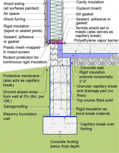
Slab-on-Grade Foundation with a Monolithic Concrete Slab/Grade Beam
Termite Resistance
Figure 9 illustrates a wood-framed building on a slab-on-grade foundation constructed using a monolithic concrete slab/grade beam. Note the “turned down” portion of the concrete slab at the perimeter. This “turned down” section acts as the “grade beam.” The wood framing is borate treated. The continuous exterior insulation on the wood framing is borate-treated expanded polystyrene (EPS). Alternatively, the continuous exterior insulation can be mineral wool. The cavity insulation is borate-treated cellulose. The monolithic concrete slab/grade beam is insulated at the perimeter with exterior rigid insulation. The exterior rigid insulation is borate-treated expanded polystyrene (EPS). It is protected from groundwater leaching by the granular backfill connected to an exterior perimeter drain.
Exterior slab edge insulation can act as a pathway for termite entry. The use of stainless steel termite shields set in mastic and sealed to the top of the monolithic concrete slab/grade beam address this pathway. The joints in the termite shield need to be overlapped and sealed. The termite shield needs to extend outward past the exterior edge of the exterior slab edge insulation and its associated protection layer a minimum of ¾ inch to impede the ability of termites to bridge the shield. This also facilitates visual inspection of the effectiveness of the termite shield. Additionally, a removable strip of insulation and protection board is installed to provide an inspection gap.
Note that continuous exterior insulation on the frame wall also needs to be protected from rodents and insects, particularly at the bottom of frame wall and floor assemblies. Rigid formed PVC plastic cover board is installed over the foundation wall and extends several inches below grade. “Bent” sheet metal flashing is wrapped around the bottom end of the rigid foam on the above-grade exterior EPS insulation. Figure 9 also shows a 2-foot perimeter of pea gravel or crushed stone as a pest barrier bordering the home.
Thermal Efficiency
Figure 9 also illustrates the environmental separation aspects of a slab-on-grade foundation constructed using a monolithic concrete slab/grade beam insulated on the exterior slab edge.
A continuous water control layer of taped and sealed rigid EPS insulation is installed on the exterior of the wall to control rain water. This is connected to the rigid EPS that provides the continuous water control layer on the exterior of the monolithic slab/grade beam.
The continuous air control layer is provided by the sealed taped EPS installed on the exterior of the above-grade wall and is connected to the top of the monolithic slab/grade beam concrete slab, which is acting as the slab air control layer.
Vapor control is provided by the EPS exterior insulation which controls the temperature of the wall assembly condensing surface. Vapor control of the monolithic slab/grade beam concrete is provided by installing a sheet polyethylene vapor barrier in direct contact with the underside of the concrete slab and wrapping under the grade beam.
Thermal control is provided by installing the EPS on the exterior of the above-grade and foundation walls as well as the cavity insulation.
Ensuring Success
Consult a licensed architect or engineer to develop the detailed approach for homes to withstand termite activity. The termite resistance design can occur in conjunction with thermal efficiency where the approaches are complimentary rather than incompatible.
Region
The Termite Infestation Probability Map shown below (from the IRC Figure R301.2(7)) shows the likelihood of termite infestation across the United States. Consult your local code for termite requirements in your location (see Compliance tab).
Training
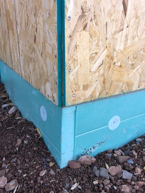
Right and Wrong Images
Source
A fact sheet providing information on termite species and how to prevent them from entering into your home.
Source
A fact sheet providing information on termite species and how to prevent them from entering into your home.
Source
A fact sheet providing information on termite species and how to prevent them from entering into your home.
Source
A fact sheet providing information on termite species and how to prevent them from entering into your home.
Source
Source
Source
Source
Source

Source
Source
Source
Source
Source
Source
Videos
Compliance
Retrofit
Many of the measures described in this guide for new homes can also be applied to making the foundations of existing homes more resistant to termites.
Some more important measures include:
- Ensure good surface water management practices are in place to help keep soil around the home dry.
- Avoid wood mulch around the foundation. Remove wood debris and plants from around foundations. Store word piles 20 feet or more from the home.
- Repair all cracks in concrete foundations promptly.
- Consider using borate-treated cellulose or termite-resistant fiberglass when adding insulation to walls.
- Add a pest inspection strip if rigid insulation is added on the interior or exterior foundation walls.
- Consider borate-treated framing for additions and repairs. Soil pest abatement methods may be needed. If termites are seen, consult a pest exterminator.
More Info
References and Resources
*For non-dated media, such as websites, the date listed is the date accessed.
Contributors to this Guide
The following authors and organizations contributed to the content in this Guide.
Questions? Comments? Contact our webmaster.