

What this tool does
The tool calculates a single R-value for an area made up various materials with distinct R-values. This method assumes that heat flows through each of these distinct areas independently (in parallel), as opposed to flowing from one to the other.
Calculated values
- Total area.
- Equivalent Total R-value.
- Equivalent total U-factor.
- Equivalent UA – the U-factor multiplied by the total area.
Tips
- Clicking the label for any input or result will cause a popup help box to appear. This help box includes the allowed and normal values (for inputs).
- You may select from two to ten distinct areas for your subject building section. Merely click on the drop-down menu next to “Number of areas” to make your choice. Notice that each drop-down row has space for you to enter “Area” and its corresponding “R-value”.
- Your choice for “Number of areas” and the rows you fill in must match; if you leave a row blank for “Area” and “R-value”, the tool will not calculate your answer until you fill in the blank row or reduce the “Number of areas” to the number of filled-in rows.
- If you fill in a row, but then reduce the “Number of areas” so that the last filled-in row disappears, the values in that invisible row are NOT used in the calculation.
- The term “whole-wall” is sometimes used in place of “parallel-path”. Of course, this tool may be used for walls, ceilings, floors, or other appropriate building areas.
- This tool is intended for wood framing only. Do not use it for metal framing.
Example
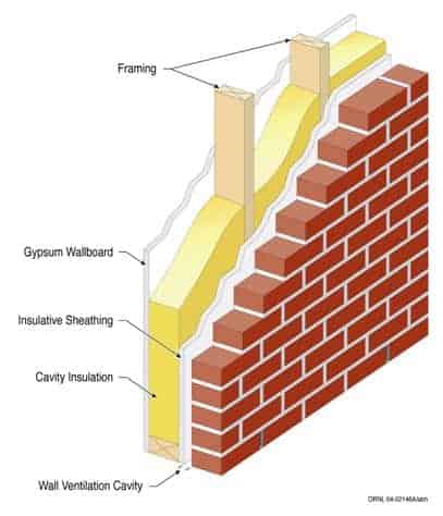
Using the illustration above and the details in the table below, let’s run through an example using the Parallel-Path Equivalent R-Value tool. The illustrated wall has only two areas with distinct R-values; the area through the insulation and the area through the framing, so set the “Number of areas” to 2. Let’s assume the wall is framed with 2x6s and the insulation between the framing members is fiberglass batt. For simplicity, we will also assume that the brick veneer has no impact on the R-value because of the ventilation cavity that separates it from the wall sheathing. These details are listed in the table below.
Assume the total wall area we are looking at is 1000 square feet (our apologies to those using the metric system). From the table above, the wall framing percentage is listed as 25.4% (Please see Carpenter, Stephen C., “Characterization of Framing Factors for Wood–Framed Low–Rise Residential Buildings” ASHRAE Transactions Feb. 2003: v 109, Pt 1., for framing factors.) Thus, the insulated area between framing members is 746 square feet and the area of the framing is 254 square feet. Enter these values in the tool with their corresponding R-values.
The results for the example are listed in the table below.
| Components | R-Value Between Framing | R-Value at Framing |
|---|---|---|
| Interior air film, no wind | 0.68 | 0.68 |
| 1/2" drywall | 0.45 | 0.45 |
| 5.5" insulation | 19.0 | --- |
| 5.5" framing | --- | 6.88 |
| 1/2" sheathing | 0.63 | 0.63 |
| Exterior air film* | 0.68 | 0.68 |
| R-Value Totals | 21.44 | 9.32 |
| Framing % | --- | 25.4 |
| Total Area = 1000 ft2 | 746 ft2 | 254 ft2 |
* Because of the brick veneer, we are assuming no wind at the air-film surface.