

Scope

Insulate the walls of an existing home by removing the existing cladding and installing insulated vinyl siding to upgrade the thermal control function of the wall as follows:
- Remove existing cladding and trim.
- Inspect the condition of a water-resistive barrier (house wrap), if present, and flashing.
- Inspect the wall system for evidence of moisture damage, especially at wall penetrations (i.e., windows and doors).
- (As needed) Identify the source of any existing moisture damage and develop a strategy to correct it.
- (As needed) Install a water-resistive barrier and flashing. Integrate all flashing with the drainage plane layer. For guidance on water management of existing windows and doors, see Fully Flashed Window and Door Openings, Window Rehabilitation, and Window Replacement.
- Install the insulated vinyl siding following the general installation procedures under the Description Tab of this guide, while conforming to project-specific details and siding manufacturer’s requirements and recommendations.
For more on insulated sheathing and insulated siding installation, see the U.S. Department of Energy’s Standard Work Specifications.
See the Compliance tab for links to related codes and standards and voluntary federal energy-efficiency program requirements.
Description
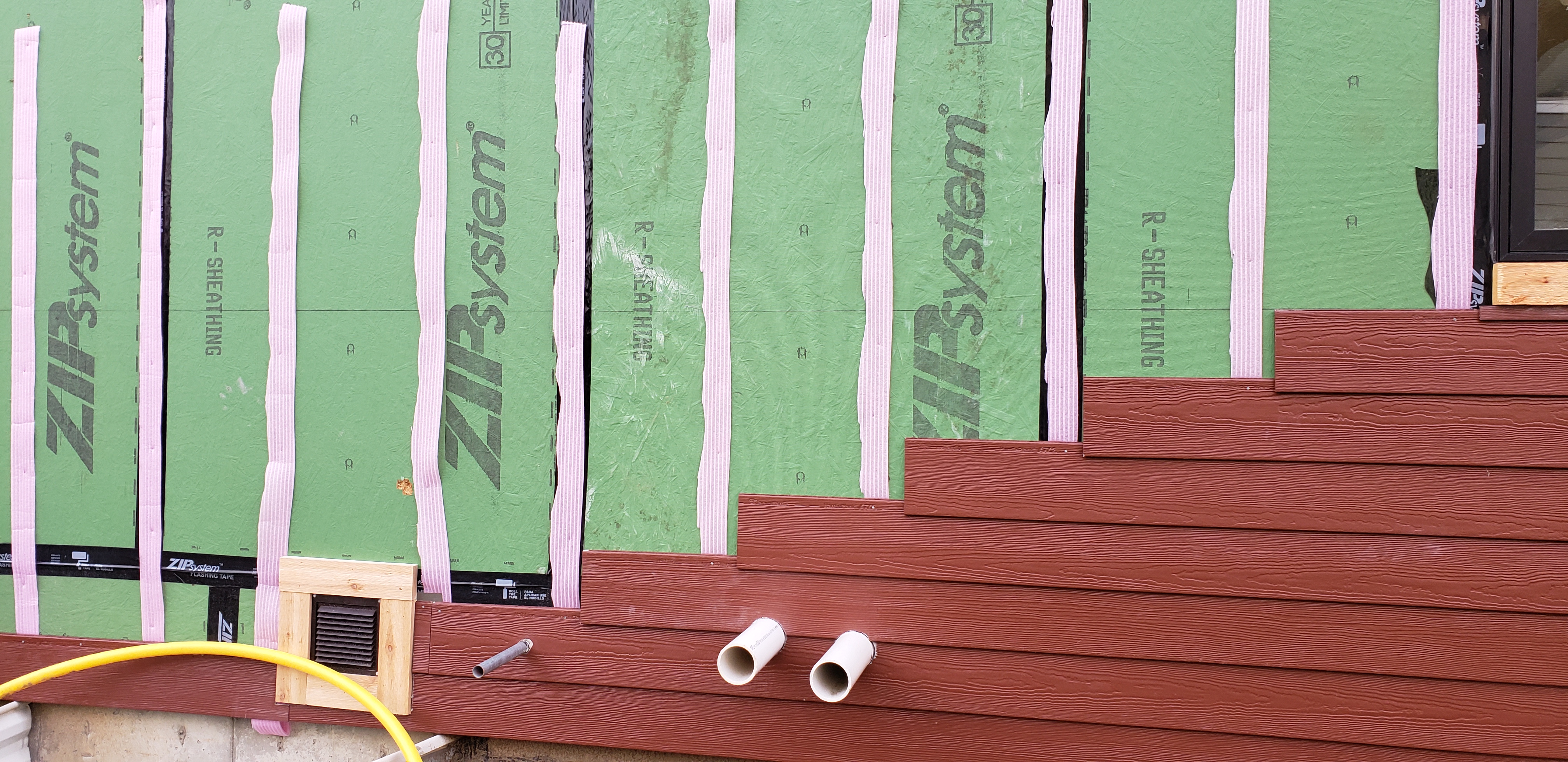
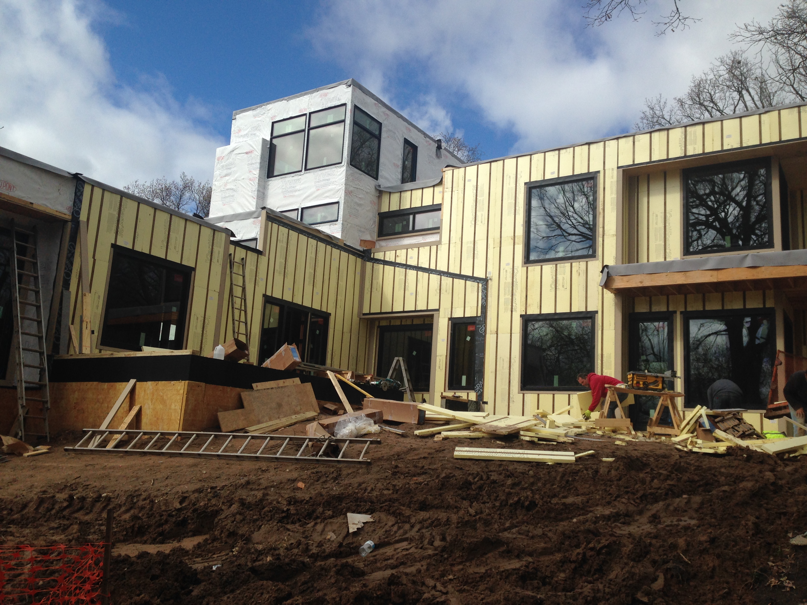
This guide describes the steps for replacing a home’s existing cladding with insulated vinyl siding (Figure 1).
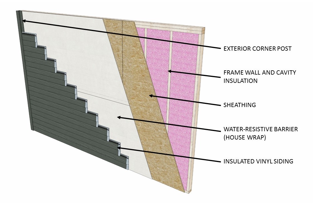
Insulated vinyl siding is a wall cladding that consists of vinyl siding with a permanently attached rigid foam backing, most commonly made of expanded polystyrene (EPS). The International Energy Conservation Code (IECC) recognizes it as a form of continuous insulation when the tested R-value (a measure of thermal resistance) is R-2 or greater. Insulated vinyl siding provides the following benefits:
- It improves the home’s energy performance by providing a continuous layer of thermal resistance to the home’s exterior walls. The insulated vinyl siding reduces the effect of thermal bridging that takes place through the wall’s framing members (wall studs have lower R-values than the cavity insulation), which keeps more heat in the home during the winter and out during the summer.
- It can reduce wall sheathing moisture content by keeping the wall cavity at a higher temperature as compared to other claddings, thereby reducing the likelihood of water vapor condensation.
- It improves a home’s airtightness as a result of the snug fit of the foam backing at installation. This effect is amplified when coupled with air-sealing around windows, doors, and penetrations through above-grade walls. [See Building America Case Study: Insulated Siding Retrofit in a Cold Climate.]
- It can improve the aesthetic appeal of a home as this is an upmarket cladding.
This retrofit measure can help a home owner to improve the energy performance and increase the curb appeal of their house. Insulated siding is further described in the Building America Solution Center guide Continuous Rigid Insulation Sheathing/Siding.
When replacing a home’s existing cladding with insulated vinyl siding, the retrofit professional – designer, rater, or contractor – must incorporate the new siding into the wall’s moisture control strategy. Doing so will maximize this retrofit measure’s effectiveness and avoid any adverse moisture issues.
Existing Moisture Problems
Insulated vinyl siding must never be installed over wall systems that show evidence of moisture problems until the underlying causes of the problem are addressed. Prior to installing the insulated vinyl siding, the retrofit professional must thoroughly inspect the condition of the exterior walls for evidence of moisture damage (e.g., staining, mold, rot). This includes an inspection of the existing cladding, the sheathing once the existing cladding is removed, and the interior wall finish. It is also important that the wall is inspected for the presence and type of interior vapor retarder.
During the inspection, the retrofit professional must also note whether the existing wall has a water-resistive barrier (house wrap), and, if present, its condition and integration with flashing. Many older homes do not have house wrap. Where house wrap is present, it will be necessary to cut the existing house wrap in a few key locations in order to inspect the exterior sheathing; if the house wrap will not be replaced, the cuts must be sealed using approved tape. Where other types of drainage plane are present, such as asphalt felt, the recommended strategy is to remove these materials and install a plastic house wrap to provide a smooth and uniform surface for the installation of the insulated vinyl siding.
The retrofit professional must identify the source of any moisture damage found and develop a strategy for correcting the issue. Only after steps are taken to remediate any existing damage can the retrofit continue and the insulated vinyl siding be installed.
As with any wall, the moisture control strategy for a retrofit must include the water-resistive barrier, flashing of wall penetrations, any exterior foam sheathing, vapor retarders, and air barriers.
Water-Resistive Barrier (WRB)
The function of a water-resistive barrier (WRB) is to shed to the outside any liquid water that has penetrated behind the cladding, thus stopping water from traveling further into the exterior wall system. The WRB is installed behind the cladding and is also known as a drainage plane. The most likely material to be used as the WRB for a re-cladding with insulated vinyl siding is a synthetic house wrap. When installation of a house wrap is required, either because the current one is damaged or because none exists (most likely in older homes), it must be installed horizontally with the upper layer lapped over the lower layer not less than 2 inches. See Building America Solution Center: Drainage Plane Behind Exterior Wall Cladding. Table 1 describes best practices.
Flashing
It is very probable that an older home will have missing or inadequately installed flashing, thus requiring a repair or replacement. Given that flashing must be integrated with the WRB in order for rain water to be properly shed, an ideal time to add flashing is when upgrading the cladding on an older home that has no WRB. The specific steps for flashing the windows and doors, and integrating the flashing with the WRB, will depend on (1) whether the windows and doors will be replaced or not, (2) the window/door type, (3) the window/door/WRB installation sequence, and (4) whether the home retrofit will also include the installation of exterior rigid foam sheathing. If the windows will be replaced and new house wrap will be installed, new home construction installation practices should be followed. These are described in the Building America Solution Center guide, Fully Flashed Window and Door Openings. If not replacing the windows, the new house wrap must be integrated with the window flashing. New (or repaired) flashing will be needed in many cases to ensure a continuous WRB. If the windows will be replaced and the existing water resistive barrier will remain in place, new flashing should be integrated with the existing WRB. Where the condition of the existing WRB does not allow for integration with new flashing, it is recommended that the WRB be replaced, at least in those wall sections where windows and doors are present. (If adding a new section of WRB, make sure to maintain shingle-style layering). If not replacing the windows, confirm that the existing WRB and flashing are adequate; repair if repairs are needed.
For a primer on window and door flashing, see the Home Innovation Research Labs’ TechNotes – Window and Door Flashing.
Exterior Foam Sheathing (Continuous Insulation)
If insulated vinyl siding is installed over exterior foam sheathing, the retrofit professional must establish the location of the WRB. It can be (1) house wrap installed between the structural sheathing and the exterior foam sheathing, (2) house wrap installed on the exterior face of the foam sheathing, or (3) the foam sheathing with taped joints, if approved for this application. Window and door flashing integration with the WRB will vary based on the WRB location.
The thickness of the insulated vinyl siding, installed over exterior foam sheathing, may require that the window and door trim be built out. If installing flanged windows with flanges at the foam sheathing surface, the manufacturer may require direct contact between the flange and the wood framing, i.e., extending or adding framing to the perimeter of the rough opening.
Vapor Retarders and Air Barriers
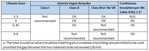
Even though its EPS-foam backing is semi-permeable, insulated vinyl siding is an unvented cladding so the wall sheathing has a limited ability to dry to the outside. It is recommended that insulated vinyl siding not be installed over a wall that has a Class I vapor retarder on the interior of the wall (i.e., polyethylene, vinyl wallpaper, or closed-cell spray polyurethane foam). Otherwise a double vapor barrier condition will be created where wall cavity drying is substantially impeded in both the interior and exterior directions. Such walls lack the ability to quickly recover from incidental moisture (e.g., window leaks, air leaks at penetrations, etc.). On the other hand, adding an insulative value of only R-2 to the exterior of the wall is not sufficient for controlling vapor drive in walls without an interior vapor retarder or with a Class III vapor retarder in Climate Zones 5 and higher.
Table 1 summarizes recommendations for whether insulated vinyl siding should be installed on a home based on whether the home has an interior vapor retarder, the home’s climate zone, and the use of added exterior continuous insulation. For more on vapor retarders, see the water vapor management chapters in the construction guides for high-performance 2x4 and 2x6 walls by Home Innovation Research Labs.
During the initial inspection, the retrofit professional should check for the presence of an interior vapor retarder in so far as that is possible. If it is discovered that the walls have an interior polyethylene vapor barrier, the retrofit professional must advise the home owner that installing insulated vinyl siding can create a double vapor barrier. If vinyl wallpaper is present on exterior walls, it should be removed before installing insulated vinyl siding. If the re-siding with insulated vinyl siding is being carried out in conjunction with installation or replacement of cavity insulation, the retrofit professional must advise the home owner that the use of closed-cell spray polyurethane foam (cc SPF) in the wall cavity will also lead to a double vapor barrier. Open-cell SPF is appropriate for cavity insulation as it is vapor-permeable.
Field testing has shown that installing insulated vinyl siding leads to improved air tightness due to the installation requirement that the foam backing of adjoining panels be in contact. [See Building America Case Study: Insulated Siding Retrofit in a Cold Climate.] The exterior air barrier can be the house wrap, the structural sheathing, or (if installed) the exterior foam sheathing. Any of these materials must be taped at the seams and joints to serve as an effective air barrier.
Materials and Installers
The materials and tools needed for the installation of insulated vinyl siding are listed in Table 2. Re-siding an existing home with insulated vinyl siding can be undertaken by a licensed siding contractor or by the home owner. The “installer” in the instructions below refers to either the contractor or the home owner.

How to Install Insulated Vinyl Siding
The following is a generic guide for installing insulated vinyl siding based on industry guides and recommendations. The installer must always conform to the siding manufacturer’s installation instructions.
1. Prepare the wall exterior. Remove the existing cladding. Inspect for and repair any moisture damage.
2. Inspect to ensure the substrate is smooth. Pound or remove protruding nails. Scrape off and replace any loose caulk.
3. Install the water resistive barrier (house wrap) and integrate it with flashing around the windows and doors. If required by the project specifications, install rigid foam sheathing before vinyl siding.
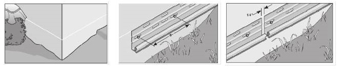
4. Install the starter strip. Before installing the starter strip:
- Measure up from the top of the foundation 3 inches (or ¼ inch less than the width of the starter strip) and partially drive in a nail to mark the spot.
- Attach a chalk line to the nail, go to the next corner and pull the line taut.
- Make sure the line is level by using a line level or a 4-foot level.
- Snap the chalk line. Repeat around the entire house. Ensure that at least 8 inches of foundation wall will be visible below the siding all the way around.
- Alternatively, you can measure down from the soffit at one corner of the house to the top of the foundation and subtract ¼ inch less than the width of the starter strip then mark a spot. Then go to the next corner and measure down the same distance and make a mark. Then, snap a chalk between the two marks.
To install the starter strip:
- Align the top of the starter strip with the chalk line (Figure 2).
- Fasten the starter strip every 8 to 12 inches with fasteners placed at the center of the nail slots.
- Leave ¼ inch between each section of starter strip to allow for expansion and contraction.
- Don’t pound the nails flush. Leave a 1/32-inch clearance between the nail heads and the starter strip.
5. Install the corner posts. Install the siding accessories before installing the siding panels. These accessories include the proper inside and outside corner posts for the home’s geometry as well as the j-channel around the windows and doors.
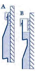
The outside corner posts must be the ones specified to go with the insulated vinyl siding. If the product does not include outside corner posts, then use a normal corner post (one without the insulation offset), but shim it to accommodate the added thickness of the insulated vinyl siding due to its foam backing. Install each corner post, starting from the eave and working down (Figure 3):
- Leave a ¼-inch space between the top corner post and the bottom of the eave.
- The top fastener (nail or staple) goes in at the top of the upper slot on both sides of the post.
- Space out subsequent fasteners every 8 to 12 inches and place at the center of the slot.
- Do not drive nail heads tightly against the corner post, but instead leave 1/32-inch clearance to allow for expansion and contraction to occur.
- If more than one piece of corner post is installed, fit it under the upper post. To do this, cut out 1 inch from the nail hem from the bottom end of the top corner post piece, and slide the lower corner post under the corner post piece above it to overlap by ¾ inch (Figure 3).
- Terminate the corner post ¾ inch under the bottom of the starter strip.

6. Install the J channels. Install the j channel around the windows and doors after the windows and doors have been installed and properly flashed:
- Cut the drip cap at the top of the window or door to the proper length: the width of the window or door plus twice the width of the j-channel’s face.
- Make a 1-inch notch at each end of the drip cap, to later be bent down and over the side trim j-channels thus provide flashing of the window trim.
- Cut the side j-channels to measure the height of the window plus the width of the j-channel face.
- Make a 1-inch notch at the bottom end of each side trim j-channel.
- Cut the j-channel for the bottom of the window to measure the width of the window plus twice the width of the j-channel’s face.
- Cut out a 1-inch tab from both ends of the window bottom j-channel.
- Install all j-channel flush against the window/door with fasteners every 8 to 12 inches (the top fastener for the side-trim j-channel should go in at the top of the upper slot).
- Bend the two end notches of the drip cap down and over the side trim j-channel.
- Bend the bottom notch of each window side trim j-channel in and over the bottom j-channel.
- Install the side trim j-channel on both sides of the window or door shall be installed flush with the bottom of the drip cap j-channel.
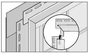
Install the j-channel around the windows and doors after the windows and doors have been installed and properly flashed:
- Cut the drip cap at the top of the window or door to the width of the window or door plus twice the width of the j-channel’s face.
- Cut each end of the drip cap to make a 1-inch tab at each end of the drip cap, to later be bent down and over the side trim j-channels (Figure 4).
- Cut the side j-channels to measure the height of the window plus the width of the j-channel face.
- Cut the bottom ends of the side trim to form a 1-inch tab at the bottom end of each side trim j-channel.
- Cut the j-channel for the bottom of the window to measure the width of the window (Figure 5).
- Cut out a 1-inch notch from both ends of the window bottom j-channel, if recommended by manufacturer.
- Install all j-channel flush against the windows or doors with fasteners every 8 to 12 inches (the top fastener for the side-trim j-channel should go in at the top of the upper slot).
- Install the side trim j-channel on both sides of the window or door so it is flush with the bottom of the drip cap j-channel.
- Bend the two end tabs of the drip cap down and over the side trim j-channel.
- Bend the bottom tabs of each window side trim j-channel in and under the bottom j-channel.

7. Install the first course. Install the first (bottom) course of insulated vinyl siding panels along a wall:
- Engage the bottom of the insulated vinyl siding panel with the bottom of the starter strip and slide the panel into the pocket of the corner post (Figure 6).
- If the installation is taking place when the outdoor air temperature is > 40°F, leave a ¼-inch gap between the end of the insulated vinyl siding panel and the trim to allow for movement. If the outdoor air temperature at the time of installation is < 40°F, leave a 3/8-inch gap.
- Fasten the first panel in the center of the nail hem slot, leaving a 1/32-inch clearance between the nail heads and the nail hem to allow for expansion and contraction. Do not fasten more than 16 inches apart.
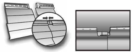
- Slip the face of the next panel of insulated vinyl siding above or below the face of the first panel (depending on how the home owner wants the seams to appear). Position the face of the panel that is below between the other panel’s face and the foam backing.
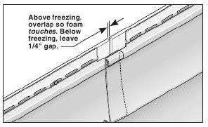
- Slide the panels together until the foam backing of both panels are in contact (no gap) for installations > 40°F, or with a gap of ¼ inch for installations < 40°F, or as specified by the manufacturer (Figures 7 and 8).
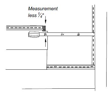
- When measuring the length of the final panel to the corner post, measure from the inside of the wall post to the foam backing of the previous panel (not the panel face) to ensure proper fit of the final panel and allow ¼ inch for expansion (Figure 9).
- To cut a panel to a desired length, use a circular saw with a fine-toothed plywood blade turned backwards, and cut slowly with the vinyl side face up, cutting completely through the foam.
- For subsequent courses, stagger the lengths of siding panel so that the seams (laps) of one course do not align vertically with the seams (laps) of the next course.

8. Cut and seal around fixtures and protrusions.
When encountering exterior lighting or water spigots, follow common cutting procedures that are used for non-insulated vinyl siding panels to accommodate these protrusions. Install premade gaskets or flashing around these protrusions that are properly integrated with the water resistant barrier, before installing the siding.
9. Cut and fit panels around windows.
When encountering windows on an exterior wall, it is likely that the insulated vinyl siding panel will need to be cut to accommodate the dimensions of the window.
- If the piece below the window needs to be cut, hold the panel under the window and mark the width and depth of the window on the panel (Figure 10). Add ¼ inch to all three sides to be cut to allow for expansion and contraction.
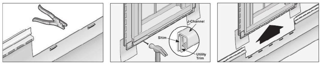
- Cut the panel with a utility knife and tin snips.
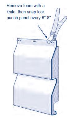
- Remove approximately 1 inch of the foam backing from the cut edge of the panel.
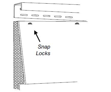
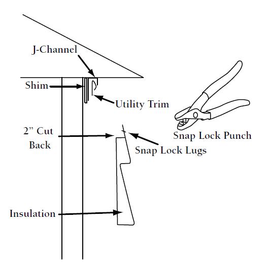
- Use a snap lock punch to crimp the cut edge of the panel every 6 inches so the raised lug is on the outside face (Figure 11).
- Install utility trim inside the window bottom j-channel to receive the cut edge of the panel. Install furring if needed to maintain the face of the panel at the desired angle.
- Use a nail slot punch to create additional nail slots at the cut edge of the panel.
- Install the panel, ensuring that the bottom edge of the panel locks in with the top edge of the panel below it, and pulling up until the crimped/cut edge of the panel slips under and engages the undersill/utility trim installed in the window bottom j-channel (Figure 12).
- Fasten through the newly created nail slots on the cut edge of the panel.
10. Install final course and soffit.
The final course of insulated vinyl siding will meet up with the soffit panels. If the width of the final course does not need to be cut due to the wall height, then simply install by engaging the bottom of the final panel with the top of the panel below and sliding the top under the j-channel. Secure it with fasteners not more than every 16 inches like the other panels.
If the final panel must be cut to fit:
- Use shimmed utility trim installed inside the j-channel to secure the top edge of the insulated vinyl siding panel.
- Remove 1 inch of foam backing from the top edge. Crimp out-facing lugs every 6 inches along the cut edge using a snap lock punch (Figure 13). Create nail slots at the edge using a nail slot punch. Fasten the panel into the utility trim using fasteners spaced not more than every 16 inches.
- The installation of the soffit does not change.
Special Installation Considerations
Fasteners: The code-minimum fastener for insulated vinyl siding fasteners is a 0.120 shank nail with a 0.313 head or 16-gage crown that is long enough to penetrate the sheathing or other nailable substrate and framing a total of at least 1¼ inches. If foam sheathing is used, it is not considered a nailable substrate, and so the nail would have to be long enough to accommodate the thickness of the foam and still penetrate 1¼ inches. The insulated vinyl siding manufacturer must specify if their product can be used with exterior foam sheathing, and which fasteners can be used for various applications. IRC Table R703.15.1 and Table R703.15.2 contain the requirements for fastening cladding directly to foam sheathing or using furring, respectively.
Furring strips: In order for insulated vinyl siding to be considered continuous insulation, it must be installed directly over a water-resistive barrier and sheathing. Therefore, if the installer is using furring strips for an even installation, the area between the furring strips must be filled in with rigid insulation or another approved material. Note, however, that some manufacturers do not allow the installation of their product over furring strips.
Field-cut lapping: It is always recommended that the installer lap only factory cut ends, but it is understood that lapping a field cut end may be necessary. When this is the case, remove ¾ inch of foam backing from the field cut end. The factory-cut panel should be the overlapping panel.
Ensuring Success
Assess and correct moisture problems in walls, windows, and doors before installing the vinyl siding.
To ensure the durability of the wall system, avoid setting up a double vapor barrier condition, which impedes wall drying to the interior and exterior. Insulated vinyl siding should not be installed on a house with an interior polyethylene vapor retarder or vinyl wallpaper. If either exists, they should be removed before installing the vinyl siding. If the re-siding is being undertaken in conjunction with the installation of new cavity insulation, closed-cell spray polyurethane foam is also not recommended to avoid the double vapor barrier.
Region
The exterior wall assembly should be designed for a specific hygrothermal region, rain exposure zone, and interior climate.
The map in Figure 1 shows the climate zones for states that have adopted energy codes equivalent to the International Energy Conservation Code (IECC) 2009, 12, 15, and 18. The map in Figure 2 shows the climate zones for states that have adopted energy codes equivalent to the IECC 2021. Climate zone-specific requirements specified in the IECC are shown in the Compliance Tab of this guide.
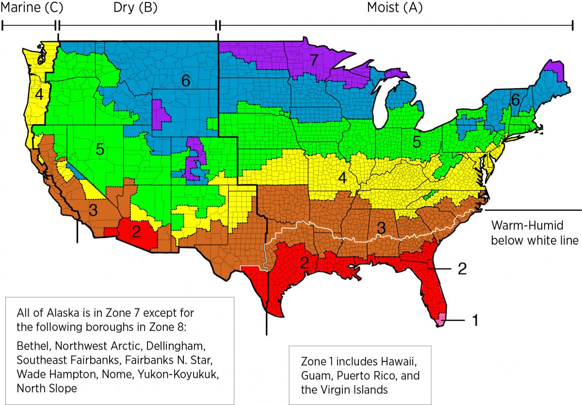
Figure 1. Climate Zone Map from IECC 2009, 12, 15, and 18. (Source: 2012 IECC)

Figure 2. Climate Zone Map from IECC 2021. (Source: 2021 IECC)
Table 1 below provides the minimum R-values and equivalent U-factors for frame walls as specified in the 2009, 2012, and 2015 International Energy Conservation Codes:

Table 1. Minimum R and U Values for Frame Walls from 2009, 2012, and 2015 IECC. (Source: 2012 IECC)
To meet the R-5 continuous insulation requirement, the insulated vinyl siding (generally rated between R-2.0 to R-2.8) can be combined with the rigid foam insulative sheathing types shown in Table 2.
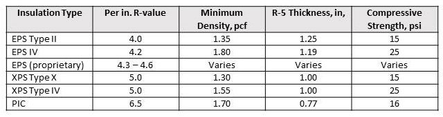
Table 2. Rigid Foam Sheathing Types that can Be Combined with Insulated Vinyl Siding to meet R-5 Continuous Insulation Requirement.
When choosing to use these rigid foam sheathings, the retrofit professional must be sure that the insulated vinyl siding fasteners will be able to withstand the dead load from the weight of the insulated vinyl siding for the given thickness of the rigid foam sheathing, while still complying with the manufacturer’s type and diameter specifications. Minimum fastening requirements for cladding installed directly over foam plastic sheathing are contained in IRC Table R703.15.1 (and Table R703.15.2 for furred cladding attachment).
Training
Right and Wrong Images
Source
Source
Source
Source
Presentations
Compliance
More Info
Case Studies
References and Resources
*For non-dated media, such as websites, the date listed is the date accessed.
Contributors to this Guide
The following authors and organizations contributed to the content in this Guide.
Sales
High-R Wall Insulation = High-Efficiency or Ultra-Efficient Wall Insulation
Technical Description
There are two levels of wall insulation: high-efficiency insulation, which meets the 2015 International Energy Conservation Code, and ultra-efficient insulation, which is 25% more efficient than this national code. Using high-efficiency and ultra-efficient insulation along with professional installation (e.g., no gaps, voids, compression, or misalignment with air barriers, complete air barriers, and minimal thermal bridging) creates conditioned spaces that require very little heating and cooling, along with even comfort and quiet throughout the house.
Questions? Comments? Contact our webmaster.