Scope
Install and commission ducted and ductless heat pumps using smart tools to improve system performance, reduce energy waste, and reduce customer callbacks:
- Perform the following tests using smart digital tools on all heat pump systems:
- Nitrogen Pressure Test
- Vacuum Decay Test
- Refrigerant Charge Verification
- Controls Verification
- For ducted heat pump systems, perform the following additional tests:
- Total External Static Pressure (TESP)
- Airflow Measurement
- Duct Leakage Test
- System Performance Verification (Capacity and Efficiency)
See the Compliance tab for links to related codes and standards and voluntary federal energy-efficiency program requirements.
Description
Importance of Proper HVAC Commissioning
Research shows that most residential HVAC systems aren’t installed correctly, and that can cause a lot of problems for both homeowners and contractors. The prevalence of improper installation is a significant concern, as evidenced by various research findings. For instance, research indicates that 70-90% of air conditioner and heat pump systems exhibit at least one performance-compromising fault due to improper installation or inadequate maintenance (DOE 2018). When factoring in duct leakage, these rates escalate to an alarming 90-100%. Proper commissioning of systems can reduce faults introduced during installation and can result in significant performance improvements.
Impact of Improper Installation
The impacts of improper HVAC installation extend broadly, affecting both energy efficiency and occupant utility costs. According to a model developed by the National Renewable Energy Laboratory (NREL), improper HVAC installation is not only an energy efficiency concern but also has substantial financial implications. The NREL model estimates that approximately 9% of the energy used in HVAC systems nationwide is attributed to installation-related faults. Nationally, this energy waste results in an increase of approximately $2.5 billion in utility bills annually (NREL 2020).
Research on sensitivity analysis of installation faults revealed that airflow and refrigerant charge faults significantly increase energy consumption in heat pumps. Even modest deviations from manufacturer recommendations—like airflow reductions of 15% or refrigerant undercharges of 20%—can lead to noticeable energy inefficiencies (NIST 2014). Contractors should prioritize proper installation to avoid these costly energy losses.
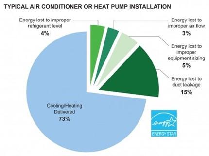
Common installation faults such as improper refrigerant charge, airflow, and duct leakage can lead to a reduction of delivered cooling or heating as illustrated in Figure 1. The chart depicts that 4% of energy losses are due to improper refrigerant levels, 3% due to improper airflow, and 15% attributed to duct leakage.
Premature equipment failure is also a risk, as strain from improper installation can cause components to fail early, necessitating expensive repairs or replacements. Comfort issues such as uneven heating or cooling may arise from poor installation. Noise complaints are another potential consequence, as faulty installation can lead to noisy operation.
What is Commissioning?
Commissioning is the process of ensuring that the heating or cooling system is designed, installed, tested, and operating as intended. Unfortunately, standard industry practice rarely includes commissioning and often no performance testing is completed after equipment start-up. Commissioning involves testing to confirm that the system's performance, including capacity and efficiency, aligns with the design specifications. It is essential to have a qualified HVAC technician perform thorough commissioning.
The lack of broad industry adoption of commissioning is mainly attributed to a lack of awareness or training. There is also a perception that commissioning is time-consuming and not cost-effective for the contractor. However, modern technology is making commissioning less time-consuming and easier.
Commissioning with smart tools provides more value to contractors through callback reduction. Smart diagnostic and commissioning tools streamline data collection, provide commissioning workflows, and generate detailed reports that help technicians communicate more effectively with homeowners. These advancements make the process faster, easier, and more accessible for HVAC contractors.
Heat Pump Quality Installation and Commissioning: Key Tests and Procedures
According to the Air Conditioning Contractors of America (ACCA) Quality Installation Specification and Verification Protocols (ACCA 2016), four core areas characterize a quality installation:
- Design (e.g., load calculations, equipment selection, system matching, and ventilation)
- Equipment Installation (e.g., static pressure, refrigerant charge, power, and controls)
- Distribution (e.g., duct leakage and balancing)
- System Documentation and Owner Education.
This guide focuses on the equipment installation, distribution, and system documentation aspects of quality installation for both ducted air-source heat pumps and ductless heat pump systems. For guidance on system design and sizing, refer to the Mechanical Air Conditioning guide and the Cold Climate Heat Pump Sizing and Selection guide. Specific information on split heat pumps can be found in the Traditional Split Heat Pumps guide while details on ductless heat pumps are provided in the Ductless (Mini-Split) Heat Pumps guide.
The quality installation and commissioning of residential heat pumps rely heavily on several key tests and procedures. Advancements in test instruments (such as smart diagnostic tools) have streamlined the application of these tests and procedures, enabling standardization of testing and reporting across the industry.
Tests that should be performed for both ducted and ductless systems include:
- Nitrogen Pressure Test
- Vacuum Decay Test
- Refrigerant Charge Verification
- Controls Verification
Additional tests are necessary where ductwork is installed:
- Total External Static Pressure (TESP)
- Airflow Measurement
- Duct Leakage Test
- System Performance Verification (Capacity and Efficiency)
To ensure success, these tests and procedures should be used in concert with visual inspection throughout the installation and commissioning processes and should be completed by a trained and qualified technician.
Test Procedures Performed during Commissioning
A properly installed and commissioned system starts during design and equipment selection. It is important to follow best practices when sizing and selecting a heat pump system. The following test procedures that are performed during equipment installation or after startup are critical to ensuring proper system performance. Some manufacturers require a subset of these tests to qualify for extended equipment warranties. In addition, the tests performed will vary depending on if the equipment has, or does not have, ductwork for air distribution.
Tests for Both Ducted and Ductless Systems
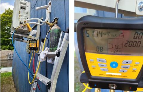
- Nitrogen Pressure Test – This pass/fail test checks the integrity of the refrigerant lines and connections and involves pressurizing the refrigerant lines with dry nitrogen gas to verify that the system is sealed under pressure. See Figure 2. While the system is under pressure, a bubble test is performed to check for and pinpoint leak locations - paying close attention to field-made joints and connections. A nitrogen pressure test usually consists of the following steps:
- The system is first purged with nitrogen to remove any remaining air or other gases.
- The system is then gradually pressurized with nitrogen. For a residential system, typically the system will be pressurized somewhere between 250-600 PSIG, however, it is important to follow the manufacturer's recommendations.
- Once the system reaches the recommended test pressure, the refrigerant piping should be valved off from the nitrogen tank and typically held for 30-60 minutes.
- If the pressure drops during the test, it indicates the system is leaking. The location of the leak should be identified and corrected. A suitable leak detection method includes:
- Visual inspection: Look for obvious signs of leaks at joints and connections.
- Bubble test: Spray a soapy solution on joints and connections. If bubbles form, it indicates a leak at that location.
- Listening: In a quiet environment, listen for the hissing sound of escaping gas, which can indicate a leak.
- Ultrasonic testing: Use ultrasonic devices to detect the sound of escaping gas, which is often beyond the range of human hearing.
- Electronic leak detectors: Employ electronic detectors for precise leak localization.
- Using digital gauges and/or smart diagnostic applications for this test improves accuracy by compensating for temperature changes and resulting nitrogen pressure changes.
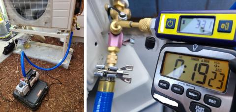
- Vacuum Decay Test – This pass/fail test involves evacuating the refrigerant lines using a vacuum pump and is completed following the nitrogen pressure test. This process helps remove moisture and gases and serves as an additional check for leaks in the refrigerant piping. To pull a deep vacuum quickly, it is important to have an efficient set-up. This includes one, or several, large diameter vacuum-rated hoses, a vacuum pump with clean oil, valve core removal tools, and a digital micron gauge. This test involves pulling a vacuum below 500 microns. Once the target vacuum level is reached, the vacuum pump and hose should be valved off. During the subsequent decay test, the system’s pressure is monitored for at least 10 minutes. The system passes if the vacuum level does not change much (typically by less than 50 microns) and is held under 500 microns for the duration of the test. This is an indication that the system is dry and leak-free. Digital or smart tools, such as digital micron gauges, are particularly helpful as they provide accurate, real-time readings, detect minor pressure changes, and improve the testing process's overall efficiency and reliability. See Figure 3.
- Refrigerant Charge Verification – Proper refrigerant charge is essential for efficient HVAC system operation. Three methods — superheat, subcooling, and weigh-in — are commonly employed to verify the refrigerant charge and are tailored to different system configurations and components (such as the type of refrigerant metering device). In routine service and maintenance, technicians commonly rely on the superheat and subcooling methods to verify refrigerant charge, while the weigh-in method is typically employed during initial installation, major repairs, or retrofitting of systems. Common methods for verifying refrigerant charge are described below:
- Superheat Method: This method is typically applied to equipment with fixed orifice metering devices. Superheat refers to the temperature of the refrigerant vapor above its boiling point in the evaporator. By measuring the temperature of the refrigerant vapor leaving the evaporator (suction line) and comparing it to the saturation temperature corresponding to the evaporator pressure, technicians can determine the superheat. The appropriate superheat value varies depending on factors such as system design and operating conditions. Deviations from the expected superheat can indicate refrigerant undercharge or overcharge.
- Subcooling Method: The subcooling method is used for systems equipped with thermostatic expansion valves (TXVs). Subcooling refers to the temperature difference between the liquid refrigerant and its saturation temperature at a given pressure. The temperature of the liquid refrigerant leaving the condenser (liquid line) is measured and compared to the saturation temperature corresponding to the condenser pressure. The difference between these temperatures is the refrigerant subcooling. Similar to superheat, the appropriate subcooling value depends on system design and operating conditions. Deviations from the expected subcooling can indicate refrigerant undercharge or overcharge.
- Weigh-in Method: Manufacturers often pre-charge equipment with the appropriate refrigerant amount and furnish guidelines or tables for refrigerant to be added if the line-set length is beyond the length the factory charge can handle. The weigh-in method involves adding refrigerant until the correct weight is achieved. A refrigerant scale is used to precisely measure the amount of refrigerant added to the system. This method is particularly useful during initial installation.
- Controls Verification – Thorough testing of the system's control components ensures the air conditioner or heat pump operates as intended and responds correctly to user settings. This includes verifying the thermostat's communication with the system, its accurate temperature sensing, and its ability to maintain desired comfort levels. For systems with multiple heat sources (e.g., heat pump with gas backup heat, or heat pump with electric backup heat), it is important to ensure that the backup heat source will only operate below the balance point temperature. Additionally, it's important to test airflow components like fans, blowers, and dampers (if present) to maintain correct airflow throughout the system.
Tests for Ducted Systems Only
- Total External Static Pressure (TESP) – Measuring TESP helps evaluate ductwork performance, identify restrictions, and ensure operation within equipment specifications. High TESP can lead to reduced airflow, decreased system efficiency, and comfort issues. A process for measuring TESP includes:
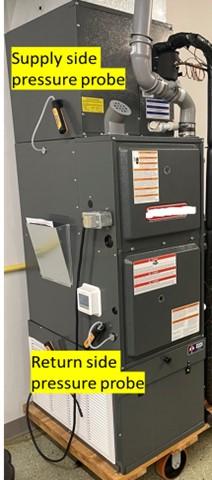
- Identifying Measurement Locations: Static pressure measurement locations are identified. Depending on the system configuration, this is typically located just after the filter on the return side and just after the fan in a fan-coil configuration, or between the heat exchanger and the indoor coil in a furnace configuration on the supply side. See Figure 4.
- Drilling Pressure Taps: Holes just large enough to fit static pressure probes are drilled in the identified locations, being careful not to drill into any important system components. These pressure taps should be sealed with rubber plugs to prevent air leaks after completing the measurements.
- Measuring Return Static Pressure: After being zeroed, a static pressure probe is inserted into the first pressure tap on the return side, ensuring the probe tip is pointing into the direction of airflow. The return static pressure is recorded.
- Measuring Supply Static Pressure: After being zeroed, a static pressure probe is inserted into the second pressure tap on the supply side, ensuring the probe tip is pointing into the direction of airflow. The supply static pressure is recorded.
- Calculating TESP: TESP is calculated by summing the absolute value of the return static pressure and the supply static pressure.
- Comparing with Manufacturer’s Specifications: The measured TESP is compared with the acceptable range specified by the manufacturer. If out of range, corrections are made to the system to bring TESP within range.
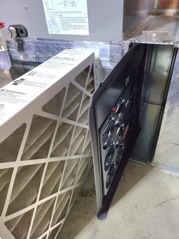
- Airflow Measurement – Measuring airflow across the indoor coil, outdoor coil, and throughout supply registers is crucial. It ensures the system delivers the designed volume of air for proper heating/cooling. By comparing measured airflow to manufacturer specifications or design requirements, technicians can identify issues impacting comfort and efficiency. There are several options for estimating or measuring airflow in residential HVAC systems. Some common methods include estimation using TESP and fan curves or direct measurement using a flow hood, flow grid (Figure 5), or the pressure matching method. The TESP method measures static pressure difference across the air handler or furnace and uses manufacturer fan curves to estimate airflow. The flow grid method involves insertion of a flow grid into the filter rack along with taking static pressure measurements to directly measure airflow, see Figure 5. The flow hood method involves direct measurement of airflow at supply and return grills. Finally, the pressure matching method involves measuring normal system operating pressure, then connecting a duct blower to the return. The system fan is turned on to pull all the air through the duct blower, and then the duct blower fan is turned on until the normal system operating pressure is reached – the calibrated duct blower will provide a CFM measurement at this pressure.
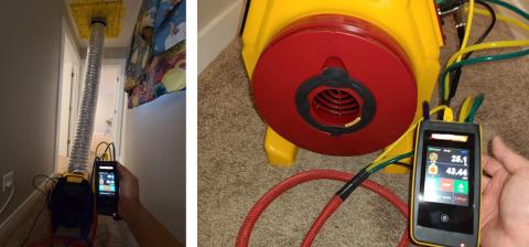
- Duct Leakage Test – This test quantifies leaks in the ductwork, helping verify compliance with building codes and energy efficiency standards. Excessive leakage can significantly decrease system performance, raise energy bills, and create comfort issues. Detailed information on conducting a duct leakage test can be found in the Total Duct Leakage Tests guide. See Figure 6.
- System Performance Verification – This test involves various checks to ensure the overall system operates as designed and meets performance expectations. Key elements include capacity and efficiency verifications for residential HVAC systems using smart tools to ensure optimal performance and energy efficiency. These tools enable convenient measurements of temperature, humidity, airflow, and power consumption, while also automatically calculating the cooling or heating capacity based on these readings and determining the system's Energy Efficiency Ratio (EER) or Coefficient of Performance (COP).
Overview of Commissioning and Diagnostic Tools
A number of commissioning and diagnostic tools are available to help HVAC technicians commission heat pumps. These tools can provide many benefits, including ease of data collection, standardized workflows for commissioning, and streamlined documentation and reporting functions.
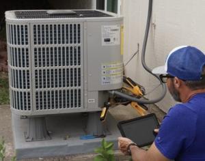
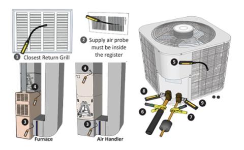
Smart diagnostic apps are designed to facilitate HVAC system performance analysis using data from a technician’s digital tools. Digital probes and sensors connect wirelessly to mobile apps to provide real-time analysis, automated calculations, and guided troubleshooting, significantly streamlining the commissioning process. A commissioning and diagnostic probe set might include psychrometer probes, static pressure probes, refrigerant pressure probes, pipe clamp thermometers, and a wireless clamp multimeter. A sample probe deployment for commissioning a new installation is shown in Figure 7 below.
The key features of smart diagnostic and commissioning tools include calculating HVAC system performance and efficiency, detecting faults, suggesting corrective actions, and providing workflows for consistent practices and third-party verification. For more information on smart diagnostic and commissioning tools, visit the DOE Smart Tools for Efficient HVAC Performance (STEP) Campaign.
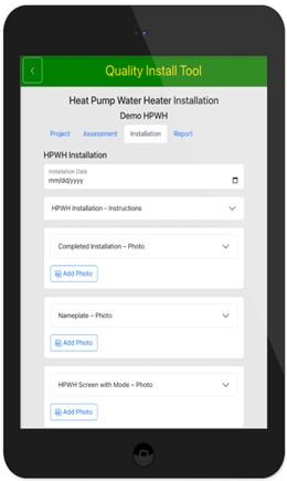
In addition to smart diagnostic tools, Pacific Northwest National Laboratory (PNNL) has developed the Quality Install Tool (Figure 8). The Quality Install Tool simplifies and standardizes installation documentation through photo-based prompts and automatically generates professional reports. This open-source web app is designed for versatility, encompassing a wide range of upgrades and installations.
Success
A quality-installed heat pump delivers optimized efficiency and comfort, but achieving these results goes beyond initial installation. Commissioning is the final step to ensure the system operates at its full potential. To guarantee success, follow:
● Quality Installation Standards: Adhere to industry quality installation standards such as ACCA QI-5, ACCA QI-9, ASHRAE standard 221, ANSI/RESNET/ACCA 310, and/or the ENERGY STAR for Homes National HVAC Commissioning Checklist.
● Manufacturer Instructions: While standards provide a framework, the heat pump manufacturer's specific commissioning procedures, specifications, and recommendations always take precedence.
● Verify Proper Refrigerant Charge: Refrigerant charging practices are fundamental for efficiency, system longevity, and correct superheat/subcooling values. Employ manufacturer-mandated procedures, utilize quality gauges and tools, and address any leaks.
● Verify Proper Airflow: Verify target airflow through the system is achieved. Perform duct leakage tests if poor airflow is suspected and follow best practices to minimize leakage.
● Leverage Technology: Efficiently collect data, analyze results, and generate accurate reports utilizing mobile commissioning apps and smart tools. These resources streamline work, increase professionalism, and reduce callbacks. They also help maintain detailed commissioning records.
By following these commissioning recommendations, homeowners will experience the complete benefits of their investment — lower energy bills, improved comfort, and a reliable system. It also demonstrates a commitment to quality, strengthening the reputation of technicians and contractors within the HVAC industry.
Compliance
More
More Info.
Access to some references may require purchase from the publisher. While we continually update our database, links may have changed since posting. Please contact our webmaster if you find broken links.
